GPS (Neo 6M) with STM32
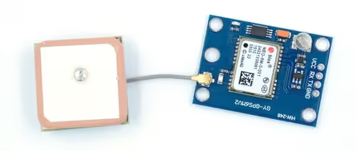
This tutorial will cover the Interfacing of the GPS Module (Neo 6M) with the STM32. We will see how we can get the location, time, date, speed, altitude etc.
As we are going to use the UART for the data transmission, also the length of the data is unknown, This tutorial is going to use the UART Ring Buffer from one of my previous Posts. It is recommended that you first go through that tutorial, and make it work.
The GPS module Transmits the data via the UART in the NMEA format. In this tutorial, we will see how to decode it and extract the useful information from this data. The sample data in the NMEA format is shown below.
$GPGGA,092750.000,5321.6802,N,00630.3372,W,1,8,1.03,61.7,M,55.2,M,,*76
$GPGSA,A,3,10,07,05,02,29,04,08,13,,,,,1.72,1.03,1.38*0A
$GPGSV,3,1,11,10,63,137,17,07,61,098,15,05,59,290,20,08,54,157,30*70
$GPGSV,3,2,11,02,39,223,19,13,28,070,17,26,23,252,,04,14,186,14*79
$GPGSV,3,3,11,29,09,301,24,16,09,020,,36,,,*76
$GPRMC,092750.000,A,5321.6802,N,00630.3372,W,0.02,31.66,280511,,,A*43
$GPGGA,092751.000,5321.6802,N,00630.3371,W,1,8,1.03,61.7,M,55.3,M,,*75
$GPGSA,A,3,10,07,05,02,29,04,08,13,,,,,1.72,1.03,1.38*0A
$GPGSV,3,1,11,10,63,137,17,07,61,098,15,05,59,290,20,08,54,157,30*70
$GPGSV,3,2,11,02,39,223,16,13,28,070,17,26,23,252,,04,14,186,15*77
$GPGSV,3,3,11,29,09,301,24,16,09,020,,36,,,*76
$GPRMC,092751.000,A,5321.6802,N,00630.3371,W,0.06,31.66,280511,,,A*45VIDEO TUTORIAL
You can check the video to see the complete explanation and working of this project.
CubeMX Setup
I am using STM32F103C8T6 (BluePill) for this tutorial.
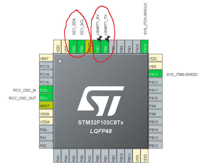
- As shown above, I have enabled the UART1 for communicating with the GPS Module
- Also the I2C1 is enabled , so that we can connect the LCD and display the results on it.
The Settings for the UART and I2C are shown below.
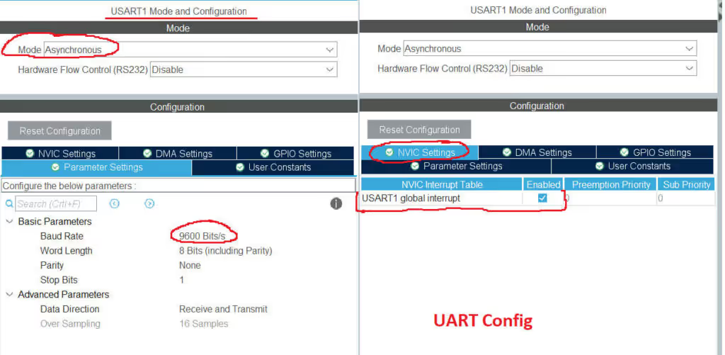
- As shown above, the UART Baud Rate is configured at 9600 bps. This is according to the Neo 6M
- We also need to enable the UART interrupt for the ring buffer to work.
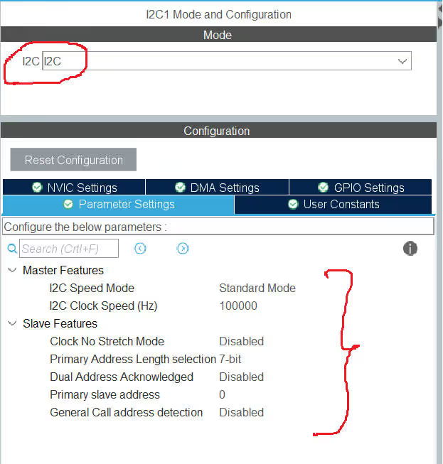
- Everything is set to default in the I2C Configuration.
Connection
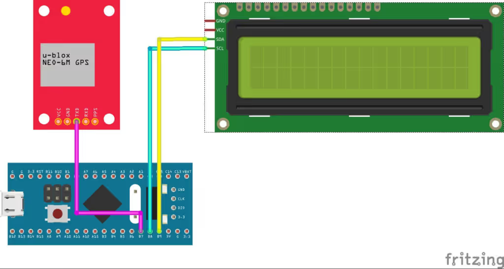
- As shown above, The Tx Pin of the Module (Neo 6M) is connected with the PB7 (Rx Pin) of the Controller.
- We only need to receive data, and hence one pin is enough.
- The PB8 and PB9 of the controller are connected to the SCL and SDA Pins of the LCD1602.
- The Module and the LCD must be powered with the external 5V supply, as the Bluepill’s 5V won’t be enough for both of them.
Some Insight into the CODE
As I have mentioned before, we need to use the UART Ring Buffer Library inorder to receive the data of unknown length. That is why the Ring Buffer Library will be included in the code.
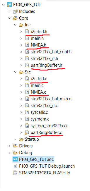
Along with the Ring buffer, I have also written a Library to decode the NMEA Data and we need to include it in our project. The project structure is as shown below.
Let’s Take a look at the NMEA.c File
First we are going to look at the Function to decode the GGA
/* Decodes the GGA Data
   @GGAbuffer is the buffer which stores the GGA Data
   @GGASTRUCT is the pointer to the GGA Structure (in the GPS Structure)
   @Returns 0 on success
   @ returns 1, 2 depending on where the return statement is excuted, check function for more details
*/

int decodeGGA (char *GGAbuffer, GGASTRUCT *gga)- The
decodeGGAfunction can be used to decode the GGA String. 
- The first parameter is the GGA Buffer, where the GGA string is saved, and the second parameter is the pointer to the GGA Structure, which is defined in the NMEA.h file.
Let’s see how the decoding actually works
Checking the Fix
	inx = 0;
	char buffer[12];
	int i = 0;
	while (GGAbuffer[inx] != ',') inx++;  // 1st ','
	inx++;
	while (GGAbuffer[inx] != ',') inx++;  // After time ','
	inx++;
	while (GGAbuffer[inx] != ',') inx++;  // after latitude ','
	inx++;
	while (GGAbuffer[inx] != ',') inx++;  // after NS ','
	inx++;
	while (GGAbuffer[inx] != ',') inx++;  // after longitude ','
	inx++;
	while (GGAbuffer[inx] != ',') inx++;  // after EW ','
	inx++;  // reached the character to identify the fix
	if ((GGAbuffer[inx] == '1') || (GGAbuffer[inx] == '2') || (GGAbuffer[inx] == '6'))   // 0 indicates no fix yet
	{
		gga->isfixValid = 1;   // fix available
		inx = 0;   // reset the index. We will start from the inx=0 and extract information now
	}
	else
	{
		gga->isfixValid = 0;   // If the fix is not available
		return 1;  // return error
	}
while (GGAbuffer[inx] != ',') inx++; // 1st ','- Here First we will try to find if the fix on the signal is valid or not.
- This can be done by checking the number, that comes after 6 commas (,) as shown in the picture below.
- If the number is 1, 2 or 6, indicating the fix is valid, we will reset the
inxvariable to 0, and start collecting data from the beginning. - On the other hand, if the number is 0, indicating the fix is invalid, we will return from here.
Get the TIME
/*********************** Get TIME ***************************/
//(Update the GMT Offset at the top of this file)

	inx++;   // reach the first number in time
	memset(buffer, '\0', 12);
	i=0;
	while (GGAbuffer[inx] != ',')  // copy upto the we reach the after time ','
	{
		buffer[i] = GGAbuffer[inx];
		i++;
		inx++;
	}

	hr = (atoi(buffer)/10000) + GMT/100;   // get the hours from the 6 digit number

	min = ((atoi(buffer)/100)%100) + GMT%100;  // get the minutes from the 6 digit number

	// adjust time.. This part still needs to be tested
	if (min > 59)
	{
		min = min-60;
		hr++;
	}
	if (hr<0)
	{
		hr=24+hr;
		daychange--;
	}
	if (hr>=24)
	{
		hr=hr-24;
		daychange++;
	}

	// Store the time in the GGA structure
	gga->tim.hour = hr;
	gga->tim.min = min;
gga->tim.sec = atoi(buffer)%100;- Here we first copy the time into our buffer. The time data is as shown below.
- This data is still in the character format, and we need to change it to the numerical format.
- This can be done by using the
atoifunction, which is defined in thestdlib.hfile, and can be used to convert the string into the number.
- This can be done by using the
- Then we extract the Hours (first 2 numbers), Minutes (the next 2 numbers) and seconds (the last 2 numbers) from the numerical time data.
- The later part of the code is to adjust according to the GMT offset defined in the beginning of the file.
- Finally we save this data into the
timelement of the GGA Structure.
Get the Latitude
/***************** Get LATITUDE  **********************/
	inx++;   // Reach the first number in the lattitude
	memset(buffer, '\0', 12);
	i=0;
	while (GGAbuffer[inx] != ',')   // copy upto the we reach the after lattitude ','
	{
		buffer[i] = GGAbuffer[inx];
		i++;
		inx++;
	}
	if (strlen(buffer) < 6) return 2;  // If the buffer length is not appropriate, return error
	int16_t num = (atoi(buffer));   // change the buffer to the number. It will only convert upto decimal
	int j = 0;
	while (buffer[j] != '.') j++;   // Figure out how many digits before the decimal
	j++;
	int declen = (strlen(buffer))-j;  // calculate the number of digit after decimal
	int dec = atoi ((char *) buffer+j);  // conver the decimal part a a separate number
	float lat = (num/100.0) + (dec/pow(10, (declen+2)));  // 1234.56789 = 12.3456789
	gga->lcation.latitude = lat;  // save the lattitude data into the strucure
	inx++;
gga->lcation.NS = GGAbuffer[inx]; // save the N/S into the structure- Here we first extract the Latitude data from the GGA Buffer as shown below.
if (strlen(buffer) < 6) return 2;is used to check if we have received any data, or if the buffer is empty return with error.- Then we convert the buffer into the numerical format.
atoifunction will only convert the string upto the decimal point, so in above case, thenumvariable will only have the 3015 - In order to convert the data after the decimal point, we will first find the position of the decimal in the buffer. And then use the
atoifunction after that position. - The next part is to convert the number we obtained, into the proper coordinates. For eg 1234 and 56789 should be converted to 12.3456789
- Then save the latitude data into the
lcationelement of the GGA Structure. - The increment the inx variable and look for the N/S character to indicate the North/South.
- And save this into the the Structure again.
The rest of the data like Longitudes, Altitude, and the number of satellites is also obtained in the similar way. The code is commented properly at each step, and you can look at it to understand the process.
The main function
/* USER CODE BEGIN 0 */

char GGA[100];
char RMC[100];

GPSSTRUCT gpsData;

int flagGGA = 0, flagRMC = 0;
char lcdBuffer [50];

int VCCTimeout = 5000; // GGA or RMC will not be received if the VCC is not sufficient

/* USER CODE END 0 */- First we define the
GGA and RMC bufferswhich can store the GGA and RMC string data. - I have only used these 2 as they give enough information required. If you want more information, you can use others as well.
- Next we have defined the GPS structure to store all the results from the GGA Structure, and RMC Structure.
- GGA and RMC flags will be later used to confirm if the data received is valid or not.
lcdBufferwill store the data, which needs to be transmitted to the LCDVCCTimeoutwill be used to verify if we are receiving any data or not.
	  if (Wait_for("GGA") == 1)
	  {

		  VCCTimeout = 5000;  // Reset the VCC Timeout indicating the GGA is being received

		  Copy_upto("*", GGA);
		  if (decodeGGA(GGA, &gpsData.ggastruct) == 0) flagGGA = 2;  // 2 indicates the data is valid
		  else flagGGA = 1;  // 1 indicates the data is invalid
	  }

	  if (Wait_for("RMC") == 1)
	  {

		  VCCTimeout = 5000;  // Reset the VCC Timeout indicating the RMC is being received

		  Copy_upto("*", RMC);
		  if (decodeRMC(RMC, &gpsData.rmcstruct) == 0) flagRMC = 2;  // 2 indicates the data is valid
		  else flagRMC = 1;  // 1 indicates the data is invalid
}- In the while loop, we wait for the “GGA” in the incoming buffer.
- The Wait_for function have timeout feature in it. So incase if the string is not detected after some time, the function will return error and the control goes to the next statement.
- If the “GGA” or “RMC” string gets detected in the incoming data, we will copy upto the “*” and save this data in the respective array.
- This data is processed in the decode function, and if the result is a success the flag will be set to 2, indicating the success.
- Otherwise the flag is set to 1, indicating that the string was received, but the decoding wasn’t successful.
- we also reset the VCC Timeout here, to indicate that the string was received, and there is no issue with the connection.
if ((flagGGA == 2) | (flagRMC == 2))
{
lcd_put_cur(0, 0);
sprintf (lcdBuffer, "%02d:%02d:%02d, %02d%02d%02d", gpsData.ggastruct.tim.hour, \
gpsData.ggastruct.tim.min, gpsData.ggastruct.tim.sec, gpsData.rmcstruct.date.Day, \
gpsData.rmcstruct.date.Mon, gpsData.rmcstruct.date.Yr);
lcd_send_string(lcdBuffer);
memset(lcdBuffer, '\0', 50);
lcd_put_cur(1, 0);
sprintf (lcdBuffer, "%.2f%c, %.2f%c ", gpsData.ggastruct.lcation.latitude, gpsData.ggastruct.lcation.NS,\
gpsData.ggastruct.lcation.longitude, gpsData.ggastruct.lcation.EW);
lcd_send_string(lcdBuffer);
}
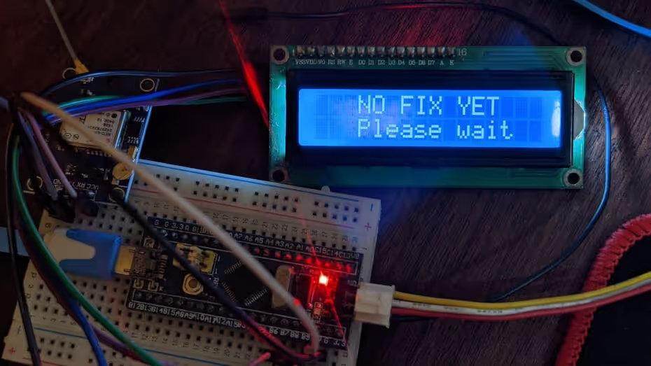
else if ((flagGGA == 1) | (flagRMC == 1))
{
// Instead of clearing the display, it's better if we print spaces.
// This will avoid the "refreshing" part
lcd_put_cur(0, 0);
lcd_send_string(" NO FIX YET ");
lcd_put_cur(1, 0);
lcd_send_string(" Please wait ");
}
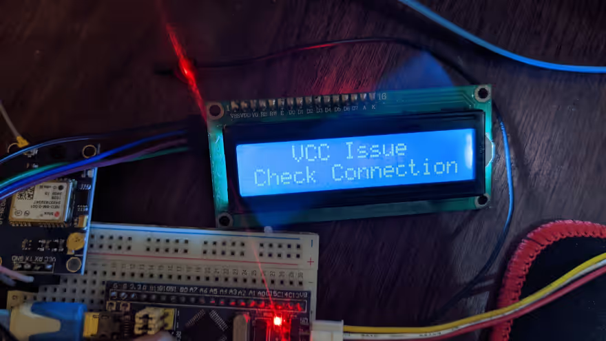
if (VCCTimeout <= 0)
{
VCCTimeout = 5000; // Reset the timeout
//reset flags
flagGGA =flagRMC =0;
// You are here means the VCC is less, or maybe there is some connection issue
// Check the VCC, also you can try connecting to the external 5V
lcd_put_cur(0, 0);
lcd_send_string(" VCC Issue ");
lcd_put_cur(1, 0);
lcd_send_string("Check Connection");
}- Here we check if the GGA and RMC flags are set to 2, indicating that the decoding as success.
- If it is, then we send the time, date and location data to the LCD.
sprintffunction is used to convert the numerical data into the characters.- If the GGA and RMC flags are set to 1, indicating that the GGA and RMC strings were received but the decoding wasn’t successful, we will print the relative information on the display indicating that we haven’t got the fix yet.
- If the
VCC Timeoutis 0, means that the GGA and RMC strings were not detected in the incoming buffer.- This could only mean that either the voltage supply is insufficient, or the connection between the module and controller is faulty.
- We print the relative information on the display again.
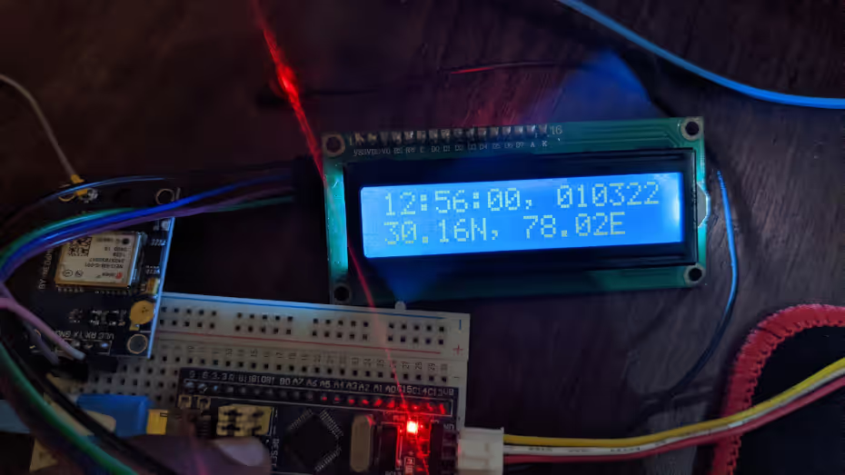
Result
Below are the Pictures of the display in all three cases:
- The VCC provided is 3.3 volts
- The fix is not valid
- Everything is fine


Hi! I already made the UartRingBuffer worked and now I’ve tried to do this but when I debug to see if im receiving data, _rx_buffer is not giving any value. Tried to send string data via Hercules software and I’m receiving it, but not with GPS module. I also tried to connect GPS to U-Center and there I can see NMEA data from my module. I don’t know what happen with my program. Everything configured at 115200 Baudios, GPS+UART. Thanks in advance!
Hi,at this video, you mentioned about previous video about gps module. I can’t find it. I want to know, is there another video about GPS in your site?
The link is literally given in the description of this video.
Anyway here it is https://youtu.be/d81OxWvOUXA
thank you so much
Hi , when I build the project it gives an error which says that there is “multiple definition of `huart1′;” , it is defined at both main.c and UartRingbuffer.c . How can we fix it ?
Hello,if I want to use this code in lpuart how can do it, please reply me thanks.
In the uartRingBuffer.c, have Keyword is “repeat:”. What is it?