How to Read data from Slave Device
This is the 7th tutorial in the AVR series using the xplained mini development board, and today we will continue with the I2C Master series. In this series, we will developing the code for the I2c master across few tutorials, covering the Write and Read operations to the slave device.
We have already covered how to configure and initialize the I2C, and how to write the data to the slave device in the previous tutorials of this series. Today we will see how to read the data from a slave device.
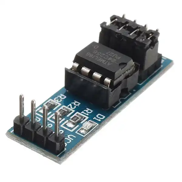
I am going to use the AT24C256 EEPROM for today’s tutorial. This memory device can act an I2C slave and since it has the memory in it, we can store and read back the data from it.
VIDEO TUTORIAL
You can check the video to see the complete explanation and working of this project.
Connection
The connection between the EEPROM and the MCU is shown below.
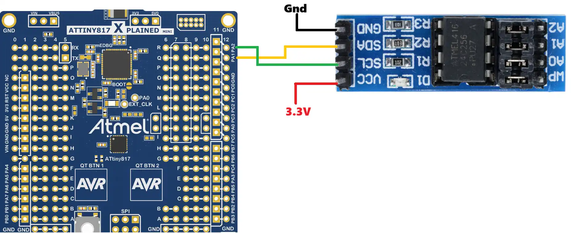
The SCL (clock) pin is connected to the pin PA2 on the MCU and the SDA (data) pin is connected to the pin PA1 on the MCU.
The device is powered by 3.3V from the MCU.
The writing process
Below is the image showing the process of writing the data to a particular memory location of the slave device.
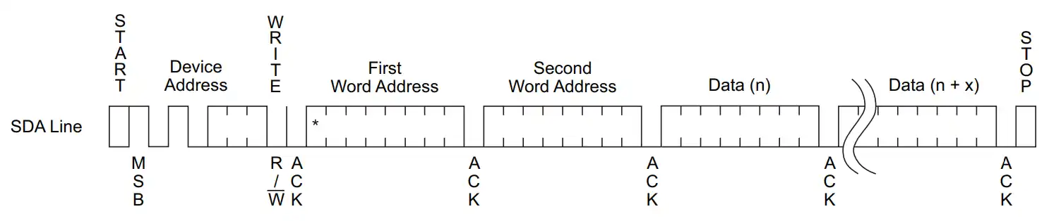
- The master need to send the START condition followed by the Device Address with the write bit.
- Then the master sends the 2 Address bytes. This is the address of the memory location inside the slave device, where the master wants to store the data.
- The master then sends the data bytes and in the end the STOP condition.
We are not writing a separate function for this memory write. Instead we will use the same old function and send the additional data (the memory address bytes) in the main function itself.
uint8_t eepromwrite[20];

eepromwrite[0] = 0;
eepromwrite[1] = 0x25;   // 15 bit address = 0x25 -> {eepromwrite[0] :: eepromwrite[1]} -> {0x0025}
memcpy((uint8_t *)eepromwrite+2, "12345", 5);

I2C_Write(EEPROMADDR, eepromwrite, 7);
_delay_ms(1000);the eepromwrite array holds the data to be sent to the device. We will first load the 2 bytes memory Address (30 & 0) and then store the data (“12345”) into the array.
The I2C_Write function will send the array to the slave device. Below the image shows the output of the write function on the logic analyzer.

We are able to generate the similar conditions as required by the write process of the slave device.
The data will be stored at the particular memory location in the slave device and we would need a read function to read the data from it.
The Read function
The master reads the data from the slave device in a particular sequence. The Read process is shown below.
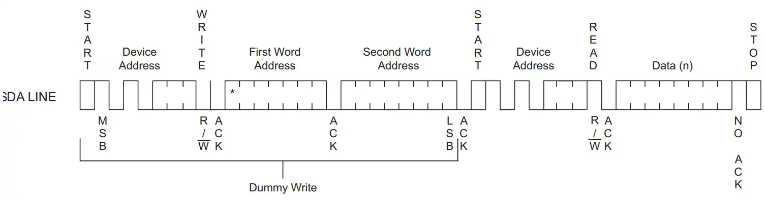
- The master need to send the START condition followed by the Device Address with the write bit.
- Then the master sends the 2 Address bytes. This is the address of the memory location inside the slave device, where the master wants to store the data.
- The master then sends the START condition again, the Repeated Start.
- Then the master sends the Device Address with the Read bit.
- The slave Start transmitting the requested data to the master. The master sends the ACK response after receiving every byte.
- Once the required data has been received, the master send the NACK response with the STOP condition.
Let’s write the Read function as per the above requirement.
uint8_t I2C_Read (uint8_t slaveAddr7b, uint16_t memAddr, uint8_t numMemAddrBytes, uint8_t *buffer, uint8_t size)
{The Read functions takes 5 parameters :
    uint8_t writeaddress = (slaveAddr7b << 1) & 0xFE;
    TWI0.MADDR = writeaddress;  //  send slave address with write bit
while (((TWI0.MSTATUS)&TWI_WIF_bm) == 0); // wait for the write to completeSince the master is need to perform the write operation first, the R/W bit will be set to 0. So we will shift the 7bit slave address to the left by 1 place and add the 0 to the lsb.
Then write the Address to the Address Register (MADDR), and wait for the write operation to complete.
		if (((TWI0.MSTATUS)&(TWI_ACKACT_bm)) == 0)  // if received ACK from slave
{If the address matches with the slave, the slave sends the ACK response and the ACKACT bit in the MSTATUS register will reset to 0. So we will check if this bit before writing the data to the slave.
    if (((TWI0.MSTATUS)& TWI_RXACK_bm) == 0)  // if received ACK from slave
    {
        uint8_t indx =0;

        uint8_t memaddr[numMemAddrBytes];
        for (int i=0; i<numMemAddrBytes; i++)
        {
           memaddr[i] =  (memAddr >> (8*i))&0xFF;
        }

        while ((((TWI0.MSTATUS)&TWI_RXACK_bm) == 0) && (indx < numMemAddrBytes))  // if recvd ACK and index < 2
        {
            TWI0.MDATA = memaddr[indx++];
            while (((TWI0.MSTATUS)&TWI_WIF_bm) == 0);  // wait for the write to complete
        }

        TWI0.MCTRLB = TWI_MCMD_REPSTART_gc;   // send Repeated start
}The indx variable is defined to keep track of number of bytes written to the device. The write is performed in a while loop, which will only run if the master receives the ACK from slave and the indx value is less than the size parameter. This check is performed after writing each byte to the slave device.
The memory address for different slave devices might be either 1 byte in size or 2 bytes. Depending on the memory address size, the master sends the respective address bytes to the slave. Once all the address bytes has been transferred, the master sends the repeated start condition.
    uint8_t readaddress = (slaveAddr7b << 1) | 0x01;
    TWI0.MADDR = readaddress;  //  send slave address with read bit

    if (((TWI0.MSTATUS)& TWI_RXACK_bm) == 0)  // if received ACK from slave
{The master now sends the slave address with the Read bit (‘1’). On receiving the address, the slave device sends the ACK response.
        uint8_t indx =0;
        while (indx < size)
        {
            while (((TWI0.MSTATUS)&TWI_RIF_bm) == 0);  // wait for read operation to complete
            buffer[indx++] = TWI0.MDATA;  // read data from register

            if (indx == size)
            {
                TWI0.MCTRLB = TWI_MCMD_STOP_gc | TWI_ACKACT_NACK_gc;   // send NACK and stop
                return 0;
            }

            else
            {
                TWI0.MCTRLB = TWI_MCMD_RECVTRANS_gc;   // send ACK
            }
        }
}Now the master starts receiving the data. The indx variable will keep track of how many data bytes has been received and the reception will continue as long as the indx variable is less than the data size requested by the master.
The master waits for the Read Interrupt Flag (RIF) in the STATUS register to set. This flag is set when the read operation by the master is complete. Then the data will be copied from the DATA register into the buffer.
Once all the data has been copied, the value of the indx variable will be equal to the size parameter. This is when the master will issue the NACK response followed by the STOP condition.
Otherwise the master will keep ACKnowledging the data.
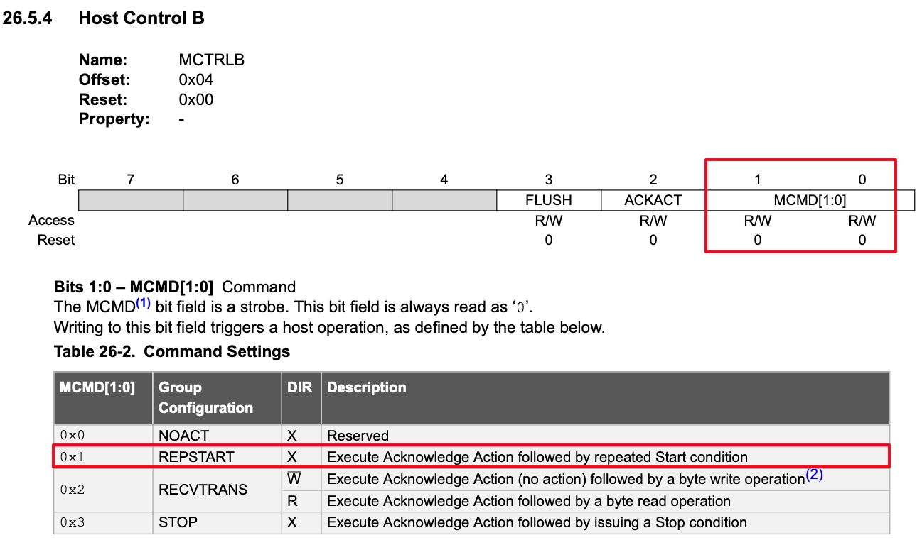
The ACK or NACK response sent by the master depends on the value of the ACKACT bit in the control B register (MCTRLB) in combination with the command bits (MCMD).
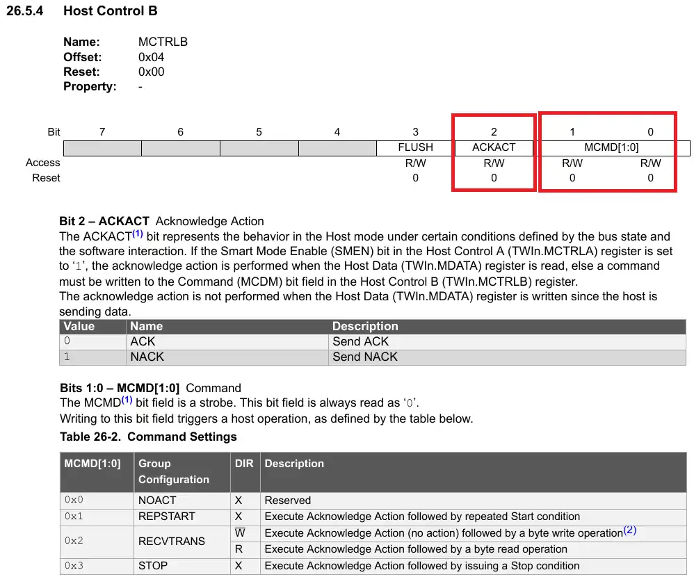
When any of the command bits (MCMD) are sent, the Acknowledge action is also sent along with it. The Acknowledge action depends on the value of the ACKACT bit. If the bit value is 0, the master sends the ACK response, otherwise it sends the NACK response.
To send the Acknowledgement for the byte received, the master simply issues the RECVTRANS command keeping the ACKACT bit to 0. This sends the ACK response to the slave.
To send the NACK response followed by the STOP condition, the master sets the ACKACT bit to 1 and issue the STOP command.
In the main function, after the data has been stored to the memory location, the master will read the data from the same location.
    I2C_Write(EEPROMADDR, eepromwrite, 7);
    _delay_ms(1000);

I2C_Read(EEPROMADDR, 0x0025, 2, eepromread, 5);The master reads the 5 bytes of data from the same memory location (0x0025).
Below is the complete main function.
uint8_t eepromwrite[20];
uint8_t eepromread[20];
int main(void) {
clkInit();
I2C_Init();
_delay_ms(100);
eepromwrite[0] = 0;
eepromwrite[1] = 0x25; // 15 bit address = 0x25 -> {eepromwrite[0] :: eepromwrite[1]} -> {0x0025}
memcpy((uint8_t *)eepromwrite+2, "12345", 5);
    I2C_Write(EEPROMADDR, eepromwrite, 7);
    _delay_ms(1000);

    I2C_Read(EEPROMADDR, 0x0025, 2, eepromread, 5);
while (1) {
}
}Result
Below the image shows the data stored in the eepromread buffer.
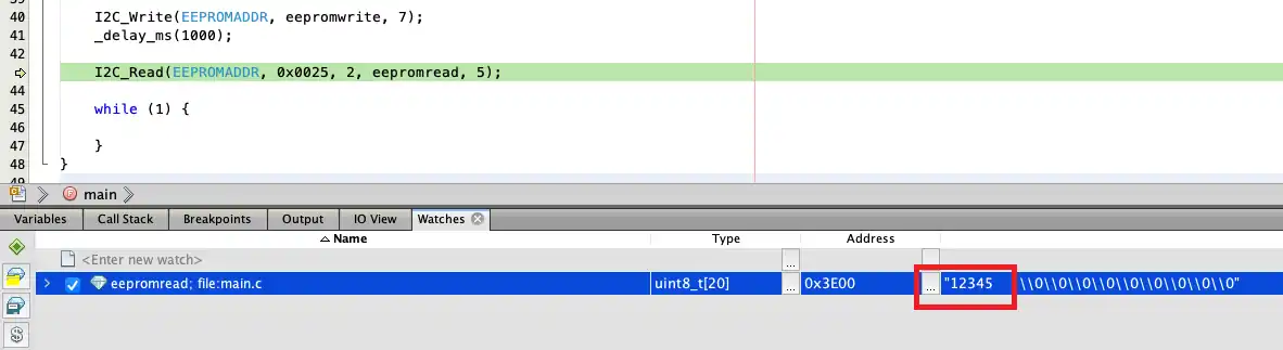
As you can see above, the data received in the eepromread buffer is same as what we stored in the memory.
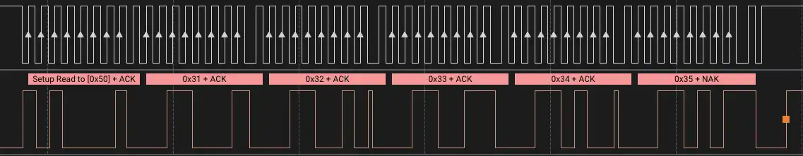
Below the images shows the output on the logic analyzer.
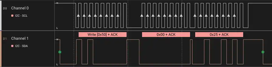
As shown in the first image:
- The master send the START condition followed by the Device Address (0x50) with the write bit.
- Then the master sends the 2 memory Address bytes, 0x00 and 0x25.
- The master then sends the START condition again, the Repeated Start.
Below is the description of second image:
- The master sends the Device Address with the Read bit.
- The slave Start transmitting the requested data to the master. The master sends the ACK response after receiving every byte.
- Once the required data has been received, the master send the NACK response with the STOP condition.

