[vc_row width=”full”][vc_column width=”3/4″][vc_column_text]
TouchGFX #5. Data from UART to UI
This is the 5th tutorial in the STM32 TouchGFX series. I have already covered how to send the data from the MCU to the UI using 2 different methods, i.e. Sample from the GUI task and Sample from other tasks. Today’s tutorial is kind of an extension to the second method, where we will send the data received from the UART to the UI.
So far the data we sent from the MCU only contained numbers or Boolean variables, so the transfer was done simply using the queue. Now the data contains characters, word, sentences or even the paragraph. Sending such data using the simple queue is not possible and therefore we will use the structured queue to send this data.
I have already covered the structured queue in FreeRTOS. You should take a look at it if you haven’t done yet.
TouchGFX Setup
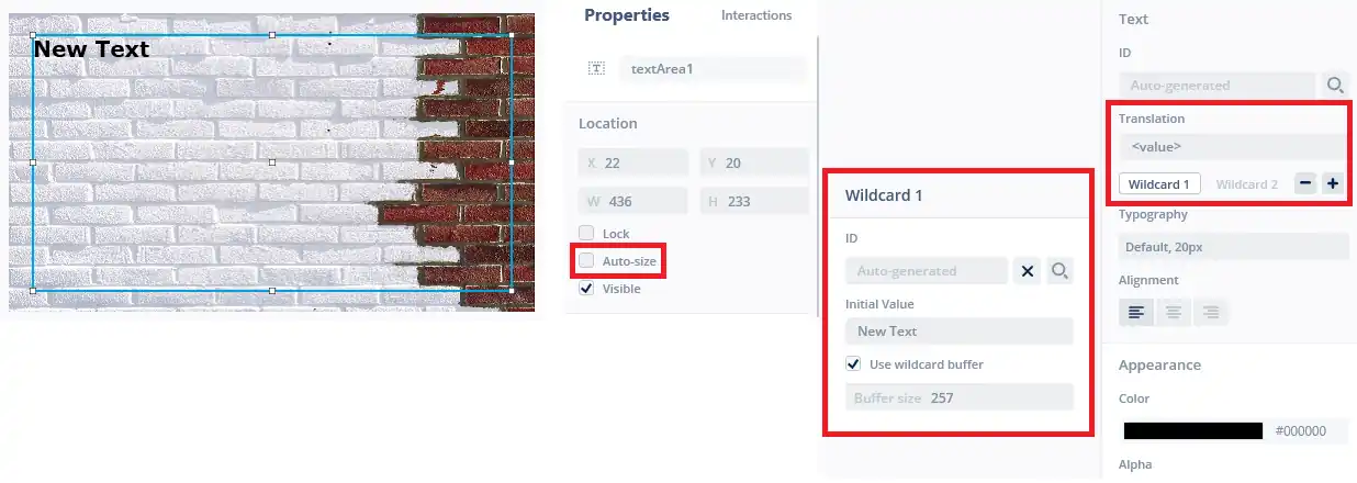
I have added a text Area with a wildcard, whose buffer is defined to hold 257 bytes.
Make sure the auto size is unchecked as we will enable the word wrap in the code.
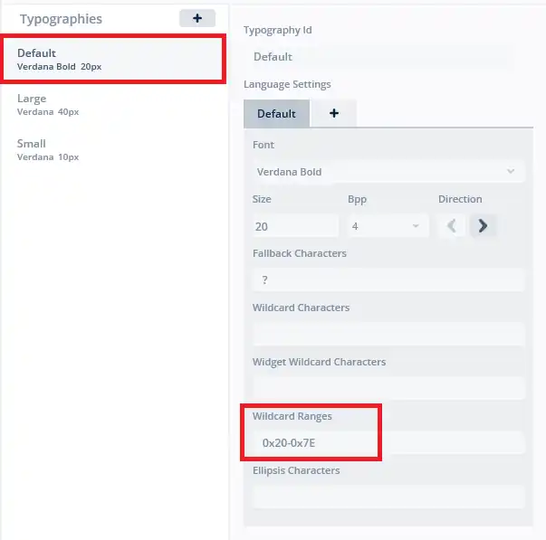
In the typography setup, I have set the wildcard range to be 0x20-0x7E. This covers all the useful ascii characters.
CubeMX Setup
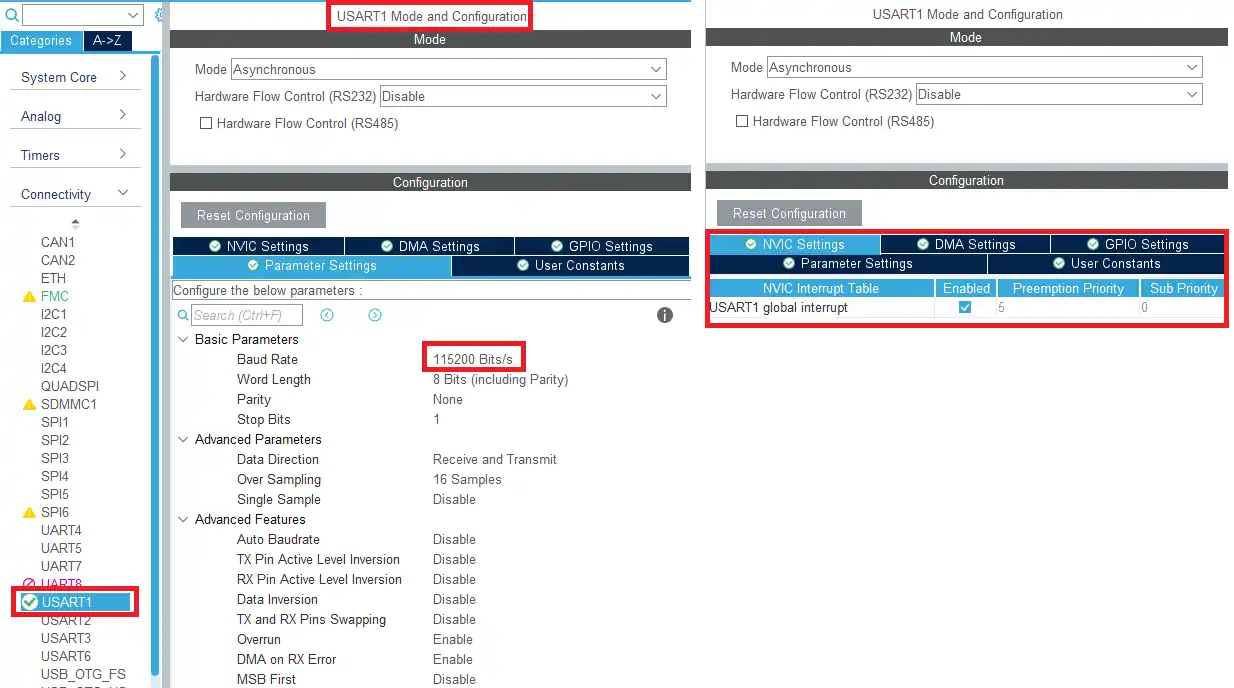
I have enabled USART1 and enabled the interrupt. This is the only configuration for the cubeMX.
some insight into the CODE
typedef struct{
	int size;  // size of the message
	char Data[257];  // The data
}uartData_t;
I have defined a structure in the main header file. This structure will be sent using the queue. The elements are as follows:
- The Size of the message being sent
- The message Data
uint8_t RxData[257];
uartData_t *uartData_q;
I have defined an array (RxData) to store the data received from the UART.
uartData_q is the pointer to the structure we created.
void StartDefaultTask(void *argument)
{
    HAL_UARTEx_ReceiveToIdle_IT(&huart1, RxData, 256);
  for(;;)
  {
    osDelay(100);
  }
}
When the default task runs for the first time, we will call the UART ReceiveToIdle in the interrupt mode. It is set to receive 256 bytes and the received data will be stored in the RxData buffer.
Once the 256 characters has been received or an idle line occurs during the reception, an interrupt will trigger and the RxEvent callback will be called.
void HAL_UARTEx_RxEventCallback(UART_HandleTypeDef *huart, uint16_t Size)
{
RxData[Size] = 'void HAL_UARTEx_RxEventCallback(UART_HandleTypeDef *huart, uint16_t Size)
{
RxData[Size] = '\0';
if (osMessageQueueGetSpace(uartQueueHandle)>0)
{
strncpy (uartData_q->Data, (char *)RxData, Size+1);
uartData_q->size = Size+1;
osMessageQueuePut(uartQueueHandle, &uartData_q, 0, 0);
}
HAL_UARTEx_ReceiveToIdle_IT(&huart1, RxData, 256);
}
';
if (osMessageQueueGetSpace(uartQueueHandle)>0)
{
strncpy (uartData_q->Data, (char *)RxData, Size+1);
uartData_q->size = Size+1;
osMessageQueuePut(uartQueueHandle, &uartData_q, 0, 0);
}
HAL_UARTEx_ReceiveToIdle_IT(&huart1, RxData, 256);
}Inside the Rx event callback function we will send the structure to the queue. The Size parameter of the function represents the number of bytes received via the UART.
- Here first of all I am setting the last byte as the null terminator.
- Then we will enquire for the space available in the queue. The function osMessageQueueGetSpace returns the space available.
- If there is space in the queue we will copy the data from the RxData buffer into the structure.
- We will also update the size parameter of the structure.
- Finally send the address of the structure to the queue.
#ifndef SIMULATOR
#include "main.h"
#include "cmsis_os2.h"
#include <cstring>
extern "C"
{
	extern osMessageQueueId_t uartQueueHandle;
	uartData_t *uartData_r;
}
#endif
void Model::tick()
{
#ifndef SIMULATOR
	if (osMessageQueueGetCount(uartQueueHandle)>0)
	{
		if (osMessageQueueGet(uartQueueHandle, &uartData_r, 0, 0)== osOK)
		{
			strncpy (RData, uartData_r->Data, uartData_r->size);
			modelListener->uart_Data (RData);
		}
	}
#endif
}
The data is received in the Model::tick() function as follows:
- Here we will check if there is some message in the queue. The function osMessageQueueGetCount returns the number of pending messages in the queue.
- If there is some message, osMessageQueueGet will receive the structure from the queue and store it in the uartData_r.
- uartData_r is the pointer to the structure we defined in the main header file.
- After receiving the structure, we will extract the data from it.
- strncpy function will copy the data from the structure to the into the RData buffer we created.
- Finally the data will be sent to the presenter as the parameter of the function uart_Data.
void Screen1Presenter::uart_Data (char *data)
{
	view.uart_Data (data);
}
Inside the Presenter source file, we will call the same function in the view.
void Screen1View::uart_Data (char *data)
{
	textArea1.setWideTextAction(touchgfx::WIDE_TEXT_WORDWRAP);
	Unicode::strncpy(textArea1Buffer, data, TEXTAREA1_SIZE);
	textArea1.invalidate();
}
Inside the view source file we will finally display the data on the UI.
- Here we will first enable the word wrap. The function setWideTextAction enables the word wrap.
- Then copy the data from the data buffer into the text Area buffer.
- Finally invalidate the text area, so the changes can take effect.
Result
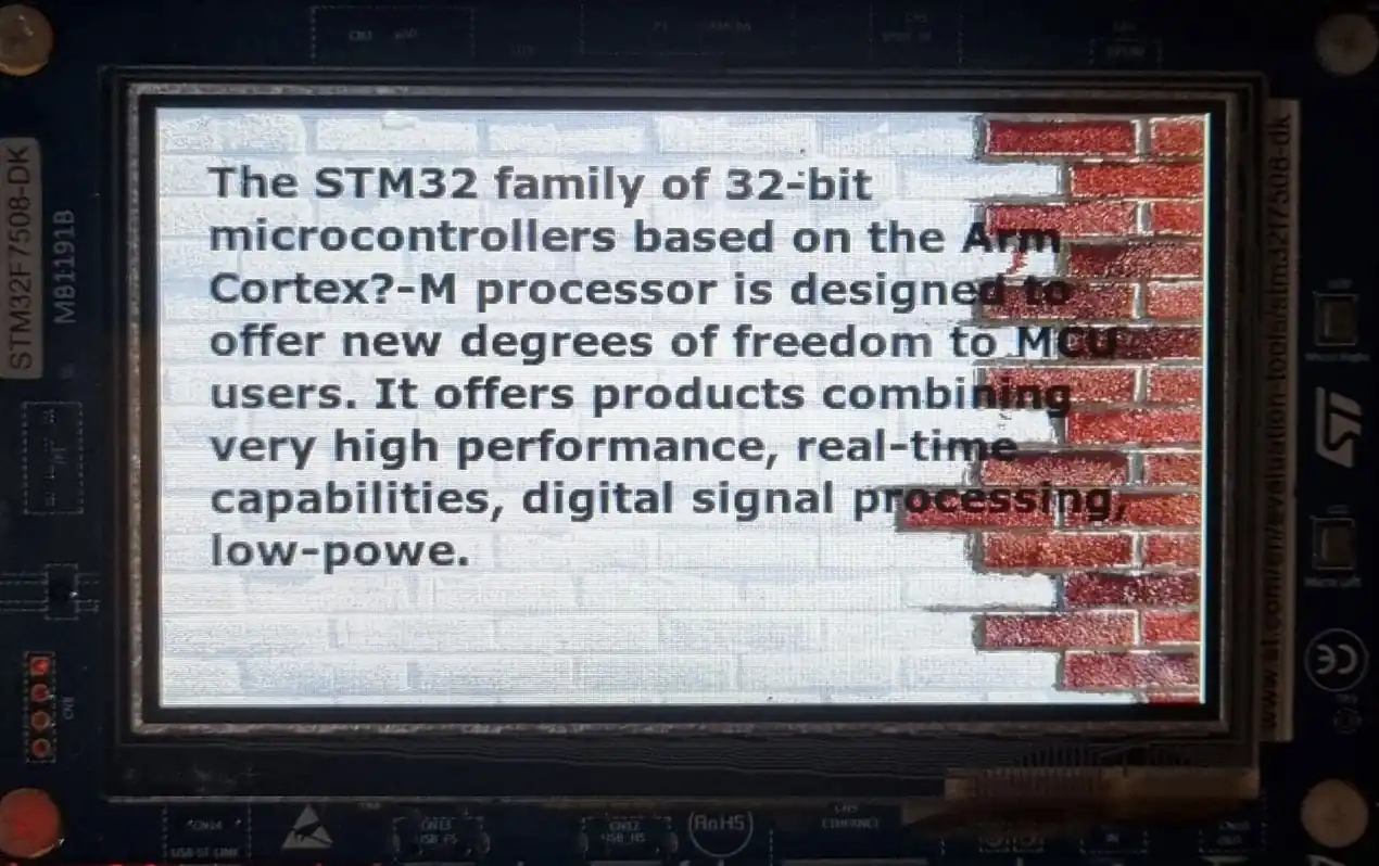
Below is the image showing the text being displayed on the UI. This text was sent via the UART.
Check out the Video Below
Info
You can help with the development by DONATING Below.
To download the project, click the DOWNLOAD button.
[/vc_column_text][/vc_column][vc_column width=”1/4″ offset=”vc_hidden-sm vc_hidden-xs”][vc_column_text]
[/vc_column_text][/vc_column][/vc_row]










In main there is the declatation:
uartData_t *uartData_q
but the uartData_q pointer is used without being allocated.
Just got stuck in the same place…