How to Configure UART & Send Data
This is the 3rd tutorial in the AVR series using the xplained mini evaluation board, and today we will cover the UART peripheral. The USART stands for universal synchronous/asynchronous receiver/transmitter, but we will only focus on the Asynchronous part so we are only going to cover the UART.
UART is a big topic in itself to cover, hence we will cover it in multiple tutorials. Today we will start with the configuration and how to send the data over UART. Sending the data is easier compared to the receiving data, this is because we already know how much data we are sending. This is why we will start with the sending first.
I am going to use a serial monitor on the computer, which will display the data sent by the MCU.
The xplained mini development board supports the virtual com port, which means that we don’t need an external hardware to communicate to the computer via the UART. We can simply use the USB used for programming/debugging to send and receive the data from the computer.
Below is the image showing the virtual com port gets detected on the computer when the USB is connected to the board.
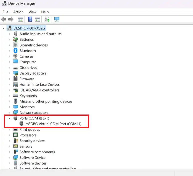
As you can see above, the mEDBG Virtual COM Port is connected to the COM11.
If you still want to use any USB to UART converter, the connection for the same is shown below.
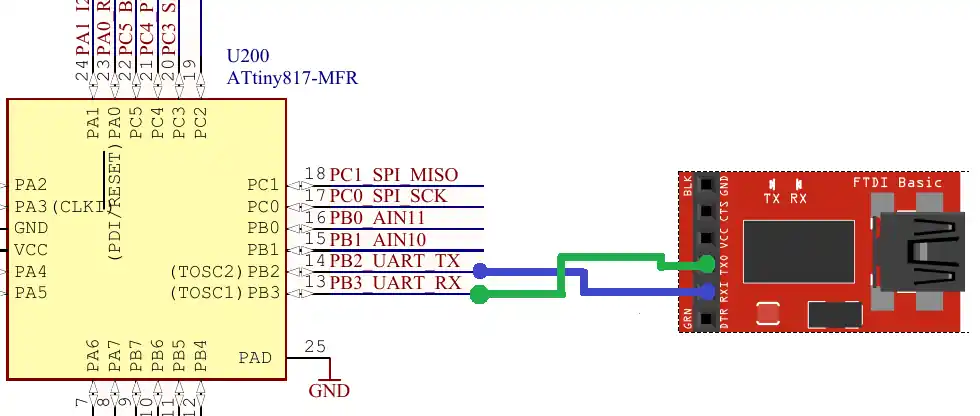
The TX pin from the MCU connects to the RX pin of the module, and the RX pin from the MCU connects to the TX pin of the module. The UART connection is always made in the cross. Also note that the pin PB2 is the TX pin, which we will set as the output and the pin PB3 is the RX pin which we will set as the input.
VIDEO TUTORIAL
You can check the video to see the complete explanation and working of this project.
Configure the UART
We will start with the USART Control B Register.
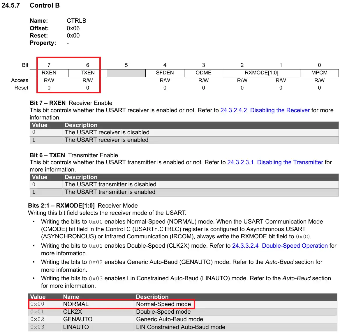
The Bits 6 and 7 of this register are used to enable/disable the Transmitter and Receiver for the UART. We will enable these bits so to enable the Transmitter and Receiver. Also the bits [2:1] sets the Receiver in the different available modes. We will leave these bits to 0 to set the receiver in the normal mode.
The reset of the bits of this register are kept to their default states, i.e. diabled.
USART0.CTRLB = (1<<7)|(1<<6); // RX & TX enable, Normal mode, SOF disabledThe next register is USART Control C Register.
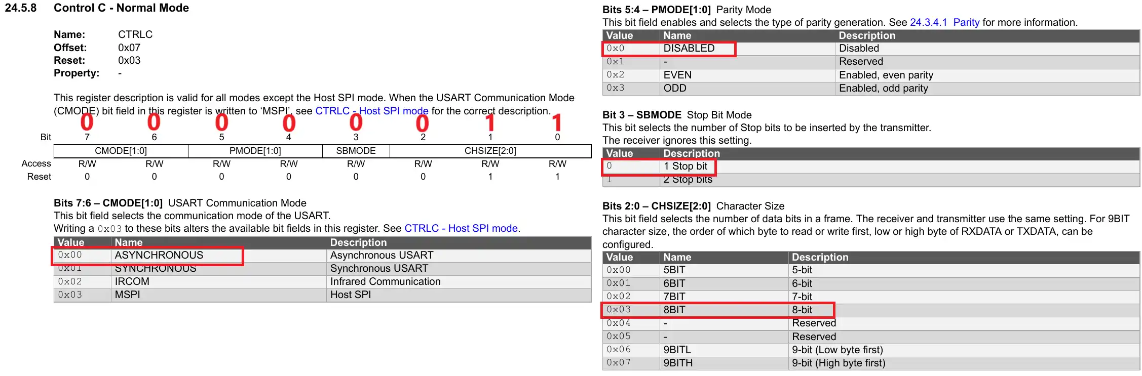
Here we are setting the commonly used UART configuration, which consists of 8 Data bit with 1 stop bit and no Parity. The UART mode is set to asynchronous mode.
The final value for the Register is 0x03.
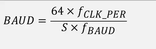
USART0.CTRLC = 0x03; // Asynch mode, no parity, 1 stop bit, 8 data bitsThe next register is the Baud Register. This is a 16 bit register and the value in this register decides the baud rate of the UART. Below the image shows the formula to calculate the Baud Register value for the desired baud rate.
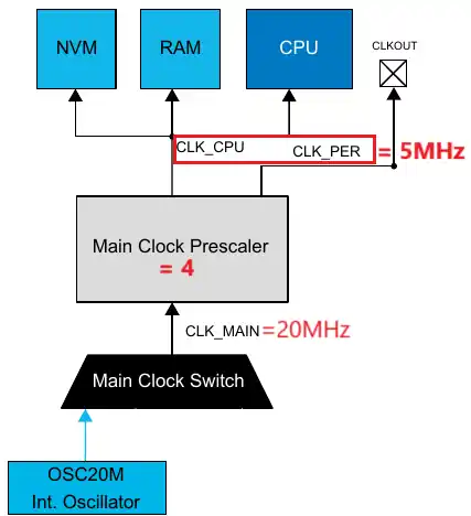
Our clock is configured to use the 20MHz internal oscillator with the prescaler of 4. This reduces the clock to 5MHz. The same clock is being used by the CPU and the peripheral (CLK_PER). This is shown in the image below.
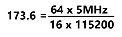
For the peripheral clock of 5MHz and the desired baud rate of 115200, the Baud register value calculation is shown below.
The parameter S is the number of samples per bit, and for the Asynchronous normal mode, it’s value is 16.
We can not input the decimal value in a 16 bit register, so we will input the value 174 into it.
USART0.BAUD = 174;We will use the STATUS Register to monitor if the data transfer has been finished or not.
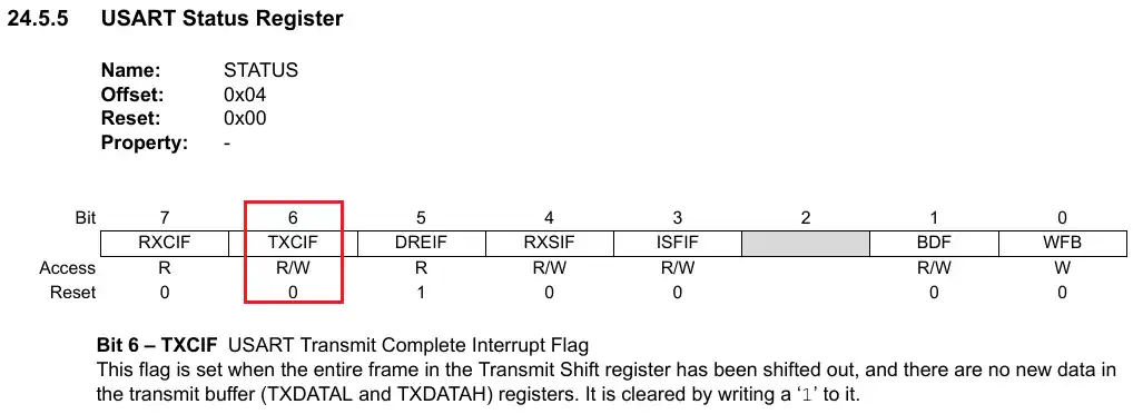
The bit 6 of this register (TXCIF) sets when the data in the TXDATA register has been shifted out. During the configuration, we will clear this bit by writing a 1 into it.
USART0.STATUS |= 1<<6; // clear TXCIF flagNow we will configure the pins for the UART. The pin PB2 is the UART TX pin and it must be set as the output, while the pin PB3 is the UART RX pin and it must be set as the input.
PORTB.DIR = 0x04; //0b00000100 -> PB2->OUT, PB3->INThis completes the UART configuration. Below is the final code that contains the registers configuration explained above.
void uartInit (void)
{
	USART0.CTRLB = (1<<7)|(1<<6);  // RX & TX enable, Normal mode, SOF disabled
	USART0.CTRLC = 0x03;  // Asynch mode, no parity, 1 stop bit, 8 data bits
	USART0.BAUD = 174;
	USART0.STATUS |= 1<<6; // clear TXCIF flag

	PORTB.DIR = 0x04;  // PB2->OUT, PB3->IN

}Transmit Data
Transmit a single Byte
The TXDATAL (Low Byte) and TXDATAH (High Byte) Registers are used to transmit the data.
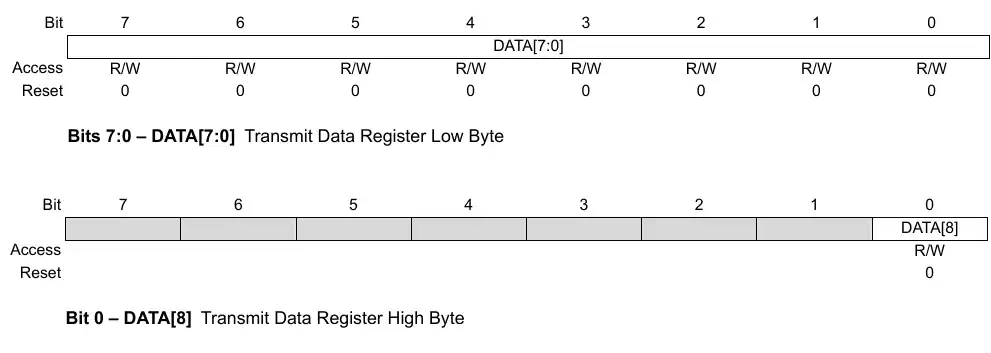
The TXDATAH register is only used when we use 9 data bits in the configuration. But we have configured the UART to use 8 Data bits, so we will only use the TXDATAL.
void uartsendByte (uint8_t data)
{
  USART0.TXDATAL = data;
  while(((USART0.STATUS)&(1<<6)) == 0);  // wait for the TXCIF bit to set
  USART0_STATUS |= (1<<6);	// clear TXCIF flag
}To Transmit a Byte of data, we will simply copy the Data into the TXDATAL register and then wait for the TXCIF bit in the status register to set. This bit will confirm that the data has been transmitted and we can then load a new data into the register.
Transmit a string
To transmit an entire string, call the byte transmit function as many times as the length of the string.
void uartSendStr (char *str)
{
	while (*str)
	{
		uartsendByte(*str++);
	}
}The main function
char data[] = "hello world from AVR\r\n";

int main(void)
{
  clkInit();
  uartInit();
  while(1)
  {
      uartSendStr(data);
      _delay_ms(1000);
  }
}In the main function, we will first initialize the clock, and then initialize the UART. Inside the while loop, we will send the string every 1 second.
Result
Below the image shows the output of the above code on the serial terminal.
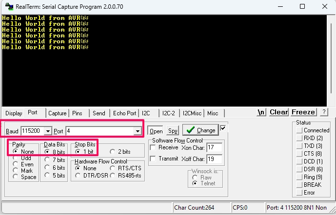
You can see the string is being received on the terminal. Also note the terminal is configured with the same settings which we set for the UART, i.e. 115200 baud with 8 Data bits, 1 Stop bit and no Parity.

