
Home ▸ ESP32 ▸ UART Tutorials ▸
Updated On: May 5, 2026
ESP32 UART LED Control via UART2 with ESP-IDF
In ESP32 UART Part 1 we covered how to configure UART, transmit data from the ESP32, and receive it on a PC. This tutorial takes the next step: using UART2 as a command interface to control a physical LED, with the ESP32 echoing every command back to your serial terminal.
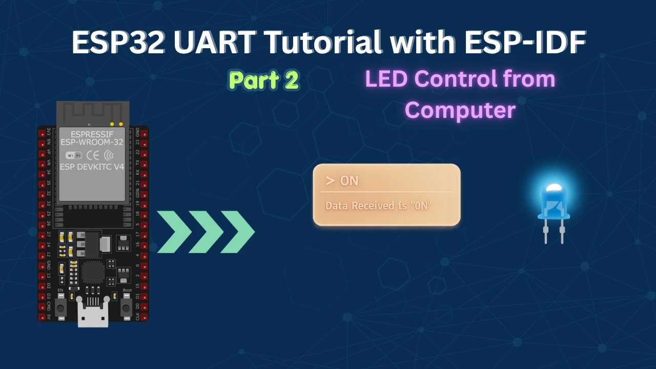
The project uses two separate FreeRTOS tasks, one for receiving and one for transmitting, co-ordinated through task suspension and resumption. When you send ON via a serial terminal, the LED turns on and the ESP32 replies Data Received is 'ON'. Send OFF and the LED turns off with a matching echo.
Hardware: ESP32 dev board · LED + current-limiting resistor
Software: ESP-IDF · Eclipse IDE · FreeRTOS (included with ESP-IDF)
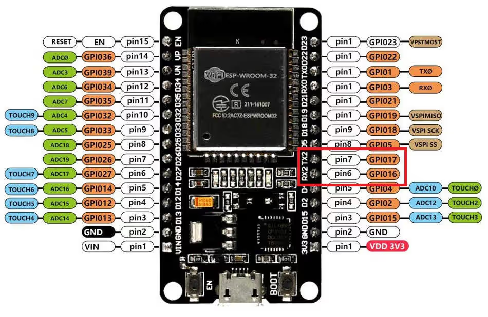
UART instance: UART2 · TX → GPIO 17 · RX → GPIO 16 · LED → GPIO 13
UART series:
- Part 1 — Configure, Transmit & Receive
- Part 2 — LED Control (this tutorial)
- Part 3 — Receive Using UART Events
More ESP32 tutorials:
How It Works — ESP32 UART2 Overview
The ESP32 has three hardware UART controllers: UART0, UART1, and UART2. UART0 is reserved for the default ESP-IDF console and debug log output — it is tied to the USB-to-serial bridge you use for flashing. To keep application data cleanly separated from log traffic, this tutorial uses UART2.
The overall flow is straightforward. Two FreeRTOS tasks run concurrently:
- The RX task polls UART2 for incoming data. When a command arrives it null-terminates the buffer, compares it against
"ON"and"OFF", drives the LED GPIO accordingly, and resumes the TX task. - The TX task wakes up, formats an echo string (
"Data Received is 'ON'"), writes it back over UART2, and immediately suspends itself again until the next command.
This suspend/resume pattern means the TX task consumes zero CPU time between commands — a clean, low-overhead approach you can extend to any command-response protocol.
Definitions and Pin Mapping
All pin and buffer definitions sit at the top of the file:
#define UART_NUM    UART_NUM_2
#define TXD_PIN     (GPIO_NUM_17)
#define RXD_PIN     (GPIO_NUM_16)

uint8_t RxData[128];
static const int RX_BUF_SIZE = 128;

#define LED_NUM     GPIO_NUM_13

TaskHandle_t txTaskHandle;A few points worth noting:
UART_NUMis a convenience macro. Every ESP-IDF UART function that requires a port number accepts this, keeping a future port change to a one-line edit.RxDatais declared globally so both the RX task (which writes into it) and the TX task (which reads from it to build the echo) share the same buffer without passing a pointer between tasks.RX_BUF_SIZEand theRxDataarray are both 128 bytes — matching the ESP32 hardware UART FIFO length (SOC_UART_FIFO_LEN = 128).txTaskHandleis the FreeRTOS handle for the TX task. The RX task needs this handle to callvTaskResume()— it cannot useNULLto resume a different task.
LED GPIO Configuration
void ledConfig(void)
{
    gpio_reset_pin(LED_NUM);
    gpio_set_direction(LED_NUM, GPIO_MODE_OUTPUT);
}gpio_reset_pin() clears any previous mux configuration and input/output settings on the pin, returning it to a known default state. gpio_set_direction() then configures it as a push-pull output so gpio_set_level() can drive it high or low.
UART2 Wiring & Initialisation
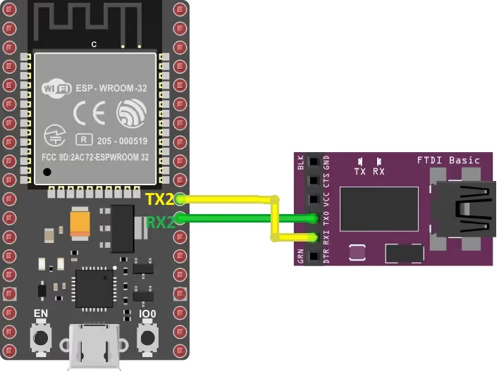
Connect the ESP32 to a USB-to-TTL adapter using GPIO 16 (RX) and GPIO 17 (TX). Remember to cross the wires: ESP32 TX → adapter RX, ESP32 RX → adapter TX. Connect the LED between GPIO 13 and GND through a 220–330 Ω resistor.
| ESP32 Pin | Connects To | Role |
|---|---|---|
| GPIO 17 | USB-TTL RX | UART2 TX |
| GPIO 16 | USB-TTL TX | UART2 RX |
| GPIO 13 | LED anode (via resistor → GND) | LED output |
| GND | USB-TTL GND | Common ground |
UART initialisation is handled inside init() and follows three mandatory steps in order: install the driver, configure parameters, assign pins.
void init(void)
{
    const uart_config_t uart_config = {
        .baud_rate  = 115200,
        .data_bits  = UART_DATA_8_BITS,
        .parity     = UART_PARITY_DISABLE,
        .stop_bits  = UART_STOP_BITS_1,
        .flow_ctrl  = UART_HW_FLOWCTRL_DISABLE,
        .source_clk = UART_SCLK_DEFAULT,
    };

    uart_driver_install(UART_NUM, RX_BUF_SIZE * 2, 0, 0, NULL, 0);
    uart_param_config(UART_NUM, &uart_config);
    uart_set_pin(UART_NUM, TXD_PIN, RXD_PIN, UART_PIN_NO_CHANGE, UART_PIN_NO_CHANGE);
}Step 1 — uart_driver_install
uart_driver_install(UART_NUM, RX_BUF_SIZE * 2, 0, 0, NULL, 0);This allocates the internal UART driver buffers and interrupt. The parameters are:
| Parameter | Value Used | Explanation |
|---|---|---|
uart_port_t | UART_NUM_2 | The UART controller to install the driver on. |
rx_buffer_size | RX_BUF_SIZE * 2 = 256 | Size of the software RX ring buffer. Must be larger than the hardware FIFO length (128 bytes). Doubling it prevents data loss if the task is briefly delayed. |
tx_buffer_size | 0 | No software TX buffer. uart_write_bytes() will block until all bytes are written to the hardware FIFO. Acceptable here because the echo string is short. |
queue_size | 0 | No event queue. This tutorial uses polling, not event-driven reception. |
uart_queue | NULL | No queue handle needed. |
intr_alloc_flags | 0 | Default interrupt allocation flags. |
Step 2 — uart_param_config
uart_param_config(UART_NUM, &uart_config);Applies the frame format defined in uart_config: 8 data bits, no parity, 1 stop bit (8-N-1) at 115200 baud. Hardware flow control is disabled since no RTS/CTS lines are wired. UART_SCLK_DEFAULT selects the APB clock as the UART clock source, which is the correct choice for most ESP32 applications.
Step 3 — uart_set_pin
uart_set_pin(UART_NUM, TXD_PIN, RXD_PIN, UART_PIN_NO_CHANGE, UART_PIN_NO_CHANGE);Maps the UART2 peripheral to physical GPIO pins. The last two arguments are the RTS and CTS pins; passing UART_PIN_NO_CHANGE (value -1) skips them since flow control is disabled.
Code: RX/TX Tasks, Command Parsing and Results
The TX Task
static void tx_task(void *arg)
{
    uint8_t *data = (uint8_t *)malloc(150);
    while (1)
    {
        int len = sprintf((char *)data, "Data Received is '%s' \n", RxData);
        uart_write_bytes(UART_NUM, data, len);
        vTaskSuspend(NULL);  /* suspend self; RX task will resume us */
    }
    /* free(data) is intentionally unreachable — this task runs indefinitely */
}The TX task is designed to fire once per received command, transmit an echo, and go back to sleep. Here is how it works:
malloc(150)allocates a 150-byte heap buffer for the outgoing string. 150 bytes is generous enough to hold any echo of a short command without risk of overflow.sprintf()formats the echo string, embedding the contents of the globalRxDatabuffer. This is whyRxDatamust be global — the TX task reads it directly.uart_write_bytes(UART_NUM, data, len)writeslenbytes to the UART2 TX FIFO. Because the TX ring buffer size is 0 (no software buffer), this call blocks until all bytes have been loaded into the hardware FIFO.vTaskSuspend(NULL)suspends the calling task itself. The task sits here, consuming no CPU, until the RX task callsvTaskResume(txTaskHandle). At that point execution resumes immediately after this line — which brings the loop back tosprintf()to process the next command.
Note on free():
The free(data) call after the while(1) loop is unreachable. This is a benign code pattern common in FreeRTOS tasks that are intended to run forever. If you ever need to delete this task cleanly, call vTaskDelete(NULL) inside the loop before the suspend, and move free(data) to the code path that deletes the task.
The RX Task
static void rx_task(void *arg)
{
    int ledState = 0;
    static const char *RX_TASK_TAG = "RX_TASK";
    esp_log_level_set(RX_TASK_TAG, ESP_LOG_INFO);

    while (1)
    {
        const int rxBytes = uart_read_bytes(UART_NUM, RxData, RX_BUF_SIZE,
                                            200 / portTICK_PERIOD_MS);
        if (rxBytes > 0)
        {
            RxData[rxBytes] = 0;  /* null-terminate for strcmp */

            if      (strcmp((char *)RxData, "ON")  == 0) ledState = 1;
            else if (strcmp((char *)RxData, "OFF") == 0) ledState = 0;

            gpio_set_level(LED_NUM, ledState);
            vTaskResume(txTaskHandle);
            ESP_LOGI(RX_TASK_TAG, "Read %d bytes: '%s'", rxBytes, RxData);
        }
    }
}The RX task is the heart of this project. Step by step:
uart_read_bytes — polling with timeout
uart_read_bytes() waits up to 200 ms for data to arrive in the RX ring buffer. Its parameters are:
| Parameter | Value Used | Explanation |
|---|---|---|
uart_port_t | UART_NUM_2 | Which UART to read from. |
buf | RxData | Destination buffer for the received bytes. |
length | RX_BUF_SIZE (128) | Maximum bytes to read in one call. |
ticks_to_wait | 200 / portTICK_PERIOD_MS | Timeout: if fewer than length bytes arrive within 200 ms, the function returns with however many bytes were received. |
The function returns the actual number of bytes received, stored in rxBytes. If the timeout elapses with nothing received, it returns 0 and the loop simply repeats.
Null-termination
RxData[rxBytes] = 0 places a null terminator after the last received byte, converting the raw byte array into a proper C string. This is essential before passing it to strcmp(), which expects null-terminated input.
Command parsing
strcmp() returns 0 when the two strings match exactly. So:
- If
RxDatais exactly"ON",ledStateis set to 1. - If
RxDatais exactly"OFF",ledStateis set to 0. - Any other input leaves
ledStateunchanged and the LED stays in its current state. The echo is still sent, which helps with debugging unexpected input.
GPIO and task co-ordination
gpio_set_level(LED_NUM, ledState) drives GPIO 13 high or low. Then vTaskResume(txTaskHandle) wakes the TX task — it will format and send the echo on its next cycle. Finally, ESP_LOGI() prints a log line to the console for debugging.
app_main — Initialisation and Task Creation
void app_main(void)
{
    init();
    ledConfig();
    xTaskCreate(rx_task, "uart_rx_task", 1024 * 2, NULL,
                configMAX_PRIORITIES - 1, NULL);
    xTaskCreate(tx_task, "uart_tx_task", 1024 * 2, NULL,
                configMAX_PRIORITIES - 2, &txTaskHandle);
}init() installs the UART driver and configures UART2. ledConfig() sets up GPIO 13 as an output. Then two FreeRTOS tasks are created:
| Task | Stack | Priority | Handle stored? |
|---|---|---|---|
rx_task | 2048 bytes | configMAX_PRIORITIES - 1 (highest) | No — NULL passed |
tx_task | 2048 bytes | configMAX_PRIORITIES - 2 | Yes — stored in txTaskHandle |
The RX task runs at the highest priority so it processes incoming data before anything else. The TX task is one priority level lower. Its handle is stored in txTaskHandle because the RX task needs it to call vTaskResume(). Note that the last parameter of the rx_task creation is NULL because no other task needs to resume or delete it.
Test Results
Open a serial terminal (115200 baud, 8-N-1) connected to the USB-TTL adapter on UART2. Type ON and press Enter — the LED lights up and the terminal prints:
Data Received is 'ON'Type OFF and press Enter — the LED goes off and the terminal prints:
Data Received is 'OFF'You can see the working in the GIF below:

ESP32 UART LED Control via UART2 — Video Tutorial
This video walks through the complete implementation of UART-based LED control on the ESP32 using ESP-IDF. We configure UART2 on GPIO 16/17, write separate RX and TX FreeRTOS tasks, parse ON/OFF commands, and verify LED toggling with a serial terminal echo.
ESP32 UART with ESP-IDF: Frequently Asked Questions
Conclusion
In this tutorial you built a complete UART command interface on the ESP32 using ESP-IDF. UART2 was initialised with a 256-byte ring buffer and 8-N-1 framing at 115200 baud. Two FreeRTOS tasks handle reception and transmission independently — the TX task suspends itself after every echo and only wakes when the RX task signals it, making the design efficient and easy to reason about.
The command parsing pattern used here — null-terminating the receive buffer and comparing with strcmp() — is the correct approach for fixed-string commands. You can scale it directly: add more else if branches for commands like TOGGLE or BLINK, or swap the chain for a lookup table once the command set grows.
Three natural next steps from here:
- Switch from polling to UART event-driven reception (Part 3) to reduce CPU overhead and respond to data immediately rather than on a 200 ms poll cycle.
- Combine UART control with an I2C sensor like the MPU6050 — use UART commands to request sensor readings on demand.
- Explore ADC input and report sampled values back over UART in response to a
READcommand.
Download ESP32 UART LED Control (UART2) Project Files
Complete ESP-IDF project with UART2 configuration, RX/TX FreeRTOS tasks, LED GPIO control, and ON/OFF command parsing. Free to download — support the work if it helped you.
Browse More ESP32 UART Tutorials

Subscribe
Login
0 Comments
Newest

