Home ▸ STM32 Tutorials ▸
Updated On: January 9, 2026
Interfacing DHT22 with STM32: Accurate Temperature and Humidity Measurement
Measuring temperature and humidity using the DHT22 sensor with STM32 microcontrollers is a reliable and efficient way to gather environmental data in embedded systems.
In this tutorial, we will interface the DHT22 sensor with an STM32 board using STM32CubeIDE and the HAL libraries. The DHT22 provides high accuracy and a digital output, making it ideal for real-time monitoring applications.
We’ll start by configuring a timer to generate accurate microsecond delays, which are essential for reliable communication with the sensor. Then, we’ll look at how to send the start signal, wait for the sensor’s response, and read the 40-bit data stream. Finally, we’ll extract the temperature and humidity values from the received data and verify the checksum to ensure data integrity.
You can check the DHT22 datasheet here.
prerequisites:
- We have already covered how to generate the delay in microseconds using timer in STM32. Today we will utilize the delay in microseconds to interface the DHT22 temperature and Humidity sensor with STM32.
- You can also check out the similar tutorials covering how to interface the DHT11 sensor with STM32 and Interface DS18B20 sensor with STM32.
- We will display the results on LCD16x2, which is connected via the I2C. You can check the tutorial Interface the LCD via I2C with STM32.
If you are not able to get DHT11 or DHT22 values, Here is another method you can use. This one is unified for both the sensors. No setup needed for timer and all. Just select the data pin as output and you are done. you need to configure the DHT TYPE in DHT.c file. Download it from https://controllerstech.com/wp-content/uploads/2020/06/DHT_11_22_DWT.zip
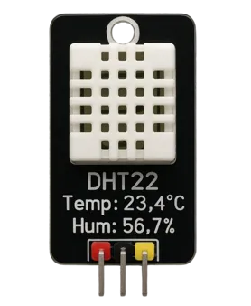
Introducing DHT22 Temperature & Humidity Sensor
The DHT22, also known as AM2302, is a popular digital sensor used for measuring both temperature and relative humidity. It offers high accuracy, low power consumption, and a simple single-wire interface, making it ideal for embedded systems, weather stations, and IoT applications. The sensor combines a capacitive humidity sensor and a thermistor to provide reliable readings in various environments.
Its key features are:
- High Accuracy: ±0.5 °C for temperature and ±2% for humidity, suitable for precise environmental monitoring.
- Wide Operating Range: Measures temperature from –40 °C to 80 °C and humidity from 0% to 100% RH.
- Digital Output: Sends data in a 40-bit digital format over a single GPIO pin, reducing complexity.
- Low Power Consumption: Operates efficiently, making it suitable for battery-powered or low-power applications.
Why Choose DHT22 Over Other Sensors?
- Better Accuracy: DHT22 offers ±0.5 °C temperature and ±2% humidity accuracy, which is significantly higher than DHT11’s ±2 °C and ±5% accuracy.
- Wider Measurement Range: It supports a broader temperature range (–40 °C to 80 °C) and full 0–100% relative humidity, making it suitable for harsh or dynamic environments.
- Longer Sensor Lifespan: With proper handling, the DHT22 has a longer operational lifespan and maintains calibration better over time compared to low-cost alternatives.
- Higher Resolution Output: It provides more detailed readings with 0.1°C and 0.1% RH resolution, which is useful for applications requiring fine-grained environmental data.
DHT11 vs DHT22 which one is better ?
The table below shows the comparison between the DHT11 an DHT22.
| Feature | DHT11 | DHT22 |
|---|---|---|
| Temperature Range | 0°C to 50°C | -40°C to +80°C |
| Temperature Accuracy | ±2°C | ±0.5°C |
| Humidity Range | 20% to 90% RH | 0% to 100% RH |
| Humidity Accuracy | ±5% RH | ±2–5% RH |
| Sampling Rate | 1 reading per second (1Hz) | 0.5 reading per second (2s interval) |
| Operating Voltage | 3.3V to 5V | 3.3V to 6V |
| Data Format | Digital (1-wire) | Digital (1-wire) |
| Cost | Lower cost | Slightly higher |
| Size | Smaller | Slightly larger |
| Use Case | Basic hobby projects | Projects needing better accuracy |
The choice is simple:
- Choose DHT11 for budget-friendly, basic monitoring.
- Choose DHT22 when you need better accuracy, wider range, and more reliability.
How does the DHT22 communicate ?
The DHT22 uses one wire to communicate to the MCU. Therefore it is a very time sensitive device. Below are the timing diagrams from the DHT22 datasheet, used in different processes.
Initialization
Below the image shows the START condition.
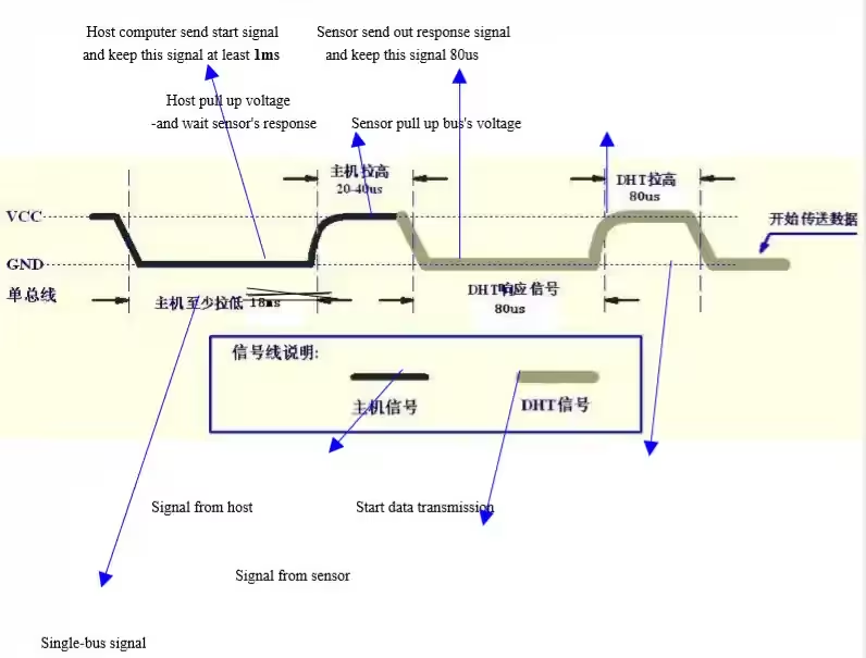
Here the Black line is the signal from the microcontroller and the Grey line is the signal from the DHT22.
In order to initialize the sensor, we have to pull the data line LOW for at least 1ms, and pull it HIGH for around 20-40 us.
On receiving the start signal, DHT22 will indicate it’s presence by pulling the line low for 80us and than high for 80us.
Note:
You might need to connect pull-up resistance to the data line or else DHT22 will not be able to pull it HIGH.
To initialize the sensor, the steps are as follows:-
- Set the pin (data) as output.
- Pull the pin low and wait for > 1 ms.
- Pull the pin high and wait for 30 us.
- Release the pin by setting it as input.
DHT22 will now send the response as you can see in the figure above. To check the response, steps are as follows:-
- Wait for 40us.
- Check if the pin is low, than wait for 80 us. This will be a total delay of 120 us and the pin should be high now.
- Check if the pin is high. If it is, then the response is OK.
- Now wait for the pin to go LOW.
DATA Transmission
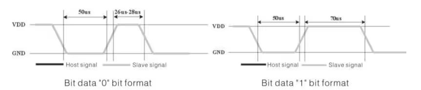
Now DHT22 will send 40 bits of data. Each bit’s transmission begins with low-voltage-level that last 50 us, the following high-voltage-level signal’s length decides whether the bit is “1” or “0“.
- If the length of high-voltage-level is around 26-28 us, the bit is “0”
- And if the length is around 70 us, than the bit is “1”
The 40 bits sent by DHT22 are as follows DATA = 8 bit integral RH data + 8 bit decimal RH data + 8 bit integral T data+8 bit decimal T data + 8 bit checksum
If the data transmission is right, checksum should be the last 8 bit of “8 bit integral RH data+8 bit decimal RH data+8 bit integral T data+8 bit decimal T data”.
Following are the steps to READ DATA from the sensor
- Wait for the pin to go HIGH.
- Wait for 40us. This is because the length of “0” bit is 26-28us, and if the pin is high after 40us, it indicates that the bit is “1”.
- write the respective values to the variable.
Wiring Diagram
The image below shows the connection between DHT22, LCD1602 and STM32 Nucleo-F446.
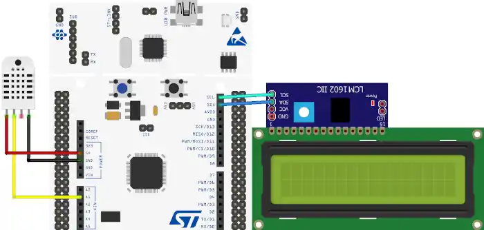
Since the DHT22 only uses 1 wire to communicate to the MCU, I have connected the Signal pin from the DHT22 to the pin PA1 of the MCU. The sensor is powered with 5V from the Nucleo board itself.
Note:
You might need to connect pull-up resistance to the data line or else DHT22 will not be able to pull it HIGH.
The LCD16x2 is connected via PCF8574 using the I2C. The connection with the STM32 is shown in the table below.
| PCF8574 Pin | STM32F103 Pin | Description |
|---|---|---|
| VCC | 5V | Power supply (5V) |
| GND | GND | Ground |
| SDA | PB7 | I²C Data line |
| SCL | PB6 | I²C Clock line |
STM32CubeMX Configuration
Clock Configuration
Below is the image showing the clock configuration for this project.
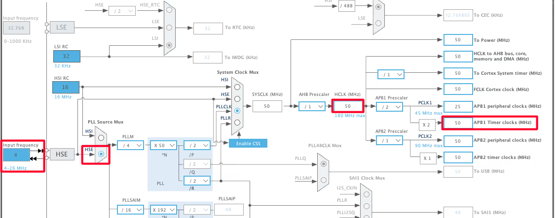
The system is clocked from the external 8MHz crystal and the HCLK is set to 50MHz.
Note that the APB1 Timer clock is also at 50MHz. This is important because we will use the TIM6 to generate the delays in microseconds and the TIM6 is connected to the APB1 bus.
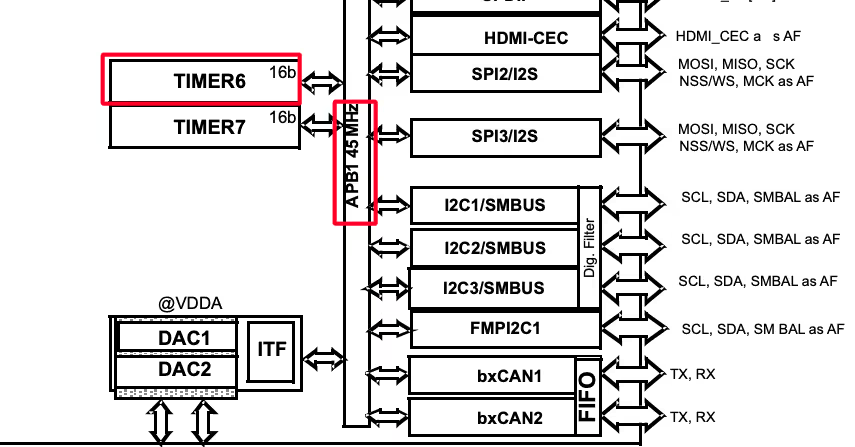
Timer Configuration
Below is the image showing the configuration of the TIM6.
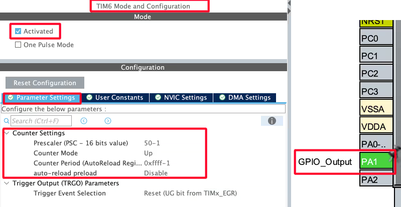
Since the APB1 Timer clock is at 50MHz, we will use the prescaler of 50 to bring the TIM6 clock to 1 MHz. This is already explained in the tutorial which explains how to generate the delays in microseconds.
The pin PA1 is set as output, this is where the DHT22 data pin is connected to.
I2C Configuration for LCD
I am using the LCD16x2 to display the Temperature and Humidity data. The LCD is connected using the PCF8574 I2C extender. Below is the image showing the I2C configuration.
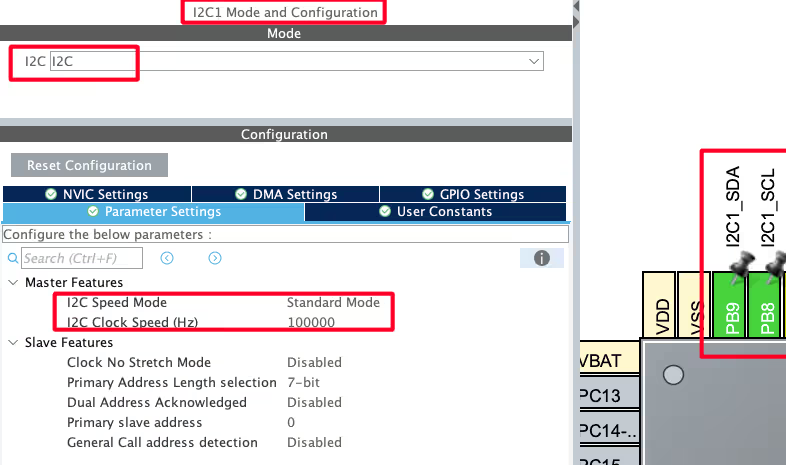
I am using the I2C1 to connect the LCD. The I2C is configured in the standard mode with the clock speed set to 100KHz. The pins PB8 and PB9 are configured as the SCL and SDA pins.
We have already covered how to Interface the LCD via I2C with STM32. You can check out the tutorial for more details.
HAL-Based Code for DHT22 Communication
Initialization
As explained in the Initialization section, below is the code for the same.
void DHT22_Start (void)
{
	Set_Pin_Output(DHT22_PORT, DHT22_PIN); // set the pin as output
	HAL_GPIO_WritePin (DHT22_PORT, DHT22_PIN, 0);   // pull the pin low
	HAL_Delay(1200);   // wait for > 1ms

	HAL_GPIO_WritePin (DHT22_PORT, DHT22_PIN, 1);   // pull the pin high
	delay (20);   // wait for 30us
	Set_Pin_Input(DHT22_PORT, DHT22_PIN);   // set as input
}- Set the pin (data) as output.
- Pull the pin low and wait for > 1 ms.
- Set the pin as input for receiving the data.
Response
As explained in the Data Transmission section, the response from the DHT22 is shown below.
uint8_t DHT22_Check_Response (void)
{
	Set_Pin_Input(DHT22_PORT, DHT22_PIN);   // set as input
	uint8_t Response = 0;
	delay (40);  // wait for 40us
	if (!(HAL_GPIO_ReadPin (DHT22_PORT, DHT22_PIN))) // if the pin is low
	{
		delay (80);   // wait for 80us

		if ((HAL_GPIO_ReadPin (DHT22_PORT, DHT22_PIN))) Response = 1;  // if the pin is high, response is ok
		else Response = -1;
	}

	while ((HAL_GPIO_ReadPin (DHT22_PORT, DHT22_PIN)));   // wait for the pin to go low
	return Response;
}- Wait for 40 us.
- Check if the pin is low, than wait for 80 us. This will totally be a delay of 120 us and the pin should be high now.
- Check if the pin is high. If it is, then the response is OK.
Read Data
Below is the code to read the data from the sensor.
uint8_t DHT22_Read (void)
{
	uint8_t i,j;
	for (j=0;j<8;j++)
	{
		while (!(HAL_GPIO_ReadPin (DHT22_PORT, DHT22_PIN)));   // wait for the pin to go high
		delay (40);   // wait for 40 us

		if (!(HAL_GPIO_ReadPin (DHT22_PORT, DHT22_PIN)))   // if the pin is low
		{
			i&= ~(1<<(7-j));   // write 0
		}
		else i|= (1<<(7-j));  // if the pin is high, write 1
		while ((HAL_GPIO_ReadPin (DHT22_PORT, DHT22_PIN)));  // wait for the pin to go low
	}

	return i;
}- Wait for the pin to go high.
- Wait for 40 us. This is because the length of “0” bit is 26-28 us and if the pin is high after 40 us, it indicates that the bit is “1”.
- Write the respective values to the variable.
The delay function used in the code above is actually the delay in microseconds. We have already covered it another tutorial and below is the function for the same.
void delay (uint16_t time)
{
	/* change your code here for the delay in microseconds */
	__HAL_TIM_SET_COUNTER(&htim6, 0);
	while ((__HAL_TIM_GET_COUNTER(&htim6))<time);
}The main function
int main()
{
  .....
  HAL_TIM_Base_Start(&htim6);  // for us Delay
  lcd_init();
  lcd_send_string("INITIALISING>>>>");
  HAL_Delay(2000);
  lcd_clear ();
  while (1)
  {
      DHT22_Start();
      Presence = DHT22_Check_Response();
      Rh_byte1 = DHT22_Read ();
      Rh_byte2 = DHT22_Read ();
      Temp_byte1 = DHT22_Read ();
      Temp_byte2 = DHT22_Read ();
      SUM = DHT22_Read();

      TEMP = ((Temp_byte1<<8)|Temp_byte2);
      RH = ((Rh_byte1<<8)|Rh_byte2);

      Temperature = (float) (TEMP/10.0);
      Humidity = (float) (RH/10.0);

      HAL_Delay(2000);

      Display_Temp(Temperature);
      Display_Rh(Humidity);
  }
}- We will first send the START condition an then check for the Presence.
- The read the 40 bit data in sequence and store it in the 5 bytes.
- Then combine the Temperature data together and Humidity data together.
- To get the actual data in °C and %Rh, we need to divide the Temp and Rh data by 10.
- Finally Display the data on the LCD.
Since we are also displaying the data on the LCD, the LCD is initialized in the main function itself. We have already covered how to use the LCD1602 via I2C to display strings, numbers, floats etc. Below are the functions for displaying the data on the LCD.
void Display_Temp (float Temp)
{
	char str[20] = {0};
	lcd_put_cur(0, 0);
	sprintf (str, "TEMP:- %.2f ", Temp);
	lcd_send_string(str);
	lcd_send_data('C');
}
void Display_Rh (float Rh)
{
char str[20] = {0};
lcd_put_cur(1, 0);
sprintf (str, "RH:- %.2f ", Rh);
lcd_send_string(str);
lcd_send_data('%');
}Result on the LCD1602
The image below shows the output of the sensor on the LCD1602.
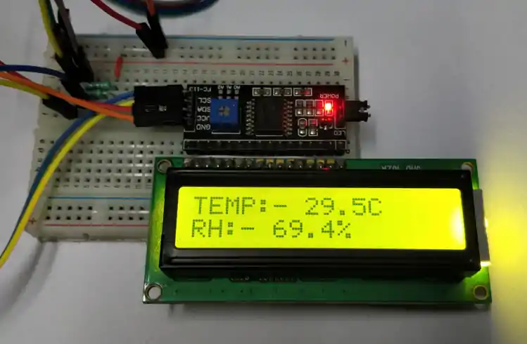
You can see the Temperature and Humidity values are displaying on the LCD.
VIDEO TUTORIAL
STM32 DHT22 Temperature & Humidity Tutorial Video
This tutorial demonstrates how to interface the DHT22 temperature and humidity sensor with an STM32 microcontroller using CubeMX and HAL. You’ll see how the DHT22 communication works, how to generate microsecond delays using a timer, send the start signal, read the 40-bit data, and extract temperature and humidity values. A complete video walkthrough is included to show the timing-critical communication and data reading process in real time. Follow the written guide along with the video for a clear understanding of the implementation.
Watch the VideoConclusion
In this tutorial, we successfully interfaced the DHT22 temperature and humidity sensor with an STM32 microcontroller using STM32CubeIDE and HAL libraries. We began by configuring a hardware timer to generate accurate microsecond delays, essential for communicating with the sensor. After sending the required start signal, we captured and decoded the 40-bit data stream sent by the DHT22. The extracted values for temperature and humidity were then verified using a checksum to ensure accuracy.
You can check out interfacing similar sensors like DHT11 sensor with STM32 and DS18B20 sensor with STM32.
Checkout More STM32 Sensors Tutorials
How to interface HCSR04 sensor with STM32
Interface BMP180 with STM32
How to Interface SHT21 Sensor with STM32 using I2C (Step-by-Step with Code and Circuit Diagram)
Interfacing ADXL345 Accelerometer with STM32 via I2C
GP2Y0A41SK0F STM32 ADC Distance Measurement Guide

Multiple DS18B20 sensors using UART
Interface AHT20 Sensor with STM32 Using I2C
STM32 DHT22 Project Download
STM32 DHT22 FAQs


Hi sir / ma’am
I trust you are well
I’m running a simulation in proteus using the STM32F401RE, DHT22 and LM016L LCD. I used the unified dht11&dht22 library provided.
When I run the simulation, the LCD initially displays the dht22 values accurately. But when I vary the value of temperature and/or the value of humidity, the new values are not being updated on the LCD. It seems like the infinite while loop in STM32CubeIDE breaks after the 1st iteration.
I even made use of uUSART communication by and added a virtual terminal (in proteus) to check if it was my LCD code the source of the problem.
The dht22 values are only displayed once on both LCD and VIRTUAL TERMINAL.
I’m looking forward to hearing from you and any assistance will be much appreciated.
Regards,
Joseph
please help me , i used an stm32 nucleo F439ZI with dht22 (AM2302).
clock config : clock freq = 180MHZ, prescale = 179 , counter period = 0xffff .
result of debugging : Error: check_response
Checksum error: SUM = 43, checksum = 389
#include “main.h”
#include “stdio.h”
/* Private variables ———————————————————*/
TIM_HandleTypeDef htim6;
/* Private function prototypes ———————————————–*/
void SystemClock_Config(void);
static void MX_GPIO_Init(void);
static void MX_TIM6_Init(void);
int _write(int file, char *ptr, int len) {
int i;
for (i = 0; i < len; i++) {
ITM_SendChar((*ptr++));
}
return len;
}
void delay_us(uint16_t us)
{
__HAL_TIM_SET_COUNTER(&htim6, 0); // Set the counter value to 0
HAL_TIM_Base_Start(&htim6); // Start the timer
while (__HAL_TIM_GET_COUNTER(&htim6) 1ms
HAL_GPIO_WritePin(DHT22_PORT, DHT22_PIN, GPIO_PIN_SET); // pull the pin high
delay_us(20); // wait for 20-40us
Set_Pin_Input(DHT22_PORT, DHT22_PIN); // set as input
}
uint8_t DHT22_Check_Response(void)
{
uint8_t Response = 0;
delay_us(40); // wait for 40us
if (!(HAL_GPIO_ReadPin(DHT22_PORT, DHT22_PIN))) // if the pin is low
{
delay_us(80); // wait for 80us
if (HAL_GPIO_ReadPin(DHT22_PORT, DHT22_PIN)) Response = 1; // if the pin is high, response is ok
else Response = -1;
}
while (HAL_GPIO_ReadPin(DHT22_PORT, DHT22_PIN)); // wait for the pin to go low
return Response;
}
uint8_t DHT22_Read(void)
{
uint8_t i, j;
for (j = 0; j < 8; j++)
{
while (!(HAL_GPIO_ReadPin(DHT22_PORT, DHT22_PIN))); // wait for the pin to go high
delay_us(40); // wait for 40 us
if (!(HAL_GPIO_ReadPin(DHT22_PORT, DHT22_PIN))) // if the pin is low
{
i &= ~(1 << (7 – j)); // write 0
}
else i |= (1 << (7 – j)); // if the pin is high, write 1
while (HAL_GPIO_ReadPin(DHT22_PORT, DHT22_PIN)); // wait for the pin to go low
}
return i;
}
/* Main Function */
int main(void)
{
HAL_Init();
SystemClock_Config();
MX_GPIO_Init();
MX_TIM6_Init();
while (1)
{
DHT22_Start();
Presence = DHT22_Check_Response();
if (Presence == 1)
{
Rh_byte1 = DHT22_Read();
Rh_byte2 = DHT22_Read();
Temp_byte1 = DHT22_Read();
Temp_byte2 = DHT22_Read();
SUM = DHT22_Read();
uint16_t checksum;
checksum = Rh_byte1 + Rh_byte2 + Temp_byte1 + Temp_byte2;
if (SUM == checksum)
{
TEMP = ((Temp_byte1 << 8) | Temp_byte2);
RH = ((Rh_byte1 << 8) | Rh_byte2);
Temperature = (float)(TEMP / 10.0);
Humidity = (float)(RH / 10.0);
printf("Temperature: %.1f°C, Humidity: %.1f%%\n", Temperature, Humidity);
}
else
{
printf("Checksum error: SUM = %d, checksum = %d\n", SUM, checksum);
}
}
else
{
printf("Error: check_response\n");
}
HAL_Delay(2000); // augmenter le délai entre les lectures pour éviter les lectures erronées
}
}
/**
* @brief System Clock Configuration
* @retval None
*/
void SystemClock_Config(void)
{
RCC_OscInitTypeDef RCC_OscInitStruct = {0};
RCC_ClkInitTypeDef RCC_ClkInitStruct = {0};
/** Configure the main internal regulator output voltage
*/
__HAL_RCC_PWR_CLK_ENABLE();
__HAL_PWR_VOLTAGESCALING_CONFIG(PWR_REGULATOR_VOLTAGE_SCALE1);
/** Initializes the RCC Oscillators according to the specified parameters
* in the RCC_OscInitTypeDef structure.
*/
RCC_OscInitStruct.OscillatorType = RCC_OSCILLATORTYPE_HSE;
RCC_OscInitStruct.HSEState = RCC_HSE_ON;
RCC_OscInitStruct.PLL.PLLState = RCC_PLL_ON;
RCC_OscInitStruct.PLL.PLLSource = RCC_PLLSOURCE_HSE;
RCC_OscInitStruct.PLL.PLLM = 8;
RCC_OscInitStruct.PLL.PLLN = 360;
RCC_OscInitStruct.PLL.PLLP = RCC_PLLP_DIV2;
RCC_OscInitStruct.PLL.PLLQ = 7;
if (HAL_RCC_OscConfig(&RCC_OscInitStruct) != HAL_OK)
{
Error_Handler();
}
/** Activate the Over-Drive mode
*/
if (HAL_PWREx_EnableOverDrive() != HAL_OK)
{
Error_Handler();
}
/** Initializes the CPU, AHB and APB buses clocks
*/
RCC_ClkInitStruct.ClockType = RCC_CLOCKTYPE_HCLK|RCC_CLOCKTYPE_SYSCLK
|RCC_CLOCKTYPE_PCLK1|RCC_CLOCKTYPE_PCLK2;
RCC_ClkInitStruct.SYSCLKSource = RCC_SYSCLKSOURCE_PLLCLK;
RCC_ClkInitStruct.AHBCLKDivider = RCC_SYSCLK_DIV1;
RCC_ClkInitStruct.APB1CLKDivider = RCC_HCLK_DIV4;
RCC_ClkInitStruct.APB2CLKDivider = RCC_HCLK_DIV2;
if (HAL_RCC_ClockConfig(&RCC_ClkInitStruct, FLASH_LATENCY_5) != HAL_OK)
{
Error_Handler();
}
}
/**
* @brief TIM6 Initialization Function
* @param None
* @retval None
*/
static void MX_TIM6_Init(void)
{
/* USER CODE BEGIN TIM6_Init 0 */
/* USER CODE END TIM6_Init 0 */
TIM_MasterConfigTypeDef sMasterConfig = {0};
/* USER CODE BEGIN TIM6_Init 1 */
/* USER CODE END TIM6_Init 1 */
htim6.Instance = TIM6;
htim6.Init.Prescaler = 179;
htim6.Init.CounterMode = TIM_COUNTERMODE_UP;
htim6.Init.Period = 0xffff;
htim6.Init.AutoReloadPreload = TIM_AUTORELOAD_PRELOAD_DISABLE;
if (HAL_TIM_Base_Init(&htim6) != HAL_OK)
{
Error_Handler();
}
sMasterConfig.MasterOutputTrigger = TIM_TRGO_RESET;
sMasterConfig.MasterSlaveMode = TIM_MASTERSLAVEMODE_DISABLE;
if (HAL_TIMEx_MasterConfigSynchronization(&htim6, &sMasterConfig) != HAL_OK)
{
Error_Handler();
}
/* USER CODE BEGIN TIM6_Init 2 */
/* USER CODE END TIM6_Init 2 */
}
/**
* @brief GPIO Initialization Function
* @param None
* @retval None
*/
static void MX_GPIO_Init(void)
{
GPIO_InitTypeDef GPIO_InitStruct = {0};
/* USER CODE BEGIN MX_GPIO_Init_1 */
/* USER CODE END MX_GPIO_Init_1 */
/* GPIO Ports Clock Enable */
__HAL_RCC_GPIOH_CLK_ENABLE();
__HAL_RCC_GPIOA_CLK_ENABLE();
__HAL_RCC_GPIOB_CLK_ENABLE();
/*Configure GPIO pin Output Level */
HAL_GPIO_WritePin(GPIOA, GPIO_PIN_5, GPIO_PIN_RESET);
/*Configure GPIO pin : PA5 */
GPIO_InitStruct.Pin = GPIO_PIN_5;
GPIO_InitStruct.Mode = GPIO_MODE_OUTPUT_PP;
GPIO_InitStruct.Pull = GPIO_NOPULL;
GPIO_InitStruct.Speed = GPIO_SPEED_FREQ_LOW;
HAL_GPIO_Init(GPIOA, &GPIO_InitStruct);
/* USER CODE BEGIN MX_GPIO_Init_2 */
/* USER CODE END MX_GPIO_Init_2 */
}
Hey man,
You got small bug here in the initialization code (just here on the website, source code in zip file is OK thought).
HAL_Delay(1200); // wait for > 1ms
should be
delay (1200); // wait for > 1ms
Checksum requires fix in the function DHT_GetData below as it is failing.
if (SUM == ( (Rh_byte1 + Rh_byte2 + Temp_byte1 + Temp_byte2) & 0x00FF) ) { #if defined(TYPE_DHT11) DHT_Data->Temperature = Temp_byte1; DHT_Data->Humidity = Rh_byte1; #endif #if defined(TYPE_DHT22) DHT_Data->Temperature = ( ((Temp_byte1 << 8) | Temp_byte2) * 0.1f); DHT_Data->Humidity = ( ((Rh_byte1 << 8) | Rh_byte2) * 0.1f); #endif }Hello,
Where can i found i2c-led.h and .c files?
check the src and inc folders..
I’ve practiced everything you’ve told us. But, while ((HAL_GPIO_ReadPin (GPIOA, GPIO_PIN_1))); // wait for the pin to go low
in this line, waiting forever, I can not go to next step. What could be the reason ?
The line of code I’m talking about in response function
I have the same problem…..
did you solve the problem
I managed to solve it with the admin. My problem was because i didn’t use 5k ohms pull up and because my stm32 f303k8 had 8MHz system clock. After using internal pull up and setting system clock to 64MHz it worked like a charm.
Unfortunately it did not solve this problem for me. Did anyone solve this problem in another way?
The same problem here… Still no solution?
i created new project and solved this problem. But i did not understand how problem is solved 🙂
i think problem is lcd_init() function. when i added lcd_init function in main funcion, dht22 is not working.
Hi, why you used separate delay function instead of HAL Delay? Any specific reason?
HAL_Delay have the minimum delay of 1 ms on the other hand DHT11 and 22 needs the delays in microseconds. That’s why I used DWT
Thanks for the clarification!
Hi! Thank you for your tuto! For the right checksum you shound do:
if (sum == ((Rh_byte1+Rh_byte2+Temp_byte1+Temp_byte2) & 0xFF))
Best regards
In line No. 78 if ((HAL_GPIO_ReadPin (GPIOA, GPIO_PIN_1))) check = 1;
Variable “check” is not used anywhrere. Could you explain Why the “check” need?
I personally used “check” for debugging purposes and forgot to remove it.
Thanks for your reply!!
can you tell how to interface ppd42 with stm32
hi please run remote codelearn 433mhz with stm32f103 please help me thanks
hello thanks for the code, i want to read values from dht22 but without using an LCD how could to modify your code to be useful in my case
just use the following code
DHT22_start ();
check_response ();
Rh_byte1 = read_data ();
Rh_byte2 = read_data ();
Temp_byte1 = read_data ();
Temp_byte2 = read_data ();
sum = read_data();
//if (sum == (Rh_byte1+Rh_byte2+Temp_byte1+Temp_byte2))
{
TEMP = ((Temp_byte1<<8)|Temp_byte2); RH = ((Rh_byte1<<8)|Rh_byte2); } No LCD related functions... that's it
thank u, i run it and it works
is it same and works for dht11 module?
DHT11 have a little different timing requirements..
I’ll post a tutorial about it soon
Hello, I just followed your youtube video here.
This code is different with another I2C code,
First your codes on this project are:
void lcd_send_cmd (char cmd)
{
char data_u, data_l;
uint8_t data_t[4];
data_u = cmd&0xf0;
data_l = (cmd<<4)&0xf0;
data_t[0] = data_u|0x04; //en=1, rs=0
data_t[1] = data_u; //en=0, rs=0
data_t[2] = data_l|0x04; //en=1, rs=0
data_t[3] = data_l; //en=0, rs=0
HAL_I2C_Master_Transmit (&hi2c1, 0x4E,(uint8_t *) data_t, 4, 100);
}
void lcd_send_data (char data)
{
char data_u, data_l;
uint8_t data_t[4];
data_u = data&0xf0;
data_l = (data<<4)&0xf0;
data_t[0] = data_u|0x05; //en=1, rs=0
data_t[1] = data_u|0x01; //en=0, rs=0
data_t[2] = data_l|0x05; //en=1, rs=0
data_t[3] = data_l|0x01; //en=0, rs=0
HAL_I2C_Master_Transmit (&hi2c1, 0x4E,(uint8_t *) data_t, 4, 100);
}
But in another project, the lcd_send_cmd and lcd_send_data used different numbers for the data_t[ ] calculation. Why and which one is correct?
void lcd_send_cmd (char cmd)
{
char data_u, data_l;
uint8_t data_t[4];
data_u = (cmd&0xf0);
data_l = ((cmd<<4)&0xf0);
data_t[0] = data_u|0x0C; //en=1, rs=0
data_t[1] = data_u|0x08; //en=0, rs=0
data_t[2] = data_l|0x0C; //en=1, rs=0
data_t[3] = data_l|0x08; //en=0, rs=0
HAL_I2C_Master_Transmit (&hi2c1, SLAVE_ADDRESS_LCD,(uint8_t *) data_t, 4, 100);
}
void lcd_send_data (char data)
{
char data_u, data_l;
uint8_t data_t[4];
data_u = (data&0xf0);
data_l = ((data<<4)&0xf0);
data_t[0] = data_u|0x0D; //en=1, rs=0
data_t[1] = data_u|0x09; //en=0, rs=0
data_t[2] = data_l|0x0D; //en=1, rs=0
data_t[3] = data_l|0x09; //en=0, rs=0
HAL_I2C_Master_Transmit (&hi2c1, SLAVE_ADDRESS_LCD,(uint8_t *) data_t, 4, 100);
}
The down one is a fix for lcd backlight so I recommend you use that.
Thank you for your response.
I have another question:
What commands should I send to turn on/off the backlight? I know P3 is the backlight control pin.
I just can’t figure out a way to change only one bit of the register.
I figured it out myself. Need to read the register first then change P3 bit and write it back.
Do I need to change the Master Transmit address from 0x4E to whatevery my I2C is putting out? For Arduino I needed to use a scanner and check to see what it was and change that over before transmitting? Just wondering because I used everything here for my STM32F4 and it’s not working…thanks.
0x4E is the address of the slave device PCF8574. If you are using any other variant, you need to change the address.
where is dwt_stm32_delay.h/dwt_stm32_delay.c please !
Sorry for that. I uploaded the wrong one.
You can download NOW
Hi, Where are the “dwt_stm32_delay.h/dwt_stm32_delay.c ” and i2c files… Please I need them asap. Many thanks.
Download the code.. They are in src and inc folders