STM32 Communication using HC-05
In this tutorial we will cover how to setup the HC-05 modules in the master and slave mode. Then use these modules to communicate between the two STM32 controllers.
The HC-05 module is an easy to use Bluetooth SPP (Serial Port Protocol) module, designed for transparent wireless serial connection setup. The HC-05 supports both the master and the slave modes. It also supports UART interface with programmable baud rates ranging from 9600 to 460800.
We will first setup the modules in their respective modes. This can be done by first connecting the module in the AT command mode. Let’s start by configuring the Module1 in the slave mode.
VIDEO TUTORIAL
You can check the video to see the complete explanation and working of this project.
Module1 in the slave mode
To send the AT commands to the module, we first need to connect the module in the AT mode. Below is the picture showing the connection of the module.
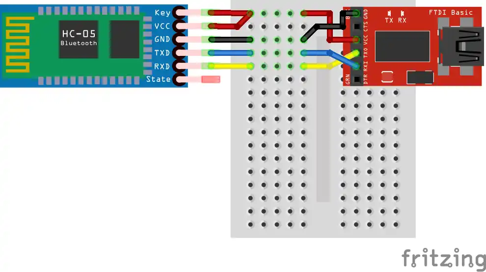
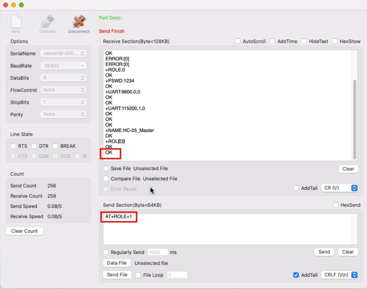
We will first connect the module directly to the FT232 USB to TTL converter, so that we can send the commands directly from the computer to the module.
The EN/Key pin must be connected to the VCC to put the module in the AT mode. Once all the connections are established, power up the module. The blinking of the LED on the module confirms if it is in the AT mode or not. This is shown below.

The LED remains on for 2 seconds, and off for another 2 seconds. This confirms that the module has entered the AT mode.
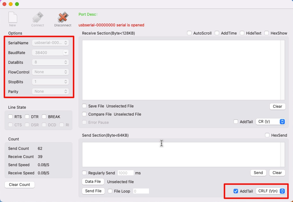
Now open a serial monitor software to send the AT commands to the module. The default baud rate in the AT mode is 38400.
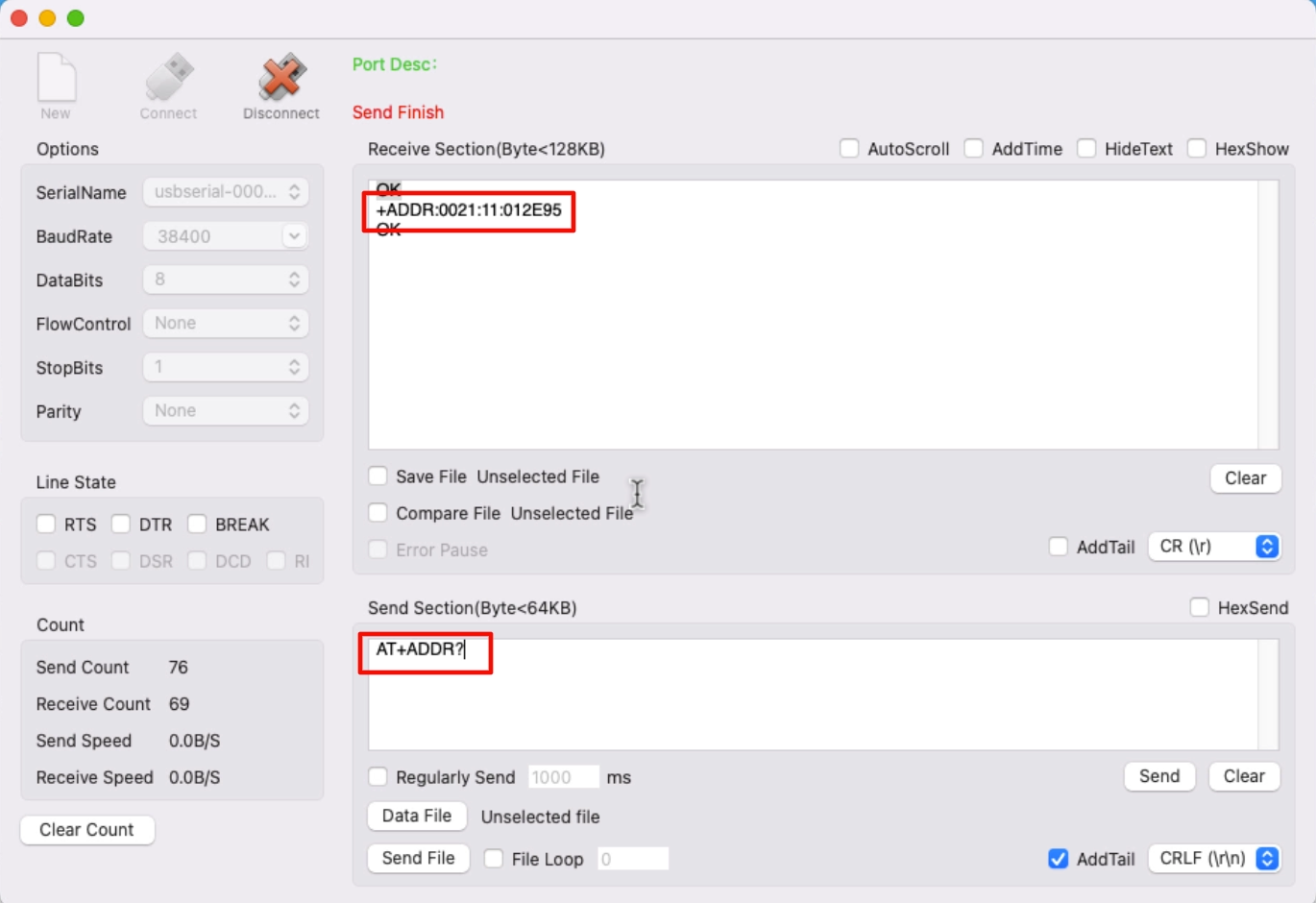
By default the module is already in the slave mode with the pairing pin as “1234“. We will just get the Address of this module, so that the master can pair with it.
Also set the baud rate of the module to 115200 with 1 stop bit and no parity. AT+UART command is used to do so.
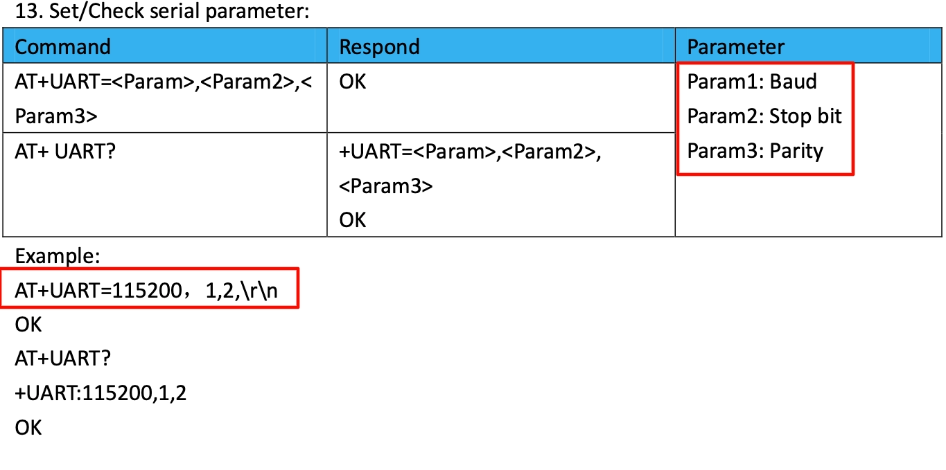
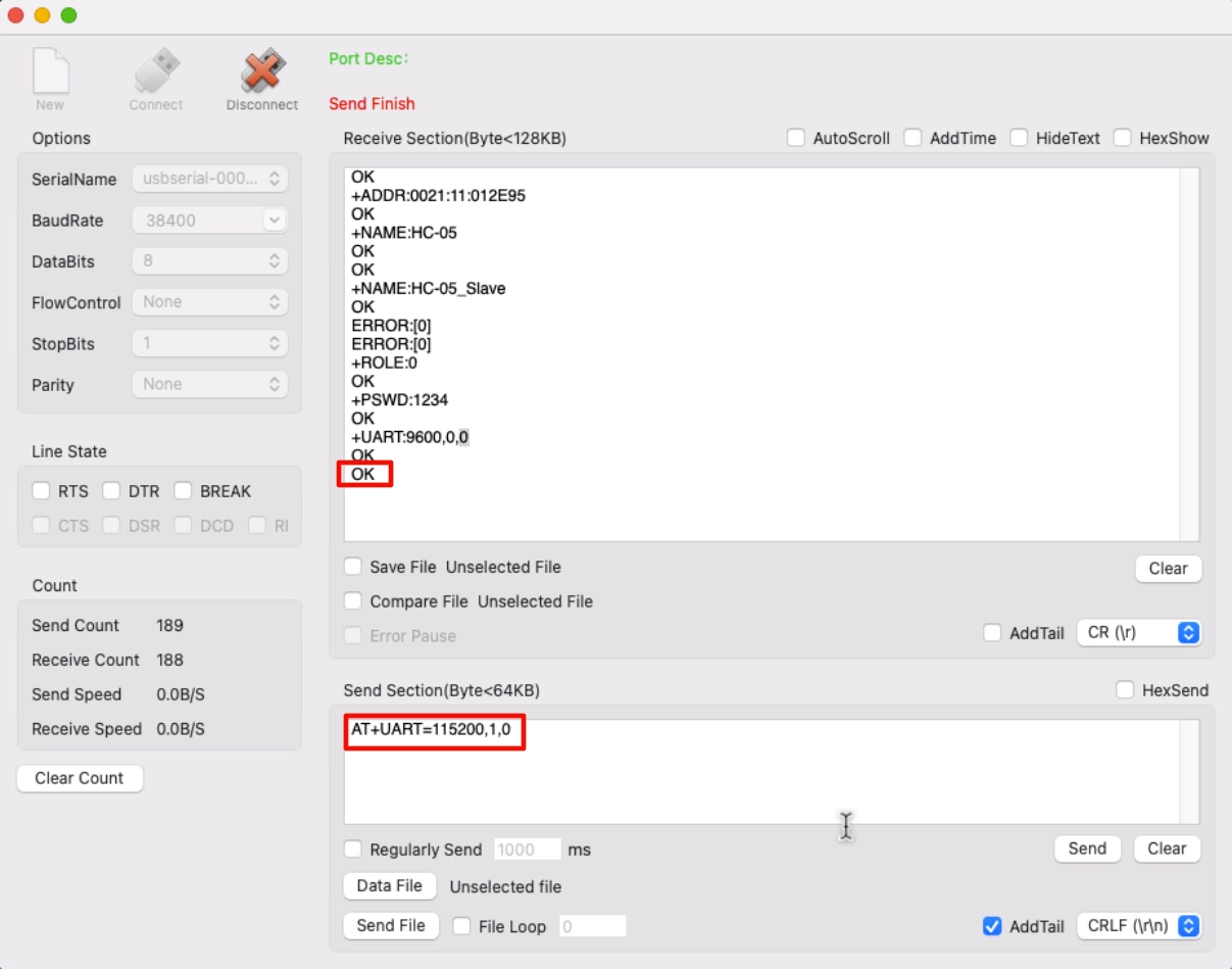
We will use the same baud rate for everything in this entire project.
We will keep the rest of the settings to the default. You can watch the video for more detailed explanation on the commands.
Module2 in the Master mode
Module 2 connects in the similar way to the FT232 as we connect the Module1. Once it goes into the AT mode, we will send commands to first put the module in the master mode, and then pair with the slave.
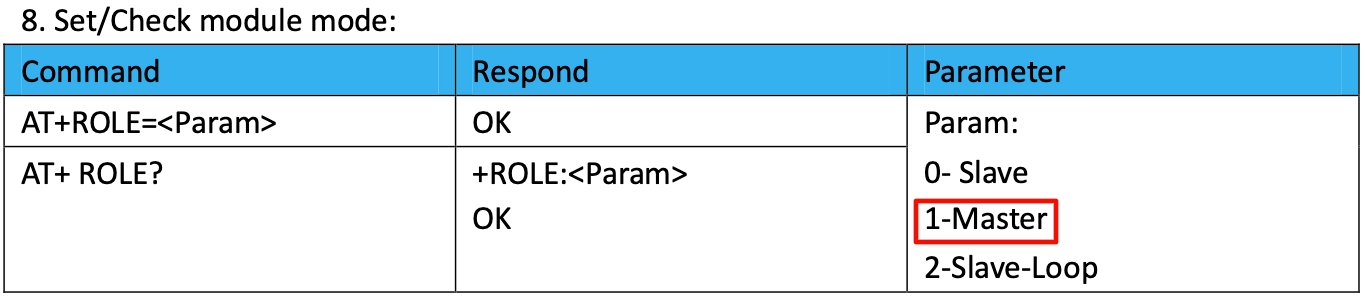
The baud rate settings for Module2 will be similar as we did for the Module1. Other than that we will first put the module in Master mode by issuing the AT+ROLE command.
After setting the Module in the Master mode, we will Bind the Module to the slave Address.
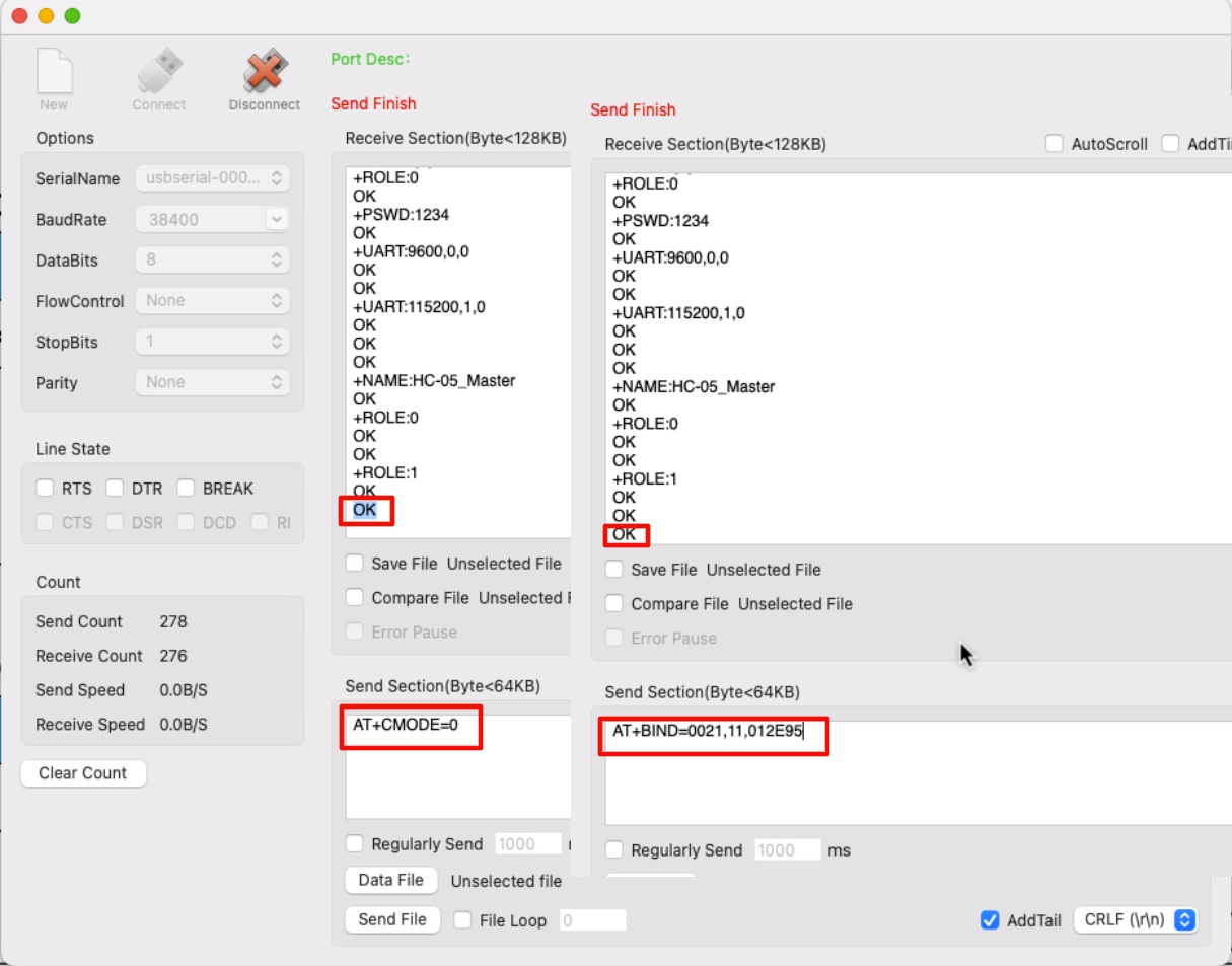
The AT+CMODE=0 command allows the Master to pair with a fixed Address Slave. Then AT+BIND command is used to Bind the module to the slave. Here we use the Address of the Slave module, that we got in the beginning. The colons(:) in the address should be replaced with the comma(,).
The pairing pin is same as the slave “1234”. This is must if you want the master to automatically pair with the slave.
Once the modules powers up, the Master will be connected to the Slave. When paired, the LED blinks twice every 5 seconds. This confirms that the modules have paired with each other.

We will now connect the modules to the STM32 controllers using UART. The controllers will be connected to the computer using another UART.
The data sent from one computer (1) to the STM32 (1) will transmit through HC-05 (1) to HC-05 (2), and then STM32 (2) will send this data to computer (2).
Basically both computers will be able to communicate with each other, using STM32 and the Bluetooth Modules.
F103 Connection and Code
Below is the CubeMX setup for F103C8.
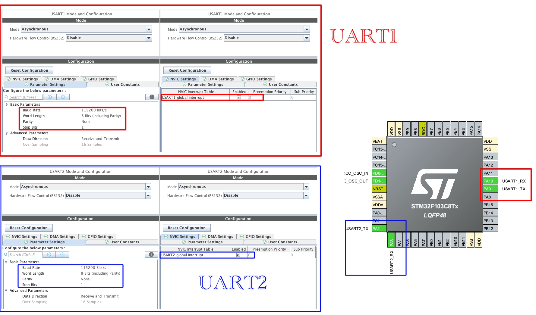
We will use 2 UARTs. One will be connected to the module and another to the Computer. The configuration for both the UARTs is same as what we configured the Modules with, i.e. The Baud rate of 115200 with 1 stop bit and no parity.
The connection between the module and the STM32, and between STM32 and FT232 is shown in the picture below.
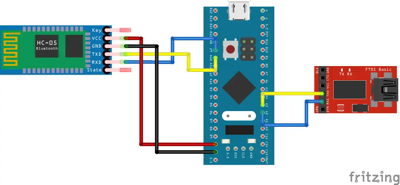
I used UART1 to connect to the Module and UART2 to connect to the FT232, which is then connected to the computer. The connections in UART is always in cross, connecting RX to TX and TX to RX.
The code
In the main function, we will set the UARTs in the Receive to IDLE interrupt mode.
  HAL_UARTEx_ReceiveToIdle_IT(&huart2, Data, 64);
HAL_UARTEx_ReceiveToIdle_IT(&huart4, Data, 64);For both the UARTs the received data will be stored in the Data buffer. Once all the 64 bytes are received, or if an IDLE line is dented before that, an interrupt will be triggered and the RX Event callback is called.
void HAL_UARTEx_RxEventCallback(UART_HandleTypeDef *huart, uint16_t Size)
{
if (huart->Instance==USART2)
{
HAL_UART_Transmit(&huart4, Data, Size, 1000);
}
else if (huart->Instance==UART4)
{
HAL_UART_Transmit(&huart2, Data, Size, 1000);
}
HAL_UARTEx_ReceiveToIdle_IT(huart, Data, 64);
}Inside the callback, we will check if the interrupt is triggered by the USART1. If it is, then transmit the received data to the UART2. The Size parameter contains the actual number of bytes received by the respective UART.
Similarly, if the interrupt is triggered by the USART2, we will transmit the received data to the UART1.
HAL disables the interrupt after each call, so in the end we will call the Receive to IDLE interrupt again.
F446 Connection and code
The F446 is connected in the similar ways as the F103. Below is the cubeMX setup.
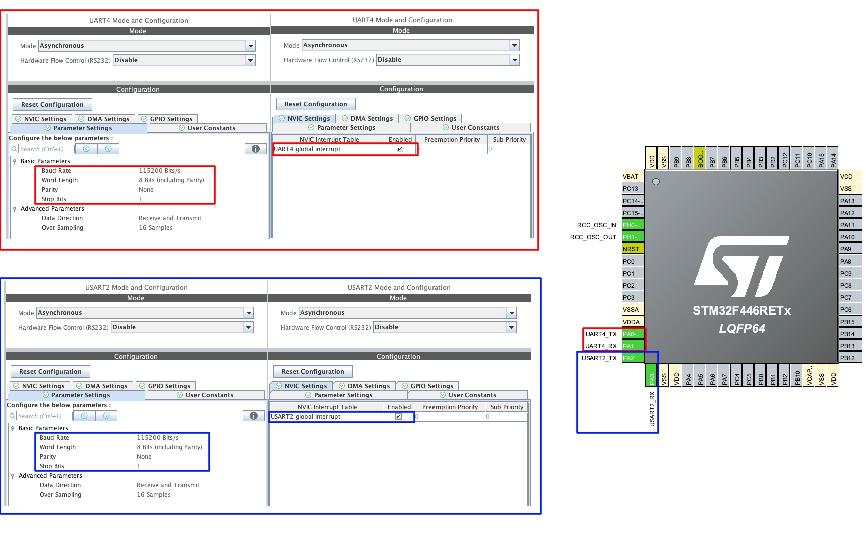
Here I am using the UART4 to connect to the module and UART2 will be connected to the computer. The configuration for the UARTs is same as what we did for the Modules.
The connection between the module and the F446 is shown below.
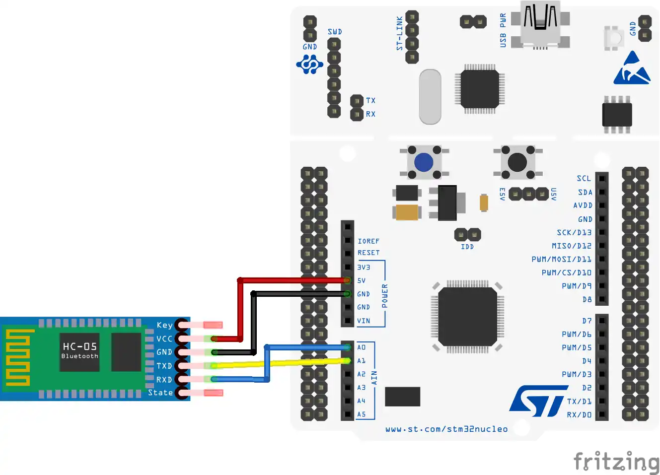
As I said the UART4 is used to connect to the module. The connections is in the cross, connecting RX to the TX and TX to the RX.
The UART2 routes the data through the ST link, so it doesn’t need any additional hardware for the connection.
The code
The code is exactly the same that we wrote for the F103. In the main function, we will set the UARTs in the Receive to IDLE interrupt mode.
  HAL_UARTEx_ReceiveToIdle_IT(&huart2, Data, 64);
  HAL_UARTEx_ReceiveToIdle_IT(&huart4, Data, 64);
For both the UARTs the received data will be stored in the Data buffer. Once all the 64 bytes are received, or if an IDLE line is dented before that, an interrupt will be triggered and the RX Event callback is called.
void HAL_UARTEx_RxEventCallback(UART_HandleTypeDef *huart, uint16_t Size)
{
	if (huart->Instance==USART2)
	{
		HAL_UART_Transmit(&huart4, Data, Size, 1000);
	}

	else if (huart->Instance==UART4)
	{
		HAL_UART_Transmit(&huart2, Data, Size, 1000);
	}

	HAL_UARTEx_ReceiveToIdle_IT(huart, Data, 64);
}
Inside the callback, we will check if the interrupt is triggered by the USART2. If it is, then transmit the received data to the UART4. The Size parameter contains the actual number of bytes received by the respective UART.
Similarly, if the interrupt is triggered by the UART4, we will transmit the received data to the UART2.
Note that UART4 is not USART4.
Result
Below is the image showing the data sent and received by Both the computers.
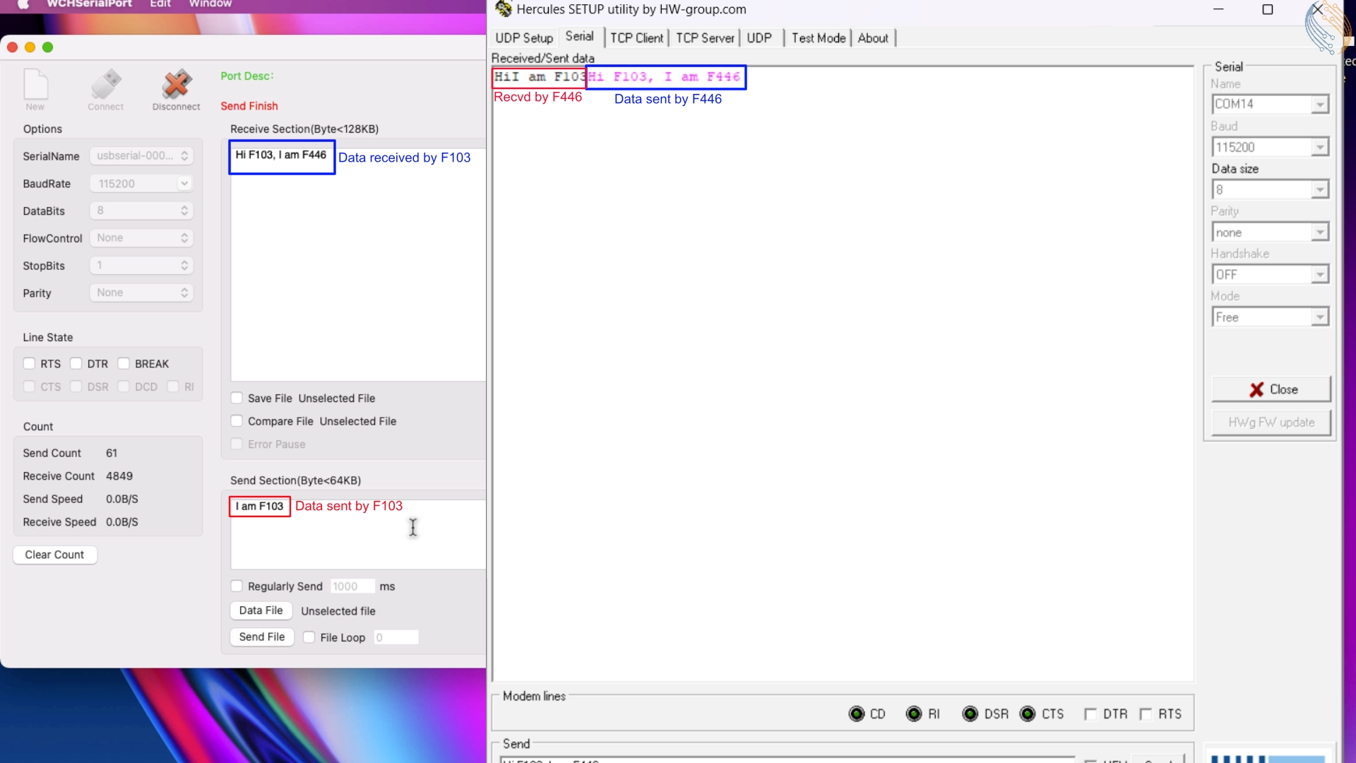
As you can see, the data sent by the F103 was received by the F446. Similarly, the data sent by the F446 was received by the F103. So the communications is working fine both the ways. For more detailed working, check out the video below.


thanks for the reference code and the wonderful explanation.
This is my arduino code .
If there is some problem with the code please let me know. Thanks
#include
SoftwareSerial btSerial(15,14);
void setup() {
// put your setup code here, to run once:
Serial.begin(115200);
//Serial.println(“AT commands: “);
btSerial.begin(115200);
}
void loop() {
// put your main code here, to run repeatedly:
if(Serial.available())
{
btSerial.write(Serial.read());
//Serial.println(Serial.read());
}
if(btSerial.available())
Serial.write(btSerial.read());
//Serial.println(btSerial.read());
}
i am using STM32 F103RB, Arduino Mega and two Hc-05 modules. i am using the same code for the stm 32 that you wrote. And as USART 2 is already configure for communicating with computer so i configure USART1 for the hc-05. In total there are 2 USART , one for hc-05 and the other for computer. In your the computer is connected with USART4 so you write huart->Instance==UART4 , and when i write this line as huart->Instance==UART2 , this gives me error. And the error is UART2 is undefined. And when i write UART2 then the code works but is doesent send the data to arduino. the arduino mega is sending data through serial monitor to hc-05 slave and the master is then sending it to the stm32 and it is displayed on the serial monitor (hercules by utility) and when i send data from stm to arduino it doesent receive on the arduino . so whats the problem
Can you please help me with this problem
“and when i write this line as huart->Instance==UART2 , this gives me error. And the error is UART2 is undefined. And when i write UART2 then the code works” ? What are you trying to say here ?