
Home ▸ STM32 Tutorials ▸
Updated On: September 14, 2025
I2C SLAVE Sends the Data to the Master
This is the 6th tutorial in the STM32 I2C Slave series. This tutorial will cover how the Slave responds to the Read request from the master and sends the required number of bytes.
The I2C REGISTERS defined in the previous tutorial will act as the memory registers. The master will request the data from these registers, and the slave will respond by sending the respective data.
uint8_t I2C_REGISTERS[10] = {0,0,0,0,0,0,0,0,0,0};The master can write a byte to a single register or multiple bytes starting from a particular register.
We will continue this tutorial from where we left in the PART5 of this series. Most of the code will remain exactly the same as the PART5 and we will just add the Transmission of data into it.
VIDEO TUTORIAL
You can check the video to see the complete explanation and working of this project.
CubeMX Setup
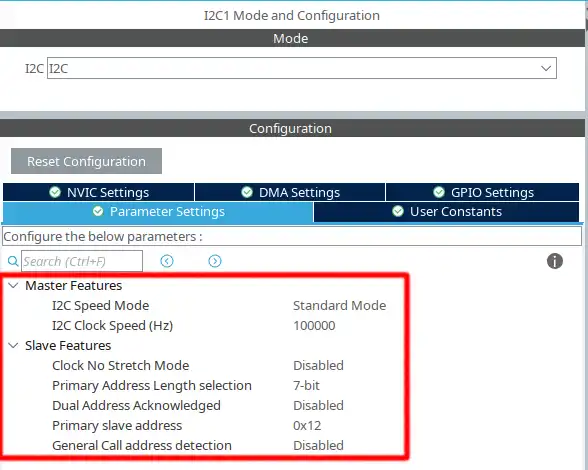
Above shown is the configuration for the I2C1
- The mode is set as standard mode with the clock speed of 100000 Hz
- The
Clock No Stretch Modeis disabled, that means the Clock stretching is enabled. - The Primary slave address length is 7 bit and the address for the device is set to 0x12 (7 bit)
- The STM32 I2C is capable of acting as 2 different slave devices with 2 different addresses, but it is disabled, and there will be only 1 slave.
- We will cover more about Clock stretching and General call address detection in the upcoming tutorials.
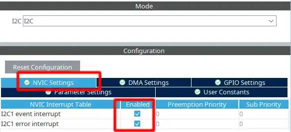
We also need to enable the Event Interrupt and Error Interrupt in the NVIC Tab
The pinout is shown below
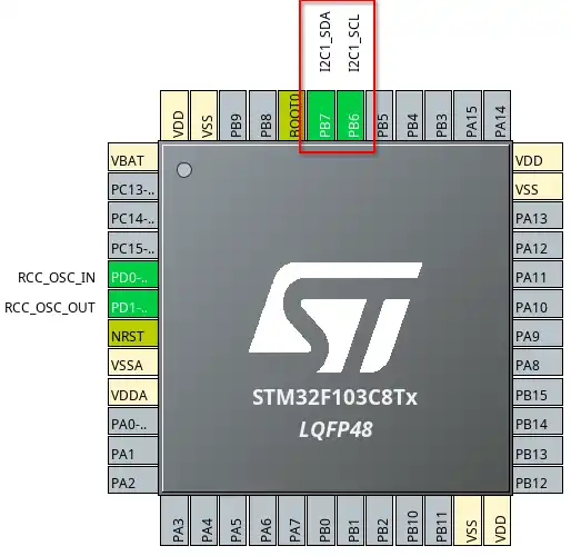
The pin PB6 is the SCL (Clock) pin and must be connectde to the SCL pin of the master. The pin PB7 is the SDA (Data) pin and must be connected to the SDA of the master. If you are connecting 2 similar MCUs, you can connect the same pins together. For eg- PB6 -> PB6 and PB7 -> PB7.
Some Insight into the CODE
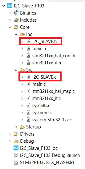
We created separate file to write the source code for the I2C Slave. We will modify these files again.
The i2c_slave.c is in the src folder and the i2c_slave.h is in the inc folder. The image is shown below.
The main function remains the same. We put the I2C in the Listen mode.
HAL_I2C_EnableListen_IT(&hi2c1);Address Callback
The changes are going to be made in the slave source file. They are as follows
uint8_t bytesTransd = 0;
uint8_t txcount = 0;
uint8_t startPosition = 0;

void HAL_I2C_AddrCallback(I2C_HandleTypeDef *hi2c, uint8_t TransferDirection, uint16_t AddrMatchCode)
{
	if (TransferDirection == I2C_DIRECTION_TRANSMIT)  // if the master wants to transmit the data
	{
		RxData[0] = 0;  // reset the RxData[0] to clear any residue address from previous call
		rxcount =0;
		HAL_I2C_Slave_Seq_Receive_IT(hi2c, RxData+rxcount, 1, I2C_FIRST_FRAME);
}The Address Callback is called when the address sent by master matches with the slave address.
- Here we will check if the Master wants to Write the data or Read it, using the variable TransferDirection.
- If the Master wants to write (Transmit) the data, we will start receiving the data.
- The RxData[0] holds the position of the START REGISTER, where the master wants to Read/Write from. So we reset this register to remove any old data left due to error.
- The variable rxcount keeps track of the buffer position, so we will reset it to 0. This way the new data will start storing from the beginning of the RxData buffer.
- The slave will receive only 1 byte in the interrupt mode, and the Option is set as I2C_FIRST_FRAME.
- THis first byte will be the Start Register address where the master wants to Read/Write from.
- The FIRST FRAME option allow to manage a sequence with start condition, and is generally used when the slave receives the fresh new byte.
Once the slave successfully receives 1 byte data, the Rx complete callback is called.
The read request by the master is generated as follows:
START -> SLAVE_ADDRESS (Write) -> REGISTER_ADDRESS -> START -> SLAVE_ADDRESS (Read) -> Receive Data
When the master writes the Register address, it gets stored in the RxData[0]. When the master sends the START followed by the Slave Adress, the Address Callback is called again. This time the transfer Direction will be set to receive and the else condition in the callback will execute.
	else
	{
		txcount = 0;
		startPosition = RxData[0];
		RxData[0] = 0;  // Reset the start register as we have already copied it
		HAL_I2C_Slave_Seq_Transmit_IT(hi2c, I2C_REGISTERS+startPosition+txcount, 1, I2C_FIRST_FRAME);
	}
}If the Transfer direction is RECEIVE, the slave need to transmit the data to the master.
- The variable txcount keeps track of the number of bytes transferred, so we will reset it to 0.
- Extract the Register Address from the RxData buffer, and store it in the variable startposition.
- Reset the RxData[0] as we have already occupied the Start Register address.
- Now the slave will Transmit only 1 byte in the interrupt mode, and the Option is set as I2C_FIRST_FRAME
- The FIRST FRAME option allow to manage a sequence with start condition, and is generally used when the slave Transmits the fresh new byte.
Once the 1 byte is transferred, the Transmit Callback is called.
Transmit Callback
void HAL_I2C_SlaveTxCpltCallback(I2C_HandleTypeDef *hi2c)
{
	txcount++;
	HAL_I2C_Slave_Seq_Transmit_IT(hi2c, I2C_REGISTERS+startPosition+txcount, 1, I2C_NEXT_FRAME);
}- Here we will increment the txcount variable to indicate that 1 new byte has been transferred. This will also update the position of the data in the I2C REGISTERS.
- Then transmit another byte with the option of the NEXT FRAME.
- I2C_NEXT_FRAME implies that the slave is Transmitting this byte and is also ready to transmit the next byte.
Since the slave has no way of knowing how many bytes the master had requested, this callback will keep running until the master sends a NACK response. This makes the Transmit callback to be called even after transferring the Last data byte. Hence the txcount variable has the value 1 higher than the actual number of data bytes transferred.
Since the master sends a NACK response while the slave was preparing to transfer the next byte, an AF (ACK Failure) error will be triggered in the slave. This will call the error callback.
Error Callback
There are generally 2 types of errors gets triggered while the master receives the data.
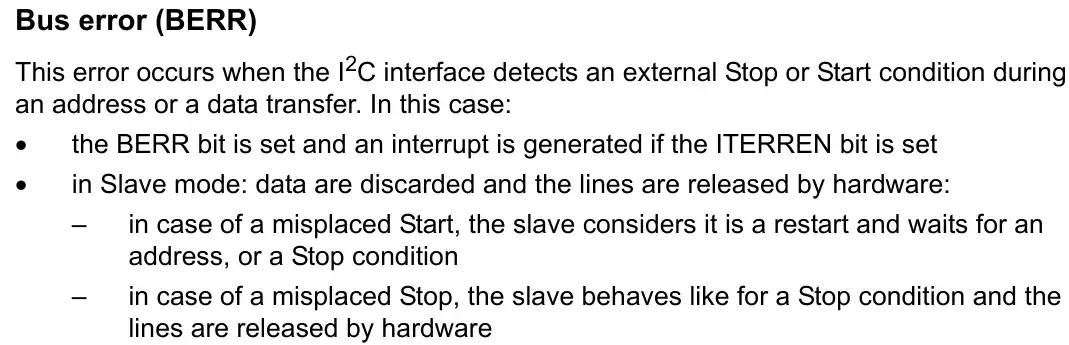
- The Bus Error (BERR) gets triggered when the slave detects a misplaced start or stop condition.
- The Acknowledgement Failure (AF) Error gets triggered when the slave receives a NACK response while sending or receiving the data.
We will first retrieve the error code to check which error ig generated.
void HAL_I2C_ErrorCallback(I2C_HandleTypeDef *hi2c)
{
uint32_t errorcode = HAL_I2C_GetError(hi2c);Now we will handle each error. Let’s start with the
Acknowledgement Failure Error
if (errorcode == 4)  // AF error
{
	if (txcount == 0)  // error is while slave is receiving
	{
		bytesRrecvd = rxcount-1;  // the first byte is the register address
		rxcount = 0;  // Reset the rxcount for the next operation
		process_data();
	}
	else // error while slave is transmitting
	{
		bytesTransd = txcount-1;  // the txcount is 1 higher than the actual data transmitted
		txcount = 0;  // Reset the txcount for the next operation
	}
}If you remember from the previous tutorial, the AF ERROR also gets triggered while receiving. This happens when the master sends the stop condition while the slave was expecting the data byte.
So we have to make a check in the error callback to make sure if the error is trigered while receiving or teransmitting the data.
- The check can be performed by checking the txcount value.
- If the txcount is 0, it means the slave never transmitted the data. And hence the error must have been caused while receiving.
- Else if the txcount is not 0, that means the slave has transferrred some data. And the error must have been caused while Transmitting.
- If the AF Error is caused while receiving the data, we will call the process data function, Just like we did in the previous tutorial.
- Before doing that we will update the bytes received and reset the rxcount, so to prepare for the new data.
- And if the AF Error is caused while transmitting, we will simply update the bytes transmitted.
- I have mentioned above that the txcount value is 1 higher than the actual number of bytes transferred, so we are reducing it by 1.
Bus Error (BERR)
The Bus Error (BERR) is triggered when the slavbe detects a misplaced start or stop condition while the data transfer is going on.
The HAL handles the bus error in the error handler function itself. The BERR part of the error handler is shown below
 /* I2C Bus error interrupt occurred ----------------------------------------*/
  if ((I2C_CHECK_FLAG(sr1itflags, I2C_FLAG_BERR) != RESET) && (I2C_CHECK_IT_SOURCE(itsources, I2C_IT_ERR) != RESET))
  {
    error |= HAL_I2C_ERROR_BERR;

    /* Clear BERR flag */
    __HAL_I2C_CLEAR_FLAG(hi2c, I2C_FLAG_BERR);

    /* Workaround: Start cannot be generated after a misplaced Stop */
    SET_BIT(hi2c->Instance->CR1, I2C_CR1_SWRST);
}Here the HAL clears the BERR Flasg and perform a software reset for the I2C by setting the bit SWRST in the CR1 Register. Below you can see the details about the SWRST bit.
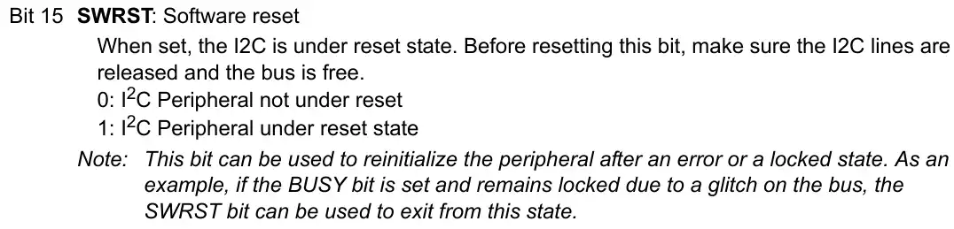
As mentioned in the reference manual, we must make sure the I2C lines are released and the bus is free before resetting this bit.
Not to make it too complicated, I am simply reinitializing the peripheral in case of the BERR error. The code is shown below.
/* BERR Error commonly occurs during the Direction switch
 * Here we the software reset bit is set by the HAL error handler
 * Before resetting this bit, we make sure the I2C lines are released and the bus is free
 * I am simply reinitializing the I2C to do so
 */
else if (errorcode == 1)  // BERR Error
{
	HAL_I2C_DeInit(hi2c);
	HAL_I2C_Init(hi2c);
	memset(RxData,'\0',RxSIZE);  // reset the Rx buffer
	rxcount =0;  // reset the count
}Here we will deinitialize and initialize the peripheral again. We will also reset any data in the buffer.
Once both the errors are handled, we will again put the peripheral in the listen mode.
	HAL_I2C_EnableListen_IT(hi2c);
}Result
Below is the image showing the commands sent by the master and the response sent by the slave.
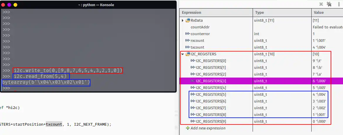
- The RED box indicates that the master writes the 10 bytes of data starting from the register 0. The data is then stored in the array I2C_REGISTERS in the slave.
- The BLUE box indicates the master requests the 4 bytes of data starting from the register 5.
- The slave sends the data stored in the 4 registers, starting from register 5.
- The data is then received by the master.
STM32 I2C Slave Tutorial Series

STM32 as I2C SLAVE || PART 2

STM32 as I2C SLAVE || PART 3

STM32 as I2C SLAVE || PART 4

STM32 as I2C SLAVE || PART 5

STM32 as I2C SLAVE || PART 7


I am trying to use this example on the STM32G031. I have python running on my PC. When I scan() I receive a response the address 19 instead of 18? I have an EEprom at 80 on the same but and it works correctly.
I’m using an STM32F042F4P6TR and encountering an issue similar to what Young described. When the master sends a NACK, the
HAL_I2C_ErrorCallback()is not triggered. I worked around this by usingHAL_I2C_ListenCpltCallback()to detect the STOP condition and then re-enabling listening withHAL_I2C_EnableListen_IT(). This allows the slave to acknowledge the address correctly on the next transaction.However, a new issue has come up: after the slave acknowledges the address, the first data byte sent by the master seems to be NACKed by the slave, and communication stalls. I’m unsure how to resolve this and would appreciate any insights or suggestions.
Thank you for the sharing of this i2c slave implementation.
I found a problem in error callback.
When i2c master writes to a slave, the AF error doesn’t happen sometimes.
I am using STM32F767.