Home ▸ STM32 Tutorials ▸ LWIP Ethernet ▸
Updated On: April 30, 2026
STM32 Ethernet Setup: Configure LWIP and Run a Ping Test
Getting Ethernet running on STM32 for the first time involves more moving parts than most peripherals — PHY address, RMII pin mapping, LWIP heap placement, and on Cortex-M7 devices, MPU cache coherency that will HardFault your board if skipped. This tutorial walks through every step so you end up with a working, ping-verified connection.
You will configure the MAC/PHY hardware in CubeMX, enable LWIP with a static IP, modify the linker script for DMA descriptor placement, and run a ping test to confirm everything is working. The tutorial covers multiple boards (Nucleo F207ZG, F7508 Discovery, H745 Discovery) and calls out where the setup differs between Cortex-M4 and Cortex-M7 devices.
This is Part 1 of the STM32 Ethernet series. You can browse the other tutorials below:
STM32 Ethernet: MAC, PHY, and How It Works
MAC and PHY Overview
The STM32 Ethernet peripheral is split into two parts that must work together. The MAC (Media Access Controller) lives inside the STM32 itself — it handles framing, addressing, and packet management. The PHY (Physical Layer) is an external chip, typically connected over RMII or MII, that handles the actual electrical signaling on the cable, link detection, and speed negotiation.
CubeMX configures the MAC side. The PHY chip (e.g. LAN8742, DP83848, LAN8720) handles the physical side. Getting the PHY address and pin mapping right in CubeMX is the single most common failure point — the connection simply won’t establish if either is wrong.
RMII vs MII
Most modern STM32 Ethernet boards use RMII (Reduced Media Independent Interface), which requires fewer pins than full MII. Check your board’s schematic to confirm which interface the PHY is wired for — configuring the wrong one in CubeMX will result in no link, even if all other settings are correct.
Why Ethernet over UART, SPI, or I2C?
Ethernet is the right choice when your STM32 project needs high data throughput, long cable runs, or connection to a LAN/router. It supports running a full TCP/IP stack (via LWIP), acting as a UDP server, hosting an HTTP interface, or connecting to MQTT brokers — none of which are practical over UART or SPI.
Ethernet is one of the most reliable and widely used communication methods in embedded systems. With STM32 microcontrollers, you can enable high-speed networking by combining the Ethernet peripheral, CubeMX configuration, and the LWIP stack. This tutorial explains how to set up Ethernet on STM32 step by step, starting from the basics of MAC and PHY to testing the connection with a ping.
STM32 Ethernet CubeMX Setup: LWIP, MPU & Flash Script
After enabling the Ethernet, you must cross check the pins configured by the CubeMX with the schematic of the board. Most of the times, the pins are configured incorrectly and it becomes one of the most popular error for the ethernet to not work.
Ethernet Peripheral Configuration
There are many types of configurations available with different MCUs. Some MCUs let you configure the memory in the CubeMX, while others don’t. Some of the Boards have the MII Type Hardware, while other have RMII Type.
Below is the picture showing different configuration available in different ST Boards.
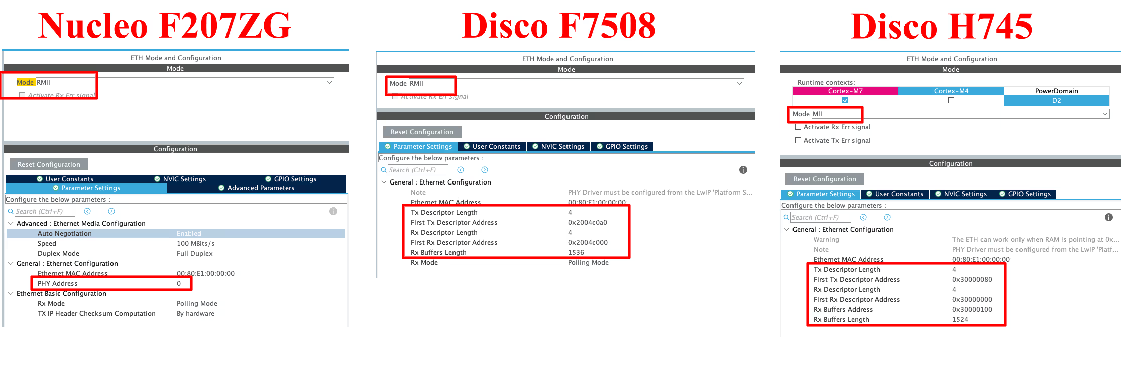
- The First board (Nucleo F207ZG) and second board (Disco F7508) uses the RMII pinout, while the third board (Disco H745) uses the MII pinout.
- On the first board we have the option to choose the PHY Address. This should be set to 0, if you are using the on board LAN Port, and it should be 1 in case of the external module.
- The 2nd and 3rd boards allow us to configure the memory addresses while the first one does not. If your board does not allow the memory configuration, you can simply skip those steps.
- The H745 discovery board is letting us configure the addresses for Tx and Rx DMA descriptors, and for the Rx Buffer as well. But the F7508 Discovery board does not let us configure the address for the Rx Buffer.
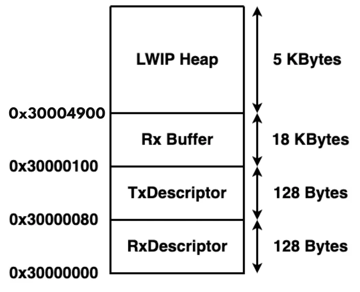
- Assuming that each DMA Descriptor takes 32 bits (MAXIMUM Possible), the RX Descriptor and Tx Descriptor have a maximum size of 128 Bytes (32×4) each.
- The Memory between them is spaced keeping this 128 bytes in mind.
- The Rx Buffer length is set to 1524 Bytes (1536 Bytes in H745 Discovery), but the number of RX buffers to be used can be defined later in the LWIP configuration. By default the cubeMX sets the number to 12 buffers. This would make the total length of Rx Buffer around 18KB.
- The memories are allocated in the SRAM region, whose properties can be modified later in the MPU.
LWIP Setup (Static IP, Heap, PHY Settings)
The LightWeight IP can be enabled in the middleware section. If the MCU does not let you enable it, make sure the cache (DCache and ICache) are enabled.
The most of the Configuration in the LWIP remains same. Except, some MCUs let us choose the address for the Heap.
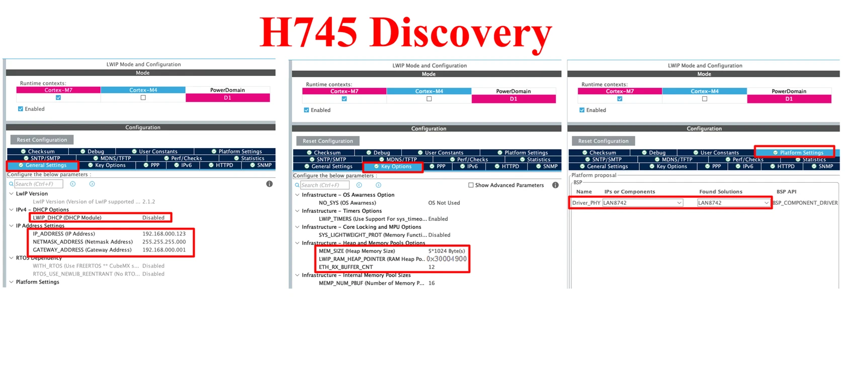
- Here we are going to disable the DHCP, and configure a static IP for our ethernet module. I have set the IP 192.168.0.123 for the board.
- In the Key Option tab, I am using 5KB memory for the Heap. The location for this heap is defined as 0x30004900.
- In the Platform Settings tab, set the PHY as LAN8742.
Note:
The LWIP heap in CubeMX is often defaulted to 0x30004000, but based on the DMA descriptor layout (RxDescriptor at 0x30000000, TxDescriptor at 0x30000080, RxBuffer at 0x30000100 spanning ~18KB), the heap should start at 0x30004900 to avoid overlapping with the Rx buffer. For small projects this may not cause immediate problems, but it will in larger ones — set it correctly from the start.
MPU Configuration for Cortex-M7 (Cache Coherency Fix)
We have the DMA Descriptors in the SRAM Region. This is why we need to configure the MPU.
If your MCU didn’t let you choose the memory region, then probably you don’t need to do it. But for the cortex M7 devices, this is a must, or else you will get hardfault.
Remember that during the configuration, we set up everything in the SRAM (0x30000000). The complete memory structure is shown in the image below.
Below is the image showing the MPU configuration for the above Region.
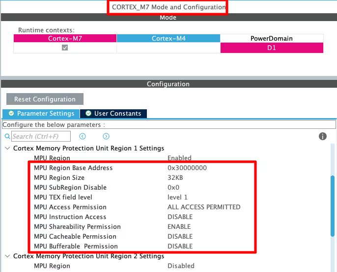
- Here I have selected the 32 KB region so that it will cover our total RAM region, which is around 24KB.
- The rest of the configuration is to set the region as non-cacheable region.
- This would prevent the cache coherency issue between the CPU and the DMA.
- This is explained in the cortex M7 playlist, so do check that out.
Once the project is generated, open the LWIP -> Target -> ethernetif.c file. Here you will some memory locations that needs to be defined in the flash script file.
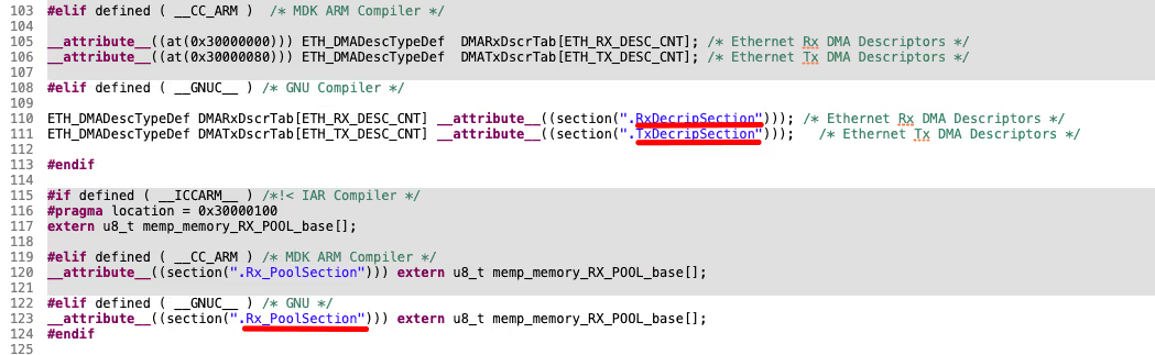
We need to define these memory locations in the flash script file, as per the configuration done in the cubeMX.
Flash script Modification
Below is the code is for the H745 Discovery board according to the configuration done in the CubeMX.
    .lwip_sec (NOLOAD) : {
    . = ABSOLUTE(0x30000000);
    *(.RxDescripSection)

    . = ABSOLUTE(0x30000080);
    *(.TxDescripSection)

    . = ABSOLUTE(0x30000100);
    *(.Rx_PoolSection)
} >RAM_D2Below is the code is for the F7508 Discovery board according to the configuration done in the cubeMX.
.lwip_sec (NOLOAD) :
{
. = ABSOLUTE(0x2004C000);
*(.RxDecripSection)
. = ABSOLUTE(0x2004C0A0);
*(.TxDecripSection)
} >RAMPC Network Configuration (Direct Connection)
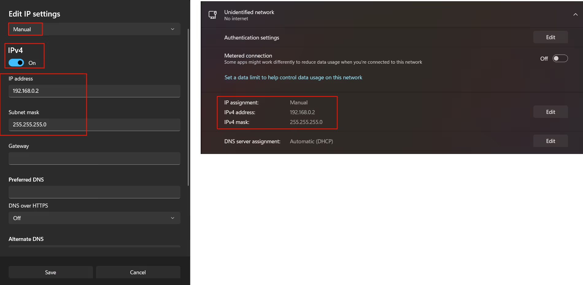
If you are connecting the STM32 board to the Router, there is nothing you need to do at the computer end. But if you are connecting the ethernet cable directly to the computer, you need to configure your computer’s ethernet as per the images shown below.
Below is the configuration for a Windows computer.
Below is the configuration for Mac.
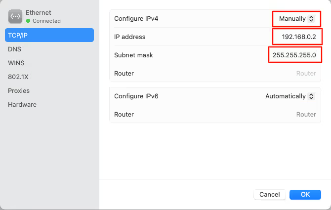
STM32 Ethernet Example: Code, Ping Test & Results
HAL Code for LWIP Ping
Since this tutorial is more focused on connection part, there is not much in the code. We will just test the ping to our IP Address, and the code for the same is shown below.
int main()
{
int wait = 10000000;
while (wait-- >0); // Wait for sometime before initializing the system
MPU_Config();
SCB_EnableICache();
SCB_EnableDCache();
HAL_Init();
HAL_Delay (1000); // wait for some time here
SystemClock_Config();
MX_GPIO_Init();
MX_LWIP_Init();
while (1)
{
MX_LWIP_Process();
}
}Just call the function MX_LWIP_Process() inside the infinite loop. This function will handle all the processing required for the LWIP to run.
Running the Ping Test
Once the hardware and LWIP stack are configured, you can verify Ethernet functionality with a basic ping test.
- Connect STM32 to your PC/router via Ethernet.
- Assign a static IP on your PC (e.g., 192.168.0.100).
- Ping STM32’s static IP (e.g., 192.168.0.123) from your PC’s terminal or CMD:
ping 192.168.0.123You will get the response as shown in the image below.
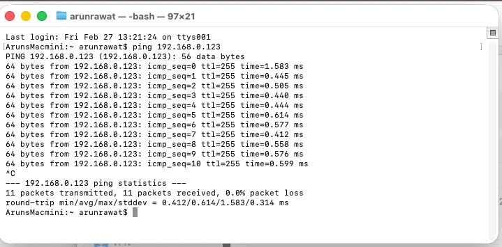
You can see the ping is working on the IP Address that we set during the configuration. This confirms that the configuration is successful and we can proceed with the protocol implementation.
STM32 Ethernet Setup: LWIP Configuration & Ping Test — Video Tutorial
This video walks through the complete STM32 Ethernet setup — hardware connections, CubeMX configuration for RMII/MII, LWIP static IP setup, MPU configuration for Cortex-M7 cache coherency, flash script modification, and a live ping test to verify the connection.
STM32 Ethernet: Troubleshooting & FAQs
Troubleshooting
No link detected / PHY not detected Check the PHY address in CubeMX first (0 for onboard, 1 for external module). Then verify every RMII/MII pin against your board schematic — CubeMX default pin mapping is frequently incorrect and is the #1 cause of Ethernet not working. Also confirm the PHY is receiving its required reference clock (25MHz for MII, 50MHz for RMII).
Ping request timed out Confirm the STM32’s static IP and your PC’s IP are in the same subnet. If connecting directly (no router), make sure the PC’s Ethernet adapter is manually configured with a compatible static IP. Also verify LWIP_ICMP is enabled in CubeMX LWIP options — without it, the STM32 won’t respond to ping at all.
HardFault on Cortex-M7 devices Almost always an MPU configuration issue. The Ethernet DMA region must be marked non-cacheable. Confirm the MPU region covers the full SRAM Ethernet area and that MPU_Config() is called before SCB_EnableDCache() in main().
Code only works in debug mode, not standalone Usually caused by timing. The while(wait-- > 0) startup delay in the code example allows the PHY to initialize before the STM32 starts communicating with it. If it works in debug (which runs slower) but not standalone, this delay is likely too short — increase it.
Ethernet works via router but not direct PC connection Your PC’s Ethernet adapter needs a manually assigned static IP in the same subnet as the STM32. DHCP won’t assign one automatically on a direct link without a router.
Frequently Asked Questions
Conclusion
In this tutorial, you set up STM32 Ethernet from scratch — configuring the MAC and PHY in CubeMX, enabling LWIP with a static IP, placing DMA descriptors correctly in SRAM, fixing the MPU for cache coherency on Cortex-M7, and verifying the connection with a ping test.
The key points to carry forward: always cross-check CubeMX pin assignments against your schematic, get the MPU non-cacheable region right before enabling DCache, and confirm the heap base address doesn't overlap with the Rx buffer region. These three things account for the vast majority of failures reported in the comments.
In the next part, we will build on this foundation to create a UDP Server on STM32 using the LWIP Raw API — sending and receiving UDP packets from a PC with minimal code overhead.
Download STM32 Ethernet LWIP Ping Project Files
Complete CubeIDE project with LWIP configuration, MPU setup, and linker script for Ethernet ping on STM32 — tested on Nucleo F207ZG, F7508 Discovery, and H745 Discovery. Free to download — support the work if it helped you.
Browse More STM32 Ethernet (LwIP) Tutorials
STM32 Ethernet Tutorial (PART 3): UDP Client Tutorial with lwIP (Raw API)
STM32 Ethernet Tutorial (PART 4): TCP Server with lwIP Raw API
STM32 Ethernet Tutorial (PART 5): TCP Client with lwIP Raw API
STM32 Ethernet PART 6 – How to Configure Simple HTTP Webserver
STM32 Ethernet PART 6.1 – Configure HTTP Webserver using SSI


Hi, I’m using the STM32H723 and this tutorial didn’t work for me. I tried to connect through the router instead directly in the PC but it didn’t work also. Based on the comments that I’ve seen on the internet, the Ethernet HAL seems to receive a lot of updates, which cause instability with older versions.
After a long time trying to make this work, I tried the instructions on:
https://community.st.com/t5/stm32-mcus/how-to-create-a-project-for-stm32h7-with-ethernet-and-lwip-stack/ta-p/49308
PS: There are a lot of little configurations, pay attention to them.
There are some troubles with the MPU configurations and the addresses used by Adam but, in the comments, heveskar has attached the path for a STM32 example in their official repository. I just replaced the MPU configs and addresses for those in the example and the ping worked.
.ld:
    .lwip_sec (NOLOAD) : {
    . = ABSOLUTE(0x30000000);
    *(.RxDescripSection)

    . = ABSOLUTE(0x30000080);
    *(.TxDescripSection)

    . = ABSOLUTE(0x30000100);
    *(.Rx_PoolSection)
} >RAM_D2 AT> FLASH
MPU:
MPU_InitStruct.Enable = MPU_REGION_ENABLE;
MPU_InitStruct.Number = MPU_REGION_NUMBER0;
MPU_InitStruct.BaseAddress = 0x0;
MPU_InitStruct.Size = MPU_REGION_SIZE_4GB;
MPU_InitStruct.SubRegionDisable = 0x87;
MPU_InitStruct.TypeExtField = MPU_TEX_LEVEL0;
MPU_InitStruct.AccessPermission = MPU_REGION_NO_ACCESS;
MPU_InitStruct.DisableExec = MPU_INSTRUCTION_ACCESS_DISABLE;
MPU_InitStruct.IsShareable = MPU_ACCESS_SHAREABLE;
MPU_InitStruct.IsCacheable = MPU_ACCESS_NOT_CACHEABLE;
MPU_InitStruct.IsBufferable = MPU_ACCESS_NOT_BUFFERABLE;
HAL_MPU_ConfigRegion(&MPU_InitStruct);
/** Initializes and configures the Region and the memory to be protected
*/
MPU_InitStruct.Number = MPU_REGION_NUMBER1;
MPU_InitStruct.BaseAddress = 0x30000000;
MPU_InitStruct.Size = MPU_REGION_SIZE_256B;
MPU_InitStruct.SubRegionDisable = 0x0;
MPU_InitStruct.AccessPermission = MPU_REGION_FULL_ACCESS;
MPU_InitStruct.DisableExec = MPU_INSTRUCTION_ACCESS_ENABLE;
MPU_InitStruct.IsShareable = MPU_ACCESS_NOT_SHAREABLE;
MPU_InitStruct.IsBufferable = MPU_ACCESS_BUFFERABLE;
HAL_MPU_ConfigRegion(&MPU_InitStruct);
/** Initializes and configures the Region and the memory to be protected
*/
MPU_InitStruct.Number = MPU_REGION_NUMBER2;
MPU_InitStruct.BaseAddress = 0x30004000;
MPU_InitStruct.Size = MPU_REGION_SIZE_16KB;
MPU_InitStruct.TypeExtField = MPU_TEX_LEVEL1;
MPU_InitStruct.IsShareable = MPU_ACCESS_SHAREABLE;
MPU_InitStruct.IsBufferable = MPU_ACCESS_NOT_BUFFERABLE;
I hope this will save you from spending as much time as I did.
Hello and thank you for this detailed guide!!! I think I found a small mistake in the “MPU setup” section above. I may be wrong, but I believe that 0x30000000 + 2*128 bytes + 18 kiB gives 0x30004900, so the LwIP heap starting at address 0x30004000 that you specified would overlap with the Rx buffer to some extent. Shouldn’t the start address of the LwIP heap be defined as 0x30004900 in the example then? Is this correct or have I misunderstood something?
Nope, you got it right. I made a mistake there. But since RXBuffer does not actually occupy 18KB, it works fine. But for larger projects, the care must be taken here.
Hi,
Im learning STM32 and I have a problem. I am able to receive ping into etharp_input function, and I debug data travelling to ethapr_output all the way out into HAL_ETH_Transmit, and there the packet is sent out in
/* Start transmission */
/* issue a poll command to Tx DMA by writing address of next immediate free descriptor */
WRITE_REG(heth->Instance->DMACTDTPR, (uint32_t)(heth->TxDescList.TxDesc[heth->TxDescList.CurTxDesc]));
but nothing is received back to ping caller.
I think that I have a data cache problem, since
/* Wait for data to be transmitted or timeout occurred */
while ((dmatxdesc->DESC3 & ETH_DMATXNDESCWBF_OWN) != (uint32_t)RESET)
goes through normally.
The board is STM32H753ZI
I would appreciate any idea.
BR
Hello,
I am using STM32H750B-DK Board and I am unable to ping it with your code, Could you provide me any points to look for.
Device is working properly , No Hard fault or any thing like that. Your help would be appreciated.
hello. i see your tutorials. a strange thing for me is that when I configure ETH and then add Lwip as a middleware in stmcube, there is no initializer for ETH peripheral in main func or anywhere else. even in your code I see no clue of initializing eth and ethernet dma. so my question is how is this gonna work? because this code does not work for me and the ping times out!
hello. i see your tutorials. a strange thing for me is that when I configure ETH and then add Lwip as a middleware in stmcube, there is no initializer for ETH peripheral in main func or anywhere else. even in your code I see no clue of initializing eth and ethernet dma. so my question is how is this gonna work? because this code does not work for me and the ping times out!
Hello. Thanks for sharing your knowledge.
I’m trying to connect a stm32H7 to lan8720 using freertos and lwip. I couldn’t communicate any packet. actually my code get stuck somewhere in lwip_init. I tried to trace it but it passed the error in debugging mode. could you help me with that? just a clue would be enough. thanks.
I had a similar issue with STM32F746 and it ended up that I configured my ETH as MII and when I checked up the board schematics, it only supported RMII. I corrected that and it has worked as a charm.
HI SIR I AM TRYING TO RECEIVE 13824 BYTES IN STM32F429VET6 IN RAWTCP IHV INCREASED HEAP SIZE MEMORY TO 15*1024?WHAT ELSE I NEED TO CHANGE I N LWIP?
Hi, thank for tutorial is very helpful
I’m building code in NUCLEO H7 144 board and ping OK
But when i reconnect the “Lan wire” – ping is not work, i must reset the power of kit and then work propely.
Have you get any comment for me?
Hi,
The Videos and the documentation are very helpful.
Thanks a lot!
Some parts needs to be updated, tutorial doesn’t work with MX 6.7.0 and STM32CubeH7 Firmware Package V1.11.0 ,thank you in advance
Him
How I can run this project with SPI of STM32H7?
Hi,
Thank you very much
I am new for ethernet, thanks for sharing.
Hi,
Thank you for sharing the detailed information. I am trying to implement the above Ping program using STM32f427VG on a custom designed PCB. In cubemx device configuration tool, I am not seeing a setting under ETH parameters to fill in the Tx/Rx descriptor details as in the tutorial. What could be the possible reason?
Hi, Its working. Sorry, I didn’t check your second video on ethernet.
Thanks again for the content.
Hello, I am also using the STM32F407VG but facing some issue describe below:
My code is working while debugging only and not outside of debug condition.
can you help me ?
hello
first of all thank you
I am working with lan8720 and stm32f767zi. I generated code using stm32cubeid with lwip and eth driver. Code is compiled successful and I connect lan8720 with stm32f767 as per RMII mode. I put MX_LWIP_Init() in main like you Now I flash the programme led is blinking but Ethernet didn’t get IP ,ethernet link not up i can t ping the ip adress .So any one can help me what configuration required while generating code . If any one have sample code please share with me .
Thanks
Hello,
First of all, thanks for all your examples it’s really helpful.
I’m trying to reproduce this example on STM32F439ZI ,
but it doesn’t work when i’m trying to ping it from my computer , when it comes to the STM32F439ZI i dont have access to the MPU Configuration i suppose it’s not a problem .
In ethernetif_input my pbuff is all time == Null then nothing happens, i m also supposed to see my STM at 192.168… when i use netstat -a right ?
If you have any idea from where my problem could be.
Best regards.
Ok then i don’t know why but when i try this with my STM connected in local on my computer it wont work but when i try this directly connected to my router it work .
If you are not using the router, you need to manually configure the ethernet. Check the discord group, I have shared the settings there.
thanks a lot.
Hi blorke,
Is there any breakthrough in your attempts? As I’m planning for the same dude
Did you get the solution? I’m currently working on an ethernet project on STM32F439ZIT6 and I cannot get it through. It would be very helpful if you can guide me on this.
Hi I wanted to thank you very much for this and many other videos that helped me a lot in understanding STM32 boards. I wanted to add to this video that if you’re using an external ethernet module, whose power is controlled by a pin on your board, then you should move MX_LWIP_Init() below the moment you call the HAL_GPIO_WritePin function.
UDP Server and client coming next week. I hope that would help you
me toooo😬