LCD 20X4 using I2C with STM32
In this tutorial we are going to interface LCD 20×4 Display with STM32 using I2C. I am using STM32F103C8 microcontroller and I2C device is PCF8574 with the slave address of 0x4E.
You can use the same code for any other LCD display Type (i.e 16×2, 16X4 etc), except the DDRAM addresses. You can google the addresses for your LCD Type.
ARDUINO ADDRESS
Do not use the address 0x27 and 0x35. This is not arduino and these are not the addresses for your device
Arduino (IDE only… not the mcu) uses 7 bit addressing system and the rest (including STM32) uses 8 bits. Whenever you are using the I2C address, use the full 8 bits for the address. You can find the address for your device in it’s datasheet. The address will (mostly) be either 0x4E for PCF8574, or 0x7E for PCF8574A
VIDEO TUTORIAL
You can check the video to see the complete explanation and working of this project.
HOW TO
Working with these LCD displays is pretty simple. All we need to do is the following :-
- Initialize the display
- Write the address of the DDRAM
- Write the character to be displayed
Initialization
According to the datasheet, To initialize the 20×4 LCD we need to send some sequence of commands to the display. They are as follows:-
Wait for > 45 ms
HAL_Delay(50); // wait for >40mslcd_send_cmd (0x30);
HAL_Delay(5); // wait for >4.1ms
lcd_send_cmd (0x30);
HAL_Delay(1); // wait for >100us
lcd_send_cmd (0x30);
HAL_Delay(10);
lcd_send_cmd (0x20); // 4bit mode
HAL_Delay(10);- Send the function set instruction with the command (0x30) 3 times
- The delay between each command varies as shown above.
- This entire process is than followed by another function set command (0x20)
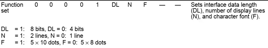
lcd_send_cmd (0x28); // Function set --> DL=0 (4 bit mode), N = 1 (2 line display) F = 0 (5x8 characters)
HAL_Delay(1);Send the function set command (0x28) to set the display in 4 bit mode (DL=0), 2 line display (N=1) and 5×8 fonts (F=0)
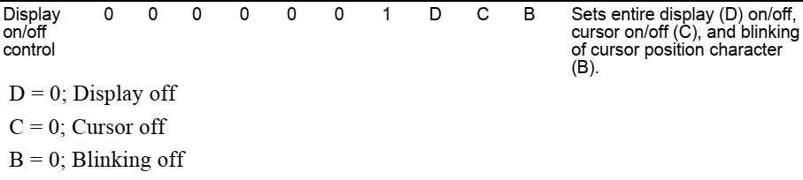
lcd_send_cmd (0x08); //Display on/off control --> D=0,C=0, B=0  ---> display off
HAL_Delay(1);- Send the command to the Display On/OFF Control
- Display off (D=0), Cursor off (C=0) and Blink OFF (B=0)

lcd_send_cmd (0x01);  // clear display
HAL_Delay(1);Clear the Display by Sending 0x01.
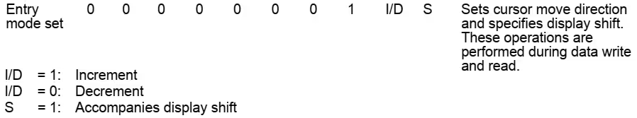
lcd_send_cmd (0x06); //Entry mode set --> I/D = 1 (increment cursor) & S = 0 (no shift)
HAL_Delay(1);Set the entry mode of your choice. I am setting Cursor move as increment (I/D=1) and display shift as OFF (S=0)
lcd_send_cmd (0x0C); //Display on/off control --> D = 1, C and B = 0. (Cursor and blink, last two bits)Turn the display ON (D=1) along with the choice for cursor and blinking. I am setting both to 0 (C=0, B=0)
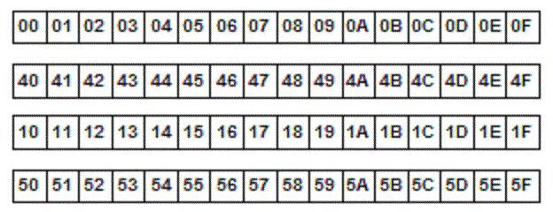
DDRAM ADDRESS
Addresses for the DDRAM of the LCD 20×4 is shown below.
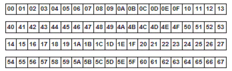
While setting an address we need to OR (|) it with the 0x80. For eg if I want to set the cursor to 2nd row, I have to set the address as (0x80|0x40).
If you want to use a 16×4 LCD than the addresses for the DDRAM are shown below. Use the same code with just the change in address.
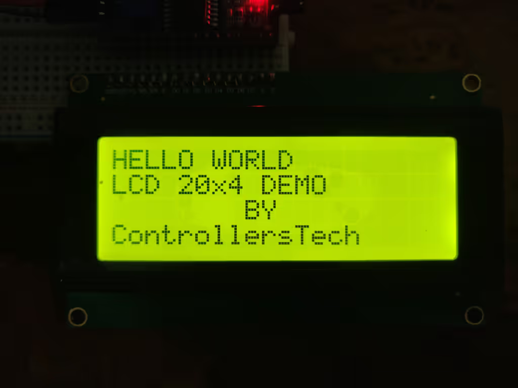
RESULT


Hi, I used your library and works unstable, some times yes and others not, could be the frecuency of scl?, some clock configuration? I saw there are some options for frecuency output selection in the ioc configuration screen
Try using the pull up resistors on the SCL and SDA pins. The baud 100KHz is standard , but you can try 400KHz also. See if it does any improvements
is this work for stm32f407 or not?? i changed the #include “stm32f1xx_hal.h” to #include “stm32f4xx_hal.h” but i got nothing on display
Hello everyone !
I tried this tutorial, it’s very useful, thanks !
I would like to print on my LCD display some values like voltage (using a potentiometer plugged on Analong input).
Is there any “printf” function in this project ? I can’t find it…
Thank you very much !
convert the data to string using sprintf function
send the data to lcd using lcd_send_string
PS: don’t look for arduino reference everywhere. Not every library is written as per arduino terminology.
it is a very useful video and tutorial. I use stm32f429zi to generate a pulse for the Triac, so i have a timer output compare that give me the pulse but when i link the lcd display , the display and your code works fine but the pulse misses. The output of timer1 is 3,3 V instead of the pulse. What can i do to resolve? thank you sir
That is not related to display. There must be something in the code or the Pins you are selecting. It is highly unlikely that using a display is going top mess up the timer.
i have initialize the timer in one pulse mode , in the ch2 i have a square wave input and the ch2 i have the output(pulse for a thyristor)
PLEASE HELP ME!
If i am using a keypad, how can i send the pressed bottun only one time to the LCD?
I use the lcd_send_string function but it keeps writting the number as long as the bottun is pressed.
I mean so a function: lcd_send_char().
do this::
when the button is pressed
{
wait for the button to release;
send to the display;
}
I have just found this and am working this example with a F411RE and getting some errors: /Drivers/STM32F4xx_HAL_Driver/Inc/stm32f4xx_hal.h:220:1: error: unknown type name ‘HAL_StatusTypeDef’
I have replaced your include file in i2c-lcd.h with stm32f4xx_hal_conf.h which solved some errors.
How can I move forward ?
Hi
Where i found DDRAM pleace. I have got lcd16x4 (LCD-AC-1604A-FHW K/W-E6 C) and when i applaying ur code i saw olny black squares. I try adjust contrast but didn’t help. (Yes i change slave id )
lcd and arduino works fine
what I2C device are you using?
What address have you changed ?
And what about DDRAM address? I have put the picture for DDRAM address for 16×4.
in i2c-lcd.c
#define SLAVE_ADDRESS_LCD 0x27 // change this according to ur setup
i need to change adress because my lcd (and driver ) has 0x27
DDRAM it’s my mistake i see
this is length of my data
Your LCD don’t have any address. It’s the address of the I2C device that is attached to the LCD.
Also you are not using arduino, so the address is 8 bit wide now
Use the address 0x4E, not 0x27
if i use like this
#define SLAVE_ADDRESS_LCD 0x4E
i saw glitches but no more black squares
reset the device once or twice
try removing the VCC pin and connect back and reset again
0x4E works but i sends “a” and i see “III” in one square and next square blinking cursor
I’am execute your raw program with first line of text (hello world)
and i got glitches
bellow foto
https://drive.google.com/file/d/19dYTQnZt5cJ_qwcAQr4mBS6Lva50htsq/view?usp=sharing
Comment the line “lcd_send_cmd (0x28);” and it ‘ll work for 1604a LCD
my i2c device is PCF8574
come to that discord group…
it’s works only 20×4 not 16×4 idk where is mistake
The black squares mean no lcd init.
use your address in the form (0x4E<<1) or (0xF7<<1) or the right address for your own I2C LCD
sorry.
The I2C address in i2c-lcd.c most be in the form:#define SLAVE_ADDRESS_LCD (0x3F << 1) // change this according to your setup
Why is that ?
You must be using PCF8574A, so the address for your device is 0x7E.
I have used PCF8574, so the address is 0x4E
Good tutorial with some things to be fixed.
The I2C address in i2c-lcd.h most be in the form:
#define SLAVE_ADDRESS_LCD (0x3F << 1) // change this according to your setup
how can i send a data with 4 number ?
use sprintf to converts the number to characters
char buf[4];
sprintf (buf, “%d”, num);
lcd_send_string (buf);
Hi
this is wrong libraey for i2c lcd 2004
ok and what’s wrong ?
I am a beginner of the stm32 boards so could you please given a LCD
code for stm32f4discovery board
download button is just above the comment
Thanks sir, but I do every step as you did successful(build and debug) and I get empty lcd. I have tried address 0x4E and 0x27(it works for arduino and pi), also I increased the delay before initialization and same result?
thank you for this great tutorial.
but I m facing a problem of displaying garbage data on LCD when the MCU is reset. Though I have used i2c module with 20×4 LCD along with bypass caps on Vcc of i2c module, this problem is very frequent and since I have to commercialize my work, I m facing great loss because of this.
Could u please suggest some software and hardware changes
Try adding more delay after initialization.
Hi nice post!! do you have a command to turn off the lcd´s light, like a standby mode.
No. But i think, i can make one..
Let me give it some thought
You have library i2c-lcd.h i2c-lcd.c ?????