Managing Multiple UARTs in STM32
Few months ago, I wrote a tutorial about using head and tail in UART to receive and transmit data of unknown length. In that tutorial, I only used single UART to communicate with the computer. Now, in order to use some serial communication based sensors for eg- ESP8266, GPS, GSM, etc, we need to have one dedicated UART PORT to communicate with the sensor, and another UART PORT should be connected to the computer.
So, in this tutorial, we are going to manage 2 UARTs with Head and Tail method. Both would be able to receive and transmit data of unknown length. And after reading this, you will be able to use all those sensor, that require serial transmission.
In this tutorial, i am going to use STM32F446RE along with CUBEIDE and ESP8266. Which is a wifi device and works with serial transmission. Now for the sake of simplicity, let’s assume that I don’t know what response is it going to send, after I supply any AT command to this device.
UPDATE 2
L4 series and G series MCUs have some issues with UART_ISR_TXE. If you are having issues even after making changes according to UPDATE 1, then Replace the Uart_isr with the file https://controllerstech.com/wp-content/uploads/2020/10/uart_isr_multi_new.c
UPDATE 1
Those, who have errors in the Uart_isr function, like DR or SR registers are not present, replace the Uart_isr code with the one provided in this file https://controllerstech.com/wp-content/uploads/2020/04/Uart_isr.c
VIDEO TUTORIAL
You can check the video to see the complete explanation and working of this project.
CubeMX Setup
The setup part is very simple. In the figure below you can see that I have enabled 2 UARTs i.e. USART1 and USART2. Both of them have the BAUD RATE of 115200, and interrupt is enabled.
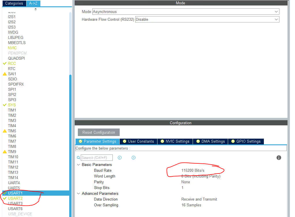
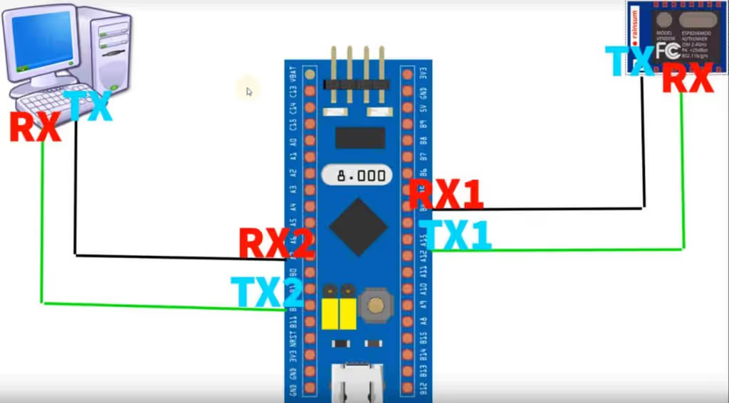
UART1 is connected to ESP8266 in a way that the RX pin of UART is connected to TX pin of WiFi, and TX pin of UART is connected to RX pin of WiFi. UART2 is connected to the computer in the same manner.
Some insight into the code
After generating the project, you have to include the library files into the project. Basically UartRingbuffer_multi.c file will go in the src folder and UartRingbuffer_multi.h file will go in the inc folder.
#define device_uart &huart1
#define pc_uart &huart2Above, the UARTs are being defined for the respective handlers. If you are not using uart1 or uart2, you can change them here. Don’t change the name, or else you have to make the changes everywhere in the code .
void Ringbuf_init(void)
{
  _rx_buffer1 = &rx_buffer1;
  _tx_buffer1 = &tx_buffer1;
  _rx_buffer2 = &rx_buffer2;
  _tx_buffer2 = &tx_buffer2;

  /* Enable the UART Error Interrupt: (Frame error, noise error, overrun error) */
  __HAL_UART_ENABLE_IT(device_uart, UART_IT_ERR);
  __HAL_UART_ENABLE_IT(pc_uart, UART_IT_ERR);

  /* Enable the UART Data Register not empty Interrupt */
  __HAL_UART_ENABLE_IT(device_uart, UART_IT_RXNE);
  __HAL_UART_ENABLE_IT(pc_uart, UART_IT_RXNE);
}Ringbuf_init initializes both the Ring buffers. This must be called in the main file before working with Ring buffer.
int IsDataAvailable(UART_HandleTypeDef *uart)
{
	if (uart == device_uart) return (uint16_t)(UART_BUFFER_SIZE + _rx_buffer1->head - _rx_buffer1->tail) % UART_BUFFER_SIZE;
	else if (uart == pc_uart) return (uint16_t)(UART_BUFFER_SIZE + _rx_buffer2->head - _rx_buffer2->tail) % UART_BUFFER_SIZE;
	return -1;
}IsDataAvailable checks if the data is available to read in the input buffer. The parameter, UART_HandleTypeDef *uart, is the UART where you want to check for the availability of the data.
This function returns ‘1’ if the data is available.
int data = Uart_read(pc_uart);Uart_read reads the data from the input uart and save this data in the corresponding RX buffer. It also increments the tail, so as to indicate that the data has been read from that position, and this makes the position available to store new incoming data.
The parameter is the uart, that you want to read the data from.
Uart_write(data, wifi_uart);Uart_write writes the data in the TX buffer to the input UART. After writing the data, the tail gets incremented and this makes up space for the new data to be stored in the TX buffer.
/* function to send the string to the uart */
void Uart_sendstring(const char *s, UART_HandleTypeDef *uart);Uart_sendstring sends the input string to the input UART.
/* Copies the entered number of characters (blocking mode) from the Rx buffer into the buffer, after some particular string is detected
* Returns 1 on success and -1 otherwise
* USAGE: while (!(Get_after ("some string", 6, buffer, uart)));
*/
int Get_after (char *string, uint8_t numberofchars, char *buffertosave, UART_HandleTypeDef *uart);Get_after gets the numberofchars (number of characters) after the input string is received in the incoming stream of data. These characters would be saved in the buffertosave buffer. Once the characters are received, the function will return a ‘1’.
It must be used in the if loop so that it can wait for the characters to be received. As the function is looking for the characters in the incoming data, the tail value in the RX buffer also increments here.
/* Copy the data from the Rx buffer into the buffer, Upto and including the entered string
* This copying will take place in the blocking mode, so you won't be able to perform any other operations
* Returns 1 on success and -1 otherwise
* USAGE: while (!(Copy_Upto ("some string", buffer, uart)));
*/
int Copy_upto (char *string, char *buffertocopyinto, UART_HandleTypeDef *uart);Copy_upto Copies the data from the Rx buffer of the given uart, into the entered buffer. But it will copy until the entered string is reached.
/* Wait until a paricular string is detected in the Rx Buffer
* Return 1 on success and -1 otherwise
* USAGE: while (!(Wait_for("some string", uart)));
*/
int Wait_for (char *string, UART_HandleTypeDef *uart);Wait_for will wait until a predefined string is received in the Rx buffer of the entered uart. If it does, than the function will return 1.
/* Look for a particular string in the given buffer
 * @return 1, if the string is found and -1 if not found
 * @USAGE:: if (Look_for ("some string", buffer)) do something
 */
int Look_for (char *str, char *buffertolookinto);Look_for will look for a particular string inside the given buffer. If the string is found, it will return 1.
Working
First of all I have defined the new names to the uart handlers as shown below
#define pc_uart &huart2
#define wifi_uart &huart1Next we need to initialize the ring buffer in the main function
Ringbuf_init();In the while loop, if the controller receives the data from device, it will send it to the PC. And if it receives the data from the PC, it will send it to the device. This way it will act as a mediator in between device and computer.
 while (1)
  {
    if (IsDataAvailable(pc_uart))
    {
     int data = Uart_read(pc_uart);
     Uart_write(data, wifi_uart);
    }

    if (IsDataAvailable(wifi_uart))
    {
     int data = Uart_read(wifi_uart);
     Uart_write(data, pc_uart);
    }
  }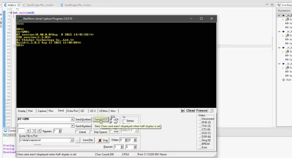
AT+GMR command is sent from the computer to the controller. Which, on receiving this data, will send it to the device. The device sends the response, which is again received by the controller and than sent back to the computer. That response is being displayed on the picture above.
Now the the very important function i.e. Get_after. Basically, it gets the entered number of characters after the predefined string is detected in the incoming data.
  while (1)
  {
	  if (IsDataAvailable(pc_uart))
	  {
		  int data = Uart_read(pc_uart);
		  Uart_write(data, wifi_uart);
	  }

	  if (IsDataAvailable(wifi_uart))
	  {
		  if (Get_after("AT version:", 8, buffer, wifi_uart))
		  {
			  Uart_sendstring("AT VERSION=", pc_uart);
			  Uart_sendstring(buffer, pc_uart);
		  }
	  }
}In the example above, we want to get 8 characters after the string “AT version:” in the received data, which is sent from wifi_uart. And these characters will be saved in buffer. After the characters are received, the if loop will be executed, and these characters will display on the serial terminal.
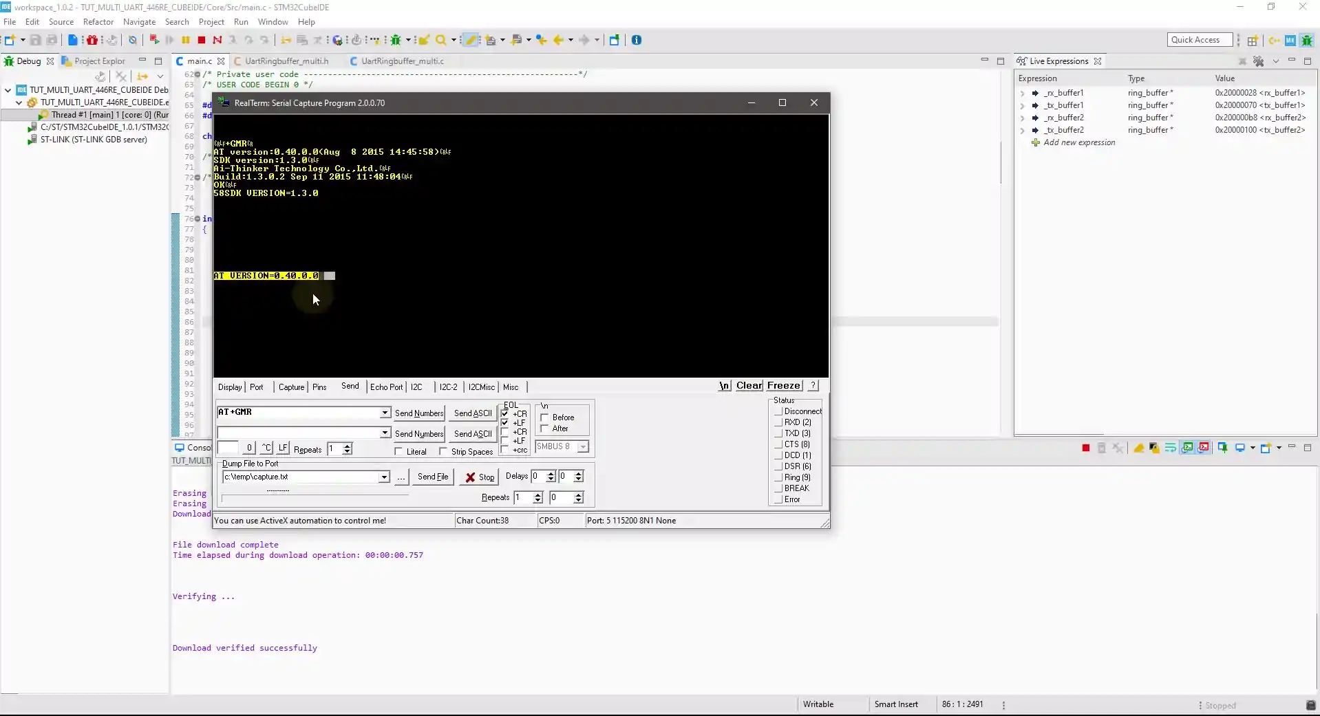
As you can see above, the contents of the if loop being displayed on the serial terminal along with the 8 characters that we received. Note that, the tail in the RX buffer increments while the data is being checked for the string, so you have to use this function very carefully.


Hello, first of all thank you for this great tutorial.
I tested this example on a stm32L475IOT, I have a problem, when I send the AT command, it reads only one character, so how to make it read all the data transmitted as a string.
Thank you in advance
what reads one character ? The library have a lot of functions, use them.
uart_read will only read 1 character.. you have to use other functions.. read the source file and use the function that fit your requirement.
Hi! Do you have a similar example but with registers? Thank you!
Hello, first of all thank you for this great tutorial
My question is, can this code and library be used for three modules with appropriate changes?
I am going to control two Quectel MC60 microcontrollers by a stm32f103c8t6, through the uart protocol, and I need to see the information exchanged between the microcontrollers in another uart port(a total of three ports are needed) on the computer so that I can be sure of the correctness of the information and their operation.
Thank you in advance
yes it can be used, but you need to modify the library at appropriate places.
thank you so much
Bonjour,
La fonction Get_after n’est pas la même entre la vidéo et dans le code téléchargeable.
si j’envoie deux fois la fonction AT+GMR la deuxième fois n’est pas pris en compte.
quel est le bon code ?
Merci beaucoup
Hello. First of all, thanks for the portable code of ring buffer.
My App:
I am trying to develop a application wherein I will be sending command through python script over serial port. On the STM32 side, I will be decoding the command and taking actions accordingly
Problem statement:
The code works fine when sending & receiving of any characters. But when I try to send string from python over serial port like ser.write(b‘\nABC’), the control gets stuck in ISR on STM32. Any idea?
shouldn’t happen like that.
Don’t put breakpoints in the code, rather analyze the RX buffer in the live expression.
Hello! Nice job! your web is awesome. Could you tell me if they work for the H7 family? I try with both Uart_isr functions and works to send data, but not receive. Exactly the model is stm32h743vit… should I change something else?
Tks!
Try the newer one. Uart ring buffer using IDLE line..
Excusme because define twice rx_buffer1,tx_buffer1, etc?
Hi, I could not find the uartringbuffer_multi.c and Uartringbuffer_multi.h files in your Github https://github.com/controllerstech/stm32-uart-ring-buffer. If you could direct me to the page, it will be really helpful. Thanks in advance.
I haven’t written it. I am going to write these functions for the IDLE LIne DMA. That one is better.
Thank you for the reply.
Hello, I appreciate your articles! I have one question.
I like to send the data after
Uart_write(data, wifi_uart);
additionally to the USB CDC uart with
uint8_t CDC_Transmit_FS(uint8_t* Buf, uint16_t Len).
How can i achieve this? If I send directly the data via
CDC_Transmit_FS(*data, 1)
I’ loss some bytes.
hello sir . I am developing a project that is contained has 3 uart port . how can i manage it with ring buffer method
i have found an error in “Uart_flush (UART_HandleTypeDef *uart)”
you only set “_rx_buffer1->head = 0;”
but rxbuffer->tail must also be set to “0”
in older version you set “_rx_buffer1->head = _rx_buffer1->tail;” this is working
or set both to “0”
hi its good but if we want to use multi uart with rx circular dma ….
so whats your solution ? i dont have any idea and cant find good source for stm32f4xx
I appreciate the ring buffer code you presented. I am getting a number of compiler warnings such as this: “warning: conversion to ‘int’ from ‘size_t {aka unsigned int}’ may change the sign of the result [-Wsign-conversion]” in multi_uart.c mainly. I typically “turn up” the warnings and I treat most of them as errors.
I understand the error and am wondering why you chose to use int variables instead of uint variables in most of the functions. Eg. strlen returns a long uint but it is being assigned to an int. Later in loop, the counter is an int being compared to a uint.
I could not yet find a case where a uint causes problems with most of the code. Am I missing something here that would cause issues? Thank you very much.
Hello Sir,
This is exactly what I wanted but I want to code on Arduino IDE using uart1 and uart2 on STm32F103C8T6.
Regards,
Navneet
have you solved this problem?
this is not arduino forum…
How to take data from mobile app to Bluetooth to MCU to Wi-Fi web server(Thingspeak).
I
you can use 2 uarts, one connected to bluetooth and another to wifi. Check out my video on managing multiple uarts
Hello,
Library works very good. But, if possible, could you, Sir, add an extra function like Copy_upto but without including the indicated string?
Regards.
Thank you.
it’s very simple just add yourself. just let it copy_upto, but then you don’t read the last n characters from that buffer (where the data was copied). n is the length of string that you don’t want to include.
sir,data is transmitted from PC to microcontroller is done. then data is not coming from gsm to uart.
Hello, great work!
Could you tell me if it is possible to handle an additional uart port? For this, should I define a tx_buffer and rx_buffer3?
and the functions “Uart_peek” and “Copy_upto” can be executed in non-blocking way?
Regards. Thank you!
yeah u can use another uart. Go through the code very carefully. I have created the the instances for 2 UARTs at a lot of different places. you need to add another one there.
all the functions can work in non blocking manner, but expect a huge data loss then. This is because we don’t know when and how much of the data is being received
Sir,
Data is transmitted from PC to Microcontoller. But response not coming from ESP8266 because previous program is running on that.
Those, who have errors in the Uart_isr function, like DR or SR registers are not present, replace the Uart_isr code with the one provided in this file – The file in Google Drive doesn’t exist… 🙁 Could you share again? I’m developing this project in NUCLEO-F767ZI but it seems that code in Uart_isr doen’s work properly. Thanks in advance
https://controllerstech.com/wp-content/uploads/2020/04/Uart_isr.c
Ok, Now it works perfectly. Thank you very much. Regards.
hi dear
i every day check your site to see your usefull education
i have a problem to run ev1257 remote control 433 mhz with stm32 can you help me
sincerley love yours mohammad
Hi mohammad, i remember you sent me mail about this also. I will advice that you use this tutorial to interface ev1257. Anyway i am working on something similar right now, and once done, will contact you.
thanks alot
i will wait and every day check your tutorials goodbless you
sincerely love yours mohammad