Updated On: March 23, 2026
How to Generate 3-Phase PWM Using Synchronized STM32 Timers
Generating 3-phase PWM signals is essential in applications such as BLDC motor control, inverters, and power electronics systems. In these applications, three PWM signals must be produced with a precise 120° phase shift between them. Achieving this accurately using software delays is difficult and unreliable. That’s where STM32 timers and their synchronization features become extremely powerful.
STM32 advanced and general-purpose timers support master–slave synchronization, allowing one timer to control the triggering and timing of others. By configuring one timer as the master and the remaining timers as slaves, we can generate perfectly synchronized PWM signals with controlled phase offsets — entirely in hardware, without CPU intervention.
In this tutorial, we will configure STM32 timers to generate three synchronized PWM outputs, understand how the trigger and synchronization mechanisms work internally, and see how this approach ensures stable and precise multi-phase signal generation suitable for real-world motor control applications.
This is 6th tutorial in the STM32 Timer series, and today we will cover yet another Timer synchronization feature where we will generate a 3 phase PWM waveform.
Generating Phase-Shifted PWM Using Multiple Timers
To generate a proper 3-phase PWM signal, we need three PWM outputs with an exact 120° phase shift between them. While it may seem possible to start three timers manually with software delays, this approach cannot guarantee precise synchronization. Instead, STM32 timers provide a powerful hardware synchronization mechanism that allows multiple timers to operate in perfect alignment.
Let’s understand why software delay is not suitable and how hardware synchronization solves the problem.
Why Software Delay Cannot Generate Accurate Phase Shift
A common idea is to start Timer1, then delay in software, start Timer2, delay again, and start Timer3. In theory, this should create a phase difference.
However, this approach has major limitations:
- CPU latency introduces unpredictable delay.
- Interrupts and other tasks affect timing accuracy.
- The delay depends on compiler optimization and clock variations.
- The phase shift will drift over time.
Even a small timing mismatch can distort the waveform, which is unacceptable in applications like motor control, inverters, and power electronics, where precise 120° separation is critical.
Therefore, software-based phase shifting is unreliable for accurate multi-phase PWM generation.
Hardware Synchronization Using TRGO
STM32 timers support internal synchronization using a Master–Slave architecture.
- One timer is configured as the Master.
- It generates a trigger output signal called TRGO (Trigger Output).
- Other timers are configured as Slave timers.
- Slave timers use the internal trigger (ITR) line connected to the Master.
When the Master timer starts or updates, it automatically triggers the Slave timers in hardware — without CPU involvement.
This ensures:
The synchronization happens entirely inside the timer hardware block, making it ideal for generating clean multi-phase PWM signals.
Calculating 120° Phase Shift for 3-Phase PWM
For a 3-phase system, each signal must be separated by:
If the PWM period corresponds to a timer count value ARR, then:
- 120° phase shift = 3ARR
- 240° phase shift = 32×ARR
For example:
If ARR = 3000
Then:
- Phase A starts at 0
- Phase B starts at 1000
- Phase C starts at 2000
By preloading the counter of slave timers or using slave mode with trigger delay, we can create this exact offset in hardware. This guarantees a mathematically precise 120° separation between the three PWM signals.
STM32CubeMX Configuration
We will start with the clock configuration for this project. The image below shows the clock tree.
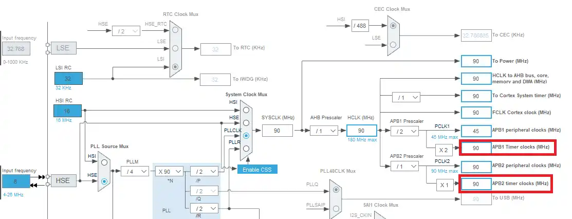
Here both the APB Timer clocks are running at 90 MHz. We will use the Timers 1, 2 and 3 to create the 3 PWM signals. Here TIM1 is connected to the APB2 bus and TIM2 and 3 are connected to the APB1 bus. I am keeping the clock same for these buses so that we can use the same configuration for the timers.
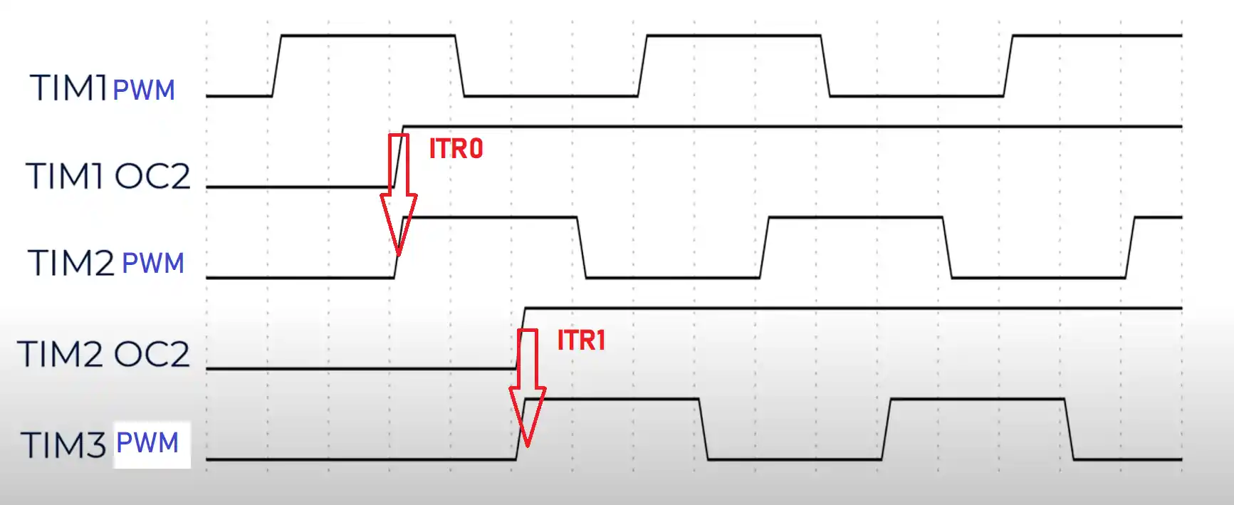
The internal Trigger system for these Timers is shown below
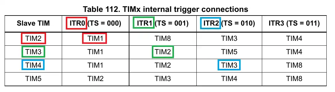
Here you can see the TIM2 as a slave can be controlled by the master TIM1 using the ITR0 signal. Similarly, the TIM3 can be controlled by the TIM2 using the ITR1 signal.
We will use these signals to trigger the counter of the slave Timers, when the master counter reaches a predefined value.
- Basically the TIM1 will generate a PWM signal on channel 1.
- When the counter 1 will reach 33% of the ARR value, TIM1 Output Compare on channel 2 will go high.
- This will trigger the ITR0 signal, and TIM2’s counter will start at that moment.
- Similarly, when the counter 2 will reach 33% of the ARR value, TIM2 Output compare on channel 2 will go high and it will trigger the ITR1 signal.
- TIM3 counter will start at this moment.
Timer Configuration
The image below shows the configuration for all three Timers.

- Here the TIM1 is the master for TIM2, so there is no slave mode for it.
- TIM2 is the slave for TIM1, which can be triggered by the ITR0 signal. It is also the master for TIM3.
- TIM3 is only the slave for TIM2, which can be triggered by the ITR1.
Note:
Calculate the ARR and CCR values for the STM32F4 Timers using the STM32F4 PWM Tool:
https://controllerstech.com/tools/stm32f4-pwm-calculator/
All the timers have the channel 1 set as the PWM output, and channel 2 as the Output compare (Except TIM3 since it’s not the master).
The output compare signal is used as the trigger source for the next Timer in line.
Since both the APB Timer clocks are running at the same 90MHz frequency, I have used the similar configuration for all three timers.
Here the timers will run at 100 Hz frequency with the PWM duty as 40%.
You can check the PWM tutorial if you don’t understand this https://controllerstech.com/pwm-in-stm32/
The pulse value (AKA CCR value) for the output compare channel is set at 3333. This is basically the 33% of the ARR value, which is 9999.
The Pinout
The pinout for this project is shown below
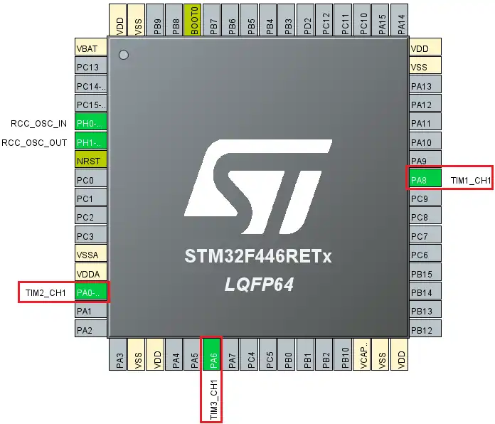
These 3 pins are basically the PWM pins from each timer. I have connected them to the 3 channels of the Logic Analyzer.
STM32 HAL Code for 3 phase PWM
There is not much to do in the code. Since we are using the PWM and output compare, we will simply start both the functions for the timers.
  /* USER CODE BEGIN 2 */
  HAL_TIM_PWM_Start(&htim1, TIM_CHANNEL_1);
  HAL_TIM_OC_Start(&htim1, TIM_CHANNEL_2);

  HAL_TIM_PWM_Start(&htim2, TIM_CHANNEL_1);
  HAL_TIM_OC_Start(&htim2, TIM_CHANNEL_2);

  HAL_TIM_PWM_Start(&htim3, TIM_CHANNEL_1);
/* USER CODE END 2 */Here I have started the PWM for channel 1 and Output Compare for channel 2 for TIM1 and TIM2. Since TIM3 is not the master for any timer, we will only start the PWM for it.
Result of the 3 phase PWM
First let’s see the frequency and duty cycle for the PWM signal.
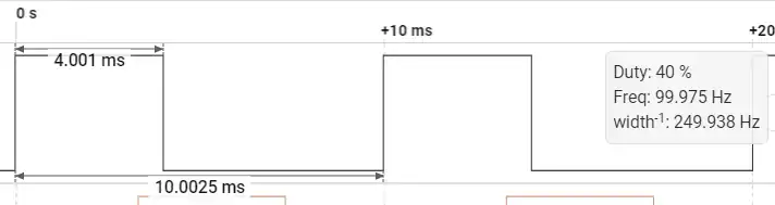
Here you can see the frequency is approximately 100 Hz with the duty of 40%. This is as per the configuration we did for the PWM signal.
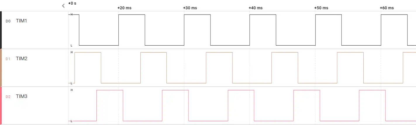
Now we will see the three waveforms we got.

Here I have set the three markers at the rising edges of all three PWMs. On the right you can see the timestamps of these rising edges relative to the TIM1.
We know the time period of the PWM signal is 10ms, so the PWM2 starts at 3.3ms i.e. 33% of 10ms. Similarly the PWM3 starts at 6.6ms i.e 66% of 10ms.
Basically all three signals have 120 degrees phase difference between them.
This difference will remain constant throughout.
Video Tutorial
STM32 3-Phase PWM Using Timer Synchronization – Video Tutorial
This video demonstrates how to generate 3-phase PWM signals using STM32 timer synchronization. You’ll learn how to configure TIM1 as the master timer, use OC2 to generate TRGO, and trigger TIM2 and TIM3 through internal trigger lines (ITR0 and ITR1). The step-by-step walkthrough covers CubeMX setup, master–slave chaining, phase shift configuration, and oscilloscope verification of the 120° phase-shifted PWM outputs.
Watch the VideoConclusion
Generating 3-phase PWM using STM32 timer synchronization provides a precise and hardware-controlled solution for applications like motor control, inverters, and power electronics. By configuring TIM1 as the master and chaining TIM2 and TIM3 through internal trigger connections (ITR lines), we can create stable and accurate 120° phase-shifted PWM signals without relying on software delays. This approach ensures perfect alignment between phases while keeping the CPU free for other tasks.
Using the master–slave timer mechanism not only improves timing accuracy but also makes the system scalable and easier to maintain. Once the synchronization structure is properly configured, frequency and duty cycle adjustments can be made centrally while preserving the phase relationship. This hardware-based synchronization is one of the most powerful features of STM32 timers and is essential for building reliable multi-phase PWM systems.
Browse More STM32 Timer Tutorials
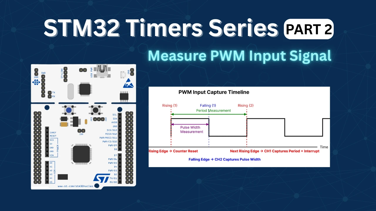
STM32 Timers (Part 2): How to Measure PWM Input Signal
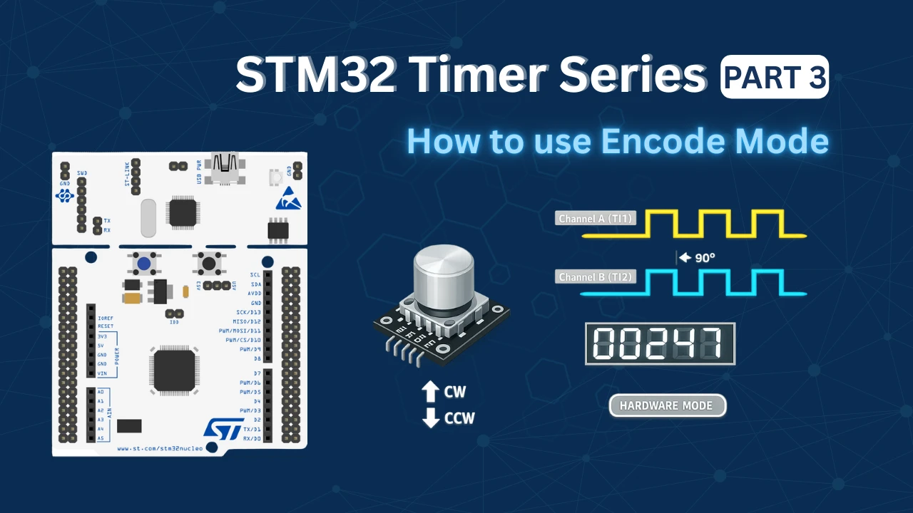
STM32 Timers (Part 3): How to use the Timer Encoder Mode
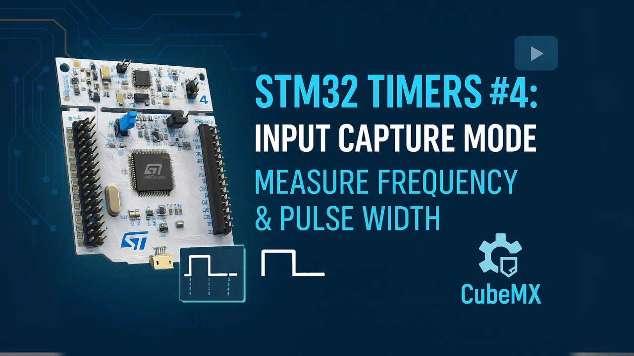
STM32 Input Capture: Measure Frequency & Pulse Width
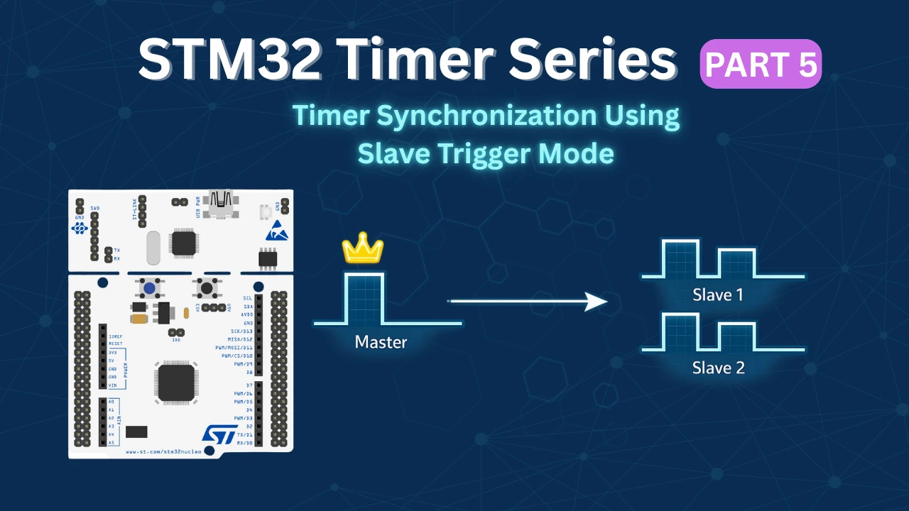
STM32 Timer Synchronization: Slave Trigger Mode with CubeMX & HAL
STM32 Timers (Part 7): Timer synchronization using Slave Reset mode
STM32 Timers (Part 8): How to Create a 48-Bit Counter by Cascading Timers
STM32 Timers (Part 9): One Pulse Mode (OPM) – Generate Precise Triggered Pulses with Delay and Width Control
STM32 Three-Phase PWM Project Download
STM32 Three-Phase PWM FAQs


Thanks a lot your post.
I need to adjust the shift phase of signals dinamically in the main program. I have tried changing the value of CCR2 of timers TIM1 and TIM2, but it does not work. Here is the sentences:
__HAL_TIM_SET_COMPARE(&htim1, TIM_CHANNEL_2, 200);
__HAL_TIM_SET_COMPARE(&htim2, TIM_CHANNEL_2, 200);
Do you know if the shift phase can be adjusted dinamically and How I can do it?
Thanks.
Can this method work for 4 phase ?
You can try… I am not sure, but it should work I guess.
Thank you
Here I am using the ADC to adjust the frequency max. 50Hz
while (1)
{
/* USER CODE END WHILE */
adc_val = ADC_Read();
a = (uint16_t)(((float)(adc_val)/4095)*20000); // cal Autoreload Max. 50Hz
b = (uint16_t)((float)(a)*0.333); // Phase 120 Degree
c = a/2;
__HAL_TIM_SET_AUTORELOAD(&htim1, a);
__HAL_TIM_SET_AUTORELOAD(&htim2, a);
__HAL_TIM_SET_AUTORELOAD(&htim3, a);
__HAL_TIM_SET_COMPARE(&htim1, TIM_CHANNEL_2, b);
__HAL_TIM_SET_COMPARE(&htim2, TIM_CHANNEL_2, b);
//__HAL_TIM_SET_COMPARE(&htim3, TIM_CHANNEL_2, b);
__HAL_TIM_SET_COMPARE(&htim1, TIM_CHANNEL_1, c);
__HAL_TIM_SET_COMPARE(&htim2, TIM_CHANNEL_1, c);
__HAL_TIM_SET_COMPARE(&htim3, TIM_CHANNEL_1, c);
HAL_Delay(100);
/* USER CODE BEGIN 3 */
}
Here the code for calculate and set the CCR.
while (1)
{
adc_val = ADC_Read();
a = (uint16_t)(((float)(adc_val)/4095)*10000); // cal duty cycle
//a = (uint16_t)(((adc_val)/4095)*10000); // cal duty cycle
__HAL_TIM_SET_COMPARE(&htim1, TIM_CHANNEL_1, a);
__HAL_TIM_SET_COMPARE(&htim2, TIM_CHANNEL_1, a);
__HAL_TIM_SET_COMPARE(&htim3, TIM_CHANNEL_1, a);
HAL_Delay(100);
}
Here is for ADC read function, the ADC set up can be done by CubeMX, sir.
uint16_t ADC_Read(void)
{
uint16_t adcVal;
/* Enable ADC and start ADC conversion */
HAL_ADC_Start(&hadc1);
/* Wait for ADC conversion to be completed */
HAL_ADC_PollForConversion(&hadc1, 1);
/* Get ADC value from ADC data register */
adcVal = HAL_ADC_GetValue(&hadc1);
/* Stop ADC conversion and disable ADC */
HAL_ADC_Stop(&hadc1);
return adcVal;
}
Hello, I have an idia to use ADC to adjust speed(CCR), Thanks You very much, sir.
hello,
Thank you very much, Sir