Home ▸ STM32 Tutorials ▸
Updated On: February 8, 2026
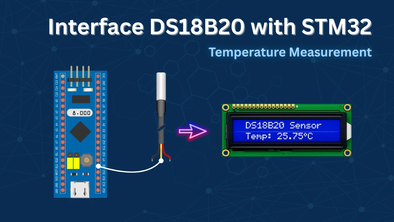
How to interface DS18B20 with STM32
The DS18B20 is a popular digital temperature sensor that provides accurate temperature measurements over a 1-Wire communication interface, requiring only a single data line along with ground. In this tutorial, we will learn how to interface the DS18B20 temperature sensor with an STM32 microcontroller using STM32CubeIDE and HAL libraries.
You will understand how the 1-Wire protocol works, including the reset sequence, presence detection, and the precise timing required to read and write data bits. The tutorial also covers generating microsecond delays using a timer, reading temperature data from the sensor, converting it into human-readable form, and displaying the result on an LCD. This guide provides a clear and practical approach to using the DS18B20 with STM32 for reliable temperature measurement.
If you want to interface multiple DS18B20 sensors using only 1 wire, check out Multiple DS18B20 using UART.
If you want to understand how to use the UART half duplex mode to generate one-wire protocol, check out One-Wire Protocol using UART.
prerequisites:
- We have already covered how to generate the delay in microseconds using timer in STM32. Today we will utilize the delay in microseconds to interface the DHT22 temperature and Humidity sensor with STM32.
- You can also check out the similar tutorials covering how to interface the DHT11 sensor with STM32 and Interface DHT22 sensor with STM32.
- We will display the results on LCD16x2, which is connected via the I2C. You can check the tutorial Interface the LCD via I2C with STM32.
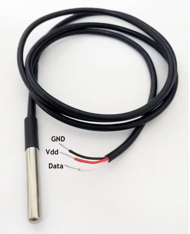
Introducing the DS18B20 sensor
The DS18B20 is a digital temperature sensor that communicates using the 1-Wire protocol, allowing data transfer over a single data line along with ground. This makes the sensor very easy to interface with microcontrollers while also supporting multiple devices on the same bus. The DS18B20 provides temperature measurements in degrees Celsius with a programmable resolution from 9-bit to 12-bit, enabling a balance between accuracy and conversion time based on application requirements.
Another important feature of the DS18B20 is its calibrated digital output, which eliminates the need for external ADCs or analog signal conditioning circuits. Each sensor comes with a unique 64-bit ROM address, making it possible to identify and read data from multiple sensors connected to the same data line. The sensor can be powered either through an external supply or using parasite power mode, reducing wiring complexity in compact designs.
Advantages
- Simple 1-Wire interface requiring minimal GPIO usage
- Accurate and reliable digital temperature measurements
- No external ADC or signal conditioning required
- Supports multiple sensors on a single data line
- Optional parasite power operation reduces hardware components
Applications
- Industrial and embedded temperature monitoring systems
- HVAC and climate control applications
- Environmental monitoring and data logging
- Weather stations and outdoor sensing
- Smart home and IoT-based temperature measurement systems
How does the DS18B20 communicate ?
Initialization
The image below shows the initialisation timing of the DS18B20.
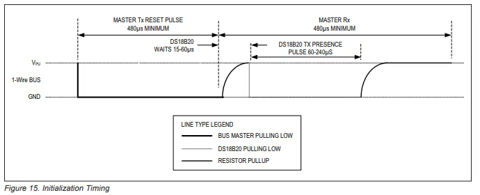
As show above, we need to pull the line LOW for around 480us and then release it. Then the sensor waits for around 60us and pull the line LOW for 60 – 240us to show its presence on the line.
Note:
You might need to connect pull-up resistance to the data line or else DS18B20 will not be able to pull it HIGH.
Write Timing
The images below shows the timing required to write a single bit to the sensor.
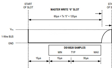
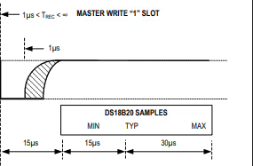
- To generate a Write 0 time slot, after pulling the line low, the master must continue to hold the line low for the duration of the time slot (at least 60µs).
- To generate a Write 1, after pulling the line low, the master must release the line within 15µs.
- When the bus is released, the 5kΩ pullup resistor will pull the bus high.
Read Timing
The image below shows the Timing to read a single bit from the sensor.
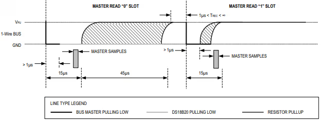
- A read time slot is initiated by the master device pulling the 1-Wire bus low for a minimum of 1µs and then releasing the bus.
- After the master initiates the read time slot, the DS18B20 will begin transmitting a 1 or 0 on bus.
- It transmits a 1 by leaving the bus high and transmits a 0 by pulling the bus low.
- When transmitting a 0, the sensor will release the bus by the end of the time slot, and the bus will be pulled back to its high idle state by the pull-up resister.
Wiring Diagram
The image below shows the connection between the sensor and the nucleo F446.
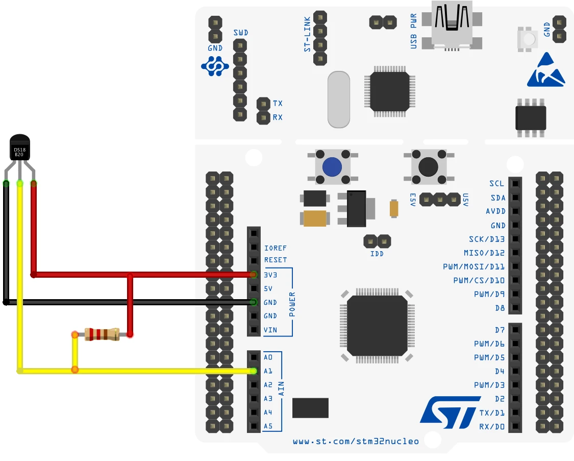
Since the DS18B20 only uses 1 wire to communicate to the MCU, I have connected it to the pin PA1. The sensor is powered with 3.3V from the nucleo board itself.
Note:
You might need to connect pull-up resistance to the data line or else DS18B20 will not be able to pull it HIGH.
STM32CubeMX Configuration
Clock configuration
The image below shows the clock configuration in the cubeMX.
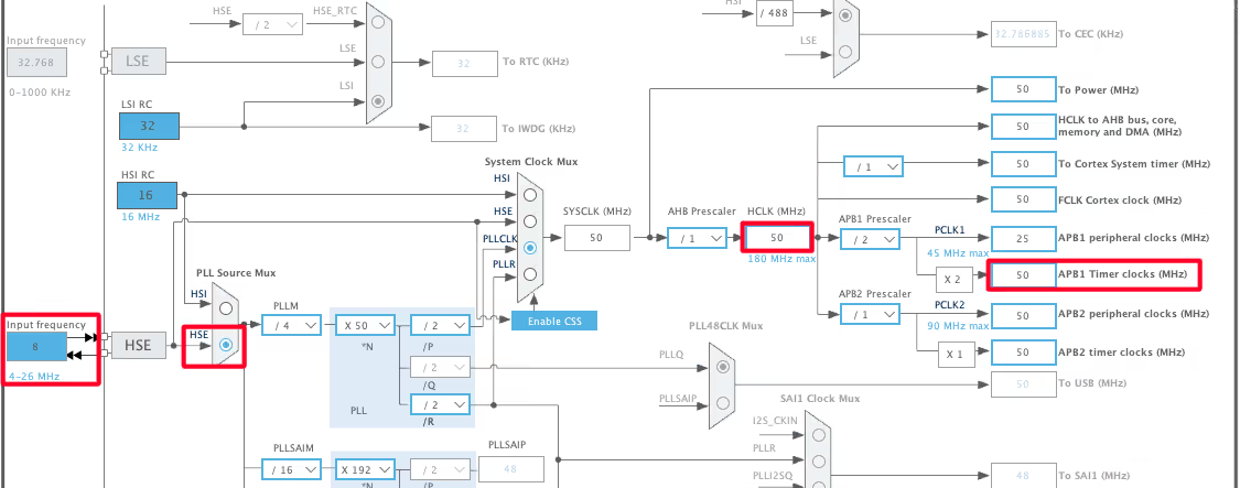
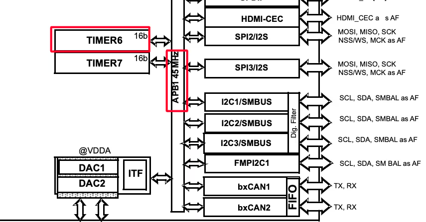
The system is clocked from the external 8MHz crystal and the HCLK is set to 50MHz. Note that the APB1 Timer clock is also at 50MHz. This is important because we will use the TIM6 to generate the delays in microseconds and the TIM6 is connected to the APB1 bus.
Timer Configuration
The image below shows the configuration of the TIM6.
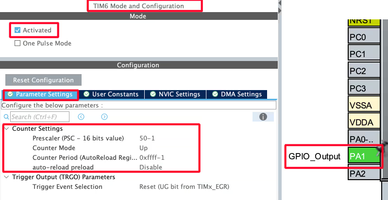
Since the APB1 Timer clock is at 50MHz, we will use the prescaler of 50 to bring the TIM6 clock to 1 MHz. This is already explained in the tutorial which explains how to generate the delays in micro/nanoseconds.
The pin PA1 is set as output, this is where the DS18B20 data pin is connected to.
I2C Configuration for LCD1602
We are using the LCD1602 to display the Temperature and Humidity data. The LCD is connected using the PCF8574 I2C extender. The image below shows the I2C configuration.
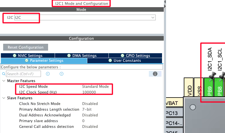
I am using the I2C1 to connect the LCD. The I2C is configured in the standard mode with the clock speed set to 100KHz. The pins PB8 and PB9 are configured as the SCL and SDA pins.
We have already covered how to interface the LCD via I2C with STM32. You can check out the tutorial for more details.
HAL Code to Interface DS18B20
Initialization
- Set the pin (data) as output.
- Pull the pin low and wait for 480us.
- set the pin as input for receiving the data.
uint8_t DS18B20_Start (void)
{
	uint8_t Response = 0;
	Set_Pin_Output(DS18B20_PORT, DS18B20_PIN);   // set the pin as output
	HAL_GPIO_WritePin (DS18B20_PORT, DS18B20_PIN, 0);  // pull the pin low
	delay (480);   // delay according to datasheet

Set_Pin_Input(DS18B20_PORT, DS18B20_PIN); // set the pin as input- wait for 80us.
- Check if the pin is pulled LOW by the sensor. If it is, then the sensor is responding fine with the presence pulse.
- Wait for another 400us, so to complete the entire timing of 480us.
        delay (80);    // delay according to datasheet
	if (!(HAL_GPIO_ReadPin (DS18B20_PORT, DS18B20_PIN))) Response = 1;    // if the pin is low i.e the presence pulse is detected
	else Response = -1;

	delay (400); // 480 us delay totally.

	return Response;
}Write Data
Below is the function to write a single byte to the sensor.
void DS18B20_Write (uint8_t data)
{
	Set_Pin_Output(DS18B20_PORT, DS18B20_PIN);  // set as output

	for (int i=0; i<8; i++)
	{
		if ((data & (1<<i))!=0)  // if the bit is high
		{
			// write 1
			Set_Pin_Output(DS18B20_PORT, DS18B20_PIN);  // set as output
			HAL_GPIO_WritePin (DS18B20_PORT, DS18B20_PIN, 0);  // pull the pin LOW
			delay (1);  // wait for 1 us

			Set_Pin_Input(DS18B20_PORT, DS18B20_PIN);  // set as input
			delay (50);  // wait for 60 us
		}

		else  // if the bit is low
		{
			// write 0
			Set_Pin_Output(DS18B20_PORT, DS18B20_PIN);
			HAL_GPIO_WritePin (DS18B20_PORT, DS18B20_PIN, 0);  // pull the pin LOW
			delay (50);  // wait for 60 us

			Set_Pin_Input(DS18B20_PORT, DS18B20_PIN);
		}
	}
}Here we will extract each bit from the data byte and check if it is a 1 or a 0. Then write the bit to the sensor.
The write timings for 1 and 0 are already explained above.
To write a 1, we will:
- Set the pin as output, pull it LOW and wait for 1us.
- Then release the pin immediately by setting it as input.
To write a 0, we will:
- Set the pin as output, pull it LOW and wait for 50us.
- Then release the pin by setting it as input.
Read Data
Below is the function to Read a data byte from the sensor.
uint8_t read (void)
{
	uint8_t value=0;
	gpio_set_input ();

	for (int i=0;i<8;i++)
	{
		gpio_set_output ();   // set as output
		HAL_GPIO_WritePin (GPIOA, GPIO_PIN_1, 0);  // pull the data pin LOW
		delay (2);  // wait for 2 us
		gpio_set_input ();  // set as input
		if (HAL_GPIO_ReadPin (GPIOA, GPIO_PIN_1))  // if the pin is HIGH
		{
			value |= 1<<i;  // read = 1
		}
		delay (60);  // wait for 60 us
	}
	return value;
}I have already explained the Read timings in the beginning of this tutorial. Basically we need to pull the pin low for >1us and then release it. Now we will check the state of the pin.
- If the pin is HIGH, that means the sensor did not pulled it low, so the bit is a 0.
- If the pin is LOW, the sensor must have pulled it LOW, so the bit is a 1.
Then combine all the bits received to make a single byte.
The Main Function
Inside the main function, we will continuously read the temperature after a particular interval. This is why the code is inside the while loop.
int main ()
{
  ...
  ...
  while (1)
  {
     Presence = DS18B20_Start ();
     DS18B20_Write (0xCC);  // skip ROM
     DS18B20_Write (0x44);  // convert t

     Presence = DS18B20_Start ();
     DS18B20_Write (0xCC);  // skip ROM
     DS18B20_Write (0xBE);  // Read Scratch-pad

     Temp_byte1 = DS18B20_Read();
     Temp_byte2 = DS18B20_Read();
     TEMP = ((Temp_byte2<<8))|Temp_byte1;
     Temperature = (float)TEMP/16.0;  // resolution is 0.0625

     HAL_Delay(3000);
     Display_Temp(Temperature);
  }
}We will read the data as according to the information given in the datasheet.
- Basically the master will send the reset sequence and detect the presence pulse. Then it will issue the skip rom command followed by the convert t command.
- It will again send the reset condition and read the presence pulse. It will then send the skip rom command followed by the read scratchpad command.
- Then the master will request 2 bytes data from the sensor. It will first read the Least Significant Byte followed by the Most Significant Byte of the temperature data.
- The sensor is configured with 12 bit resolution by default. Hence we will have a total of 12 bits of the data. The 2 bytes of the temperature data will be combined to form a single 12 bit data.
- With the resolution of 12 bit, the temperature is set to 0.0625 °C per bit value. Hence to convert the 12 bit temperature data to actual temperature, we will multiply the 12 bit value with 0.0625 or divide by 16.
Since we are also displaying the data on the LCD, the LCD is initialised in the main function itself. We have already covered how to use the LCD1602 via I2C to display strings, numbers, floats etc. Below are the functions for displaying the data on the LCD.
void Display_Temp (float Temp)
{
	char str[20] = {0};
	lcd_put_cur(0, 0);
	sprintf (str, "TEMP:- %.2f ", Temp);
	lcd_send_string(str);
	lcd_send_data('C');
}Result on the LCD1602
Below is the image showing the output temperature data on the LCD.
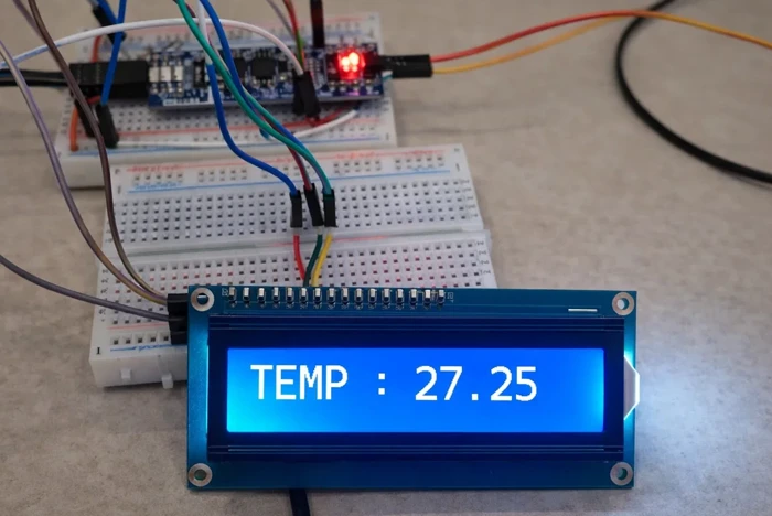
The image shows the temperature value (27.25 °C) displayed on the LCD1602, confirming successful communication between the DS18B20 sensor and the STM32 microcontroller.
VIDEO TUTORIAL
STM32 DS18B20 Temperature Sensor Tutorial Video
This tutorial demonstrates how to interface the DS18B20 digital temperature sensor with an STM32 microcontroller using STM32CubeIDE and HAL libraries. You’ll see how the 1-Wire communication protocol works, how to generate precise microsecond delays using a timer, perform reset and presence detection, read temperature data from the sensor, and convert it into a readable format. A complete video walkthrough is included to clearly show the timing-critical communication and temperature reading process. Follow the written guide along with the video for a better understanding of the implementation.
Watch the VideoConclusion
In this tutorial, we covered how to interface the DS18B20 digital temperature sensor with an STM32 microcontroller using STM32CubeIDE and HAL libraries. We discussed the working of the 1-Wire protocol, including reset and presence detection, read and write timing, and how to generate accurate microsecond delays using a timer. The tutorial also demonstrated how to read raw temperature data from the sensor, convert it into a human-readable format, and display the result on an LCD1602.
This approach provides a simple and reliable way to measure temperature in embedded systems with minimal hardware requirements. Due to its accuracy, digital output, and ability to support multiple sensors on a single data line, the DS18B20 is well suited for a wide range of applications such as environmental monitoring, industrial control, and smart embedded projects. The concepts covered in this tutorial can be easily adapted to other STM32 boards and extended for more advanced temperature-based applications.
You can check out some other tutorials related to this post:
- Multiple DS18B20 using UART
- One-Wire Protocol using UART
- Interface the DHT11 sensor with STM32
- Interface DHT22 sensor with STM32
Checkout More STM32 Sensors Tutorials
How to interface HCSR04 sensor with STM32
Interface AHT20 Sensor with STM32 Using I2C
Interfacing ADXL345 Accelerometer with STM32 via I2C
GP2Y0A41SK0F STM32 ADC Distance Measurement Guide
How to Interface DHT11 Temperature and Humidity Sensor with STM32 using HAL

How to interface MPU6050 (GY-521) with STM32
Interface BMP180 with STM32
STM32 DS18B20 Project Download
STM32 DS18B20 FAQs


Can this code also read negative temperatures?
Sensor keeps sending -127 degress. meaning it keeps reading ‘1’ any ideas how this might happen?
Main:
if (Presence == 1) {
DS18B20_Write(0xCC); // Skip ROM (address all devices)
DS18B20_Write(0x44); // Start temperature conversion
// Wait until conversion is complete (max 750ms for 12-bit resolution)
HAL_Delay(750);
// Reset again and check presence before reading scratchpad
Presence = DS18B20_Start();
if (Presence == 1) {
DS18B20_Write(0xCC); // Skip ROM
DS18B20_Write(0xBE); // Read Scratchpad command
// Read all 9 bytes from the scratchpad (bytes 0-7: data, byte 8: CRC)
for (int i = 0; i < 9; i++) {
scratchpad[i] = DS18B20_Read();
}
// Calculate CRC of first 8 bytes and compare with the 9th byte
uint8_t calcCRC = DS18B20_CRC8(scratchpad, 8);
if (calcCRC == scratchpad[8]) {
// CRC is valid – use the temperature data
Temp_byte1 = scratchpad[0];
Temp_byte2 = scratchpad[1];
TEMP = (Temp_byte2 << 8) | Temp_byte1; // Combine LSB and MSB
Temperature = (float)TEMP / 16.0f; // Convert raw value to Celsius (each unit = 0.0625°C)
// DEBUG: Valid temperature reading stored in Temperature
// (Use Temperature value as needed, e.g., display on LCD or save for later transmission)
} else {
// CRC invalid – ignore this reading
// DEBUG: CRC check failed, temperature reading discarded
}
} else {
// DEBUG: DS18B20 not present during scratchpad read
}
} else {
// DEBUG: DS18B20 not responding to reset (sensor missing or fault)
}
Other functions:
void delay(uint16_t us)
{
__HAL_TIM_SET_COUNTER(&htim2,0); // set the counter value a 0
while (__HAL_TIM_GET_COUNTER(&htim2) < us); // wait for the counter to reach the us input in the parameter
}
void Set_Pin_Output (GPIO_TypeDef *GPIOx, uint16_t GPIO_Pin)
{
GPIO_InitTypeDef GPIO_InitStruct = {0};
GPIO_InitStruct.Pin = GPIO_Pin;
GPIO_InitStruct.Mode = GPIO_MODE_OUTPUT_PP;
GPIO_InitStruct.Speed = GPIO_SPEED_FREQ_LOW;
HAL_GPIO_Init(GPIOx, &GPIO_InitStruct);
}
void Set_Pin_Input (GPIO_TypeDef *GPIOx, uint16_t GPIO_Pin)
{
GPIO_InitTypeDef GPIO_InitStruct = {0};
GPIO_InitStruct.Pin = GPIO_Pin;
GPIO_InitStruct.Mode = GPIO_MODE_INPUT;
GPIO_InitStruct.Pull = GPIO_PULLUP;
HAL_GPIO_Init(GPIOx, &GPIO_InitStruct);
}
uint8_t DS18B20_Start (void){
uint8_t Response = 0;
Set_Pin_Output(DS18B20_PORT, DS18B20_PIN); // set the pin as output
HAL_GPIO_WritePin (DS18B20_PORT, DS18B20_PIN, 0); // pull the pin low
delay(480); // delay according to datasheet
Set_Pin_Input(DS18B20_PORT, DS18B20_PIN); // set the pin as input
delay(80); // delay according to datasheet
if (!(HAL_GPIO_ReadPin (DS18B20_PORT, DS18B20_PIN))) Response = 1; // if the pin is low i.e the presence pulse is detected
else Response = -1;
delay(400); // 480 us delay totally.
return Response;
}
void DS18B20_Write (uint8_t data){
Set_Pin_Output(DS18B20_PORT, DS18B20_PIN); // set as output
for (int i=0; i<8; i++)
{
if ((data & (1<<i))!=0) // if the bit is high
{
// write 1
Set_Pin_Output(DS18B20_PORT, DS18B20_PIN); // set as output
HAL_GPIO_WritePin (DS18B20_PORT, DS18B20_PIN, 0); // pull the pin LOW
delay (5); // wait for 1 us
Set_Pin_Input(DS18B20_PORT, DS18B20_PIN); // set as input
delay (60); // wait for 60 us
}
else // if the bit is low
{
// write 0
Set_Pin_Output(DS18B20_PORT, DS18B20_PIN);
HAL_GPIO_WritePin (DS18B20_PORT, DS18B20_PIN, 0); // pull the pin LOW
delay (60); // wait for 60 us
Set_Pin_Input(DS18B20_PORT, DS18B20_PIN);
}
}
}
uint8_t DS18B20_Read (void)
{
uint8_t value=0;
Set_Pin_Input(DS18B20_PORT, DS18B20_PIN);
for (int i=0;i<8;i++)
{
Set_Pin_Output (DS18B20_PORT, DS18B20_PIN); // set as output
HAL_GPIO_WritePin (DS18B20_PORT, DS18B20_PIN, 0); // pull the data pin LOW
delay (5); // wait for 2 us
Set_Pin_Input (DS18B20_PORT, DS18B20_PIN); // set as input
delay (15);
if (HAL_GPIO_ReadPin (DS18B20_PORT, DS18B20_PIN)){ // if the pin is HIGH
value |= 1<<i; // read = 1
}
delay (40); // wait for 60 us
}
return value;
}
// Static CRC-8 calculation for Dallas/Maxim (DS18B20) – polynomial x^8 + x^5 + x^4 + 1 (0x31)
static uint8_t DS18B20_CRC8(const uint8_t *data, uint8_t len) {
uint8_t crc = 0;
while (len–) {
uint8_t byte = *data++;
for (uint8_t i = 0; i < 8; i++) {
uint8_t mix = (crc ^ byte) & 0x01;
crc >>= 1;
if (mix) {
crc ^= 0x8C; // 0x8C is the reversed polynomial 0x31
}
byte >>= 1;
}
}
return crc;
}
Why do i get temperature = 0 ?
Hi!
I have a project and using several Task in RTOS.
One of the task is DS18B20 Driver Code that use above Code.
When DS18B20 not connect to stm32, the another task dont run.
Can you help me?
Maybe the blocking mode is an issue. Try using this one https://controllerstech.com/multiple-ds18b20-sensors-using-uart/
why i have error:
conflicting types for ‘DS18B20_Start’
check if you are using some other library also… There is no way there can be a conflicting types, as it is only defined once.
Где узнать про ds18b20 stm32
Thank you a lot for your effort 🙂 I have a problem. I am using STM32L031K6T6. Your function “SetInput” and “Set Output” took me 40us each. so there is no possibility to wait only 1 us. Can you please give me an advice? thanks
hi, thanks for the code. But it cant read negative temperature values so how I need to modify the code to also do that.
Hello
I tried to connect DS2431 eeprom according to your explanations. It looks like very similar . But i could not read or write it. we will be grateful if you use DS2431 eeprom in your next videos . Thanks for your supports .
Can you do same video with more sensor ds18b20, for example 4 or 5 (like example 1 in datasheet )?
Hi,
Thanks for you code… I used to get a faster result.
But I needed to correct few things…
This is my version which could help someone surfing here ^^
Context : NRF52 (ARM cortex M3) and some custom functions for delays… I’m pretty confident it can work on STM32, with few changes in the macos.
————-
/*
* DS18B20.c
*
* Created on: 3 mai 2021
* Author: Nirgal
*/
#include “../appli/config.h”
#if USE_DS18B20
#include “../appli/common/systick.h”
#include “../appli/common/gpio.h”
#ifndef DS18B20_PIN
#define DS18B20_PIN (13)
#endif
#define DS18B20_delay_us SYSTICK_delay_us
#define DS18B20_delay_ms SYSTICK_delay_ms
#define DS18B20_pin_write(x) GPIO_write(DS18B20_PIN, x);
#define DS18B20_pin_read() GPIO_read(DS18B20_PIN)
static volatile bool_e initialized = FALSE;
static uint8_t DS18B20_Start (void);
static void DS18B20_Write (uint8_t data);
static uint8_t DS18B20_Read (void);
void DS18B20_init(void)
{
if(!initialized)
{
GPIO_configure_input_output_opendrain(DS18B20_PIN, GPIO_PIN_CNF_PULL_Pullup); // set the pin as output opendrain
initialized = TRUE;
}
}
int16_t DS18B20_get_temperature(void)
{
uint8_t msb, lsb;
msb = 0;
lsb = 0;
uint8_t presence;
if(!initialized)
DS18B20_init();
presence = DS18B20_Start();
if(presence)
{
SYSTICK_delay_us(1000);
DS18B20_Write (0xCC); // skip ROM
DS18B20_Write (0x44); // convert t
DS18B20_delay_ms(800);
presence = DS18B20_Start();
if(presence)
{
DS18B20_delay_us(1000);
DS18B20_Write (0xCC); // skip ROM
DS18B20_Write (0xBE); // Read Scratch-pad
msb = DS18B20_Read();
lsb = DS18B20_Read();
}
}
return U16FROMU8(msb, lsb);
}
static uint8_t DS18B20_Start (void)
{
uint8_t response = 0;
DS18B20_pin_write(0); // pull the pin low
DS18B20_delay_us(480); // delay according to datasheet
DS18B20_pin_write(1);
DS18B20_delay_us(80); // delay according to datasheet
if (!(GPIO_read(DS18B20_PIN)))
response = 1; // if the pin is low i.e the presence pulse is detected
DS18B20_delay_us(400); // 480 us delay totally.
return response;
}
static void DS18B20_Write (uint8_t data)
{
for(int i=0; i<8; i++)
{
if((data & (1<<i))!=0) // if the bit is high
{ // write 1
DS18B20_pin_write(0); // pull the pin LOW
DS18B20_delay_us(1); // wait for 1 us
DS18B20_pin_write(1);
DS18B20_delay_us(60); // wait for 60 us
}
else // if the bit is low
{ // write 0
DS18B20_pin_write(0);
DS18B20_delay_us(60); // wait for 60 us
DS18B20_pin_write(1);
DS18B20_delay_us(15); //wait for pull up !
}
}
}
static uint8_t DS18B20_Read (void)
{
uint8_t value=0;
for(int i=0;i<8;i++)
{
DS18B20_pin_write(0); // pull the data pin LOW
DS18B20_delay_us(2); // wait for 2 us
DS18B20_pin_write(1); // set as input
DS18B20_delay_us(10); // wait for pullup if the sensor do not write 0
if(DS18B20_pin_read()) // if the pin is HIGH
{
value |= 1<<i; // read = 1
}
DS18B20_delay_us(50); // wait for the remaining 50 us (50+10 = 60)
}
return value;
}
#endif
Sorry about inverting lsb & msb in this code…
You should read in this order:
lsb = DS18B20_Read();
msb = DS18B20_Read();
and if you want display the result:
int16_t temperature = DS18B20_get_temperature();
printf(“%d.%04d°C\n”,temperature/16, 625*(temperature%16));
hi nirgal, thanks for your code, and can you give me the code of functions DS18b20_delay_us(50)?? many thanks
Gracias amigo, saludos desde mi amada Venezuela.
Thanks friend, greetings from my beloved Venezuela.
öncelikle merhaba indirdiğim kodu açamıyorum yardımcı olur musunuz.
why temper=tem/16
because the sensitivity is .0625 per bit. please check the datasheet
Please, seeng this example, I tried implement for multiple sensors but I can’t to do this, anybody can help me
Hi, I used the code as instructed, no errors no warnings, i m using stm32f407 discovery board. But no response, the temperature isn’t appearing (in the debug mode, i didn’t use LCD). I enabled tim1 ( APB2= 100 MHZ, prescaler= 100-1, and period= 0xffff-1). And in the main I used the function ( HAL_TIM_BASE_START(&htim).
It should work alright. Debug the code, and check where the execution is stuck.
i update the delay function too:
void Delay (uint_16 us)
{
HAL_TIM_BASE_Start(&htim1);
__HAL_TIM_SET_COUNTER(&htim1,0);
while ((__HAL_TIM_GET_COUNTER(&htim1))<us);
HAL_TIM_BASE_Stop(&htim1);
}
and the counter period to 1.
t=(100-1/100000000)*1.
the same no response.
there is no debug execution stuck . i put many break points, and the code run well and stops at the break points. but no temperature value.
Have you connected the pull up resistor to the data pin ?
I would like to see the code.
Mail me [email protected]
Or telegram @controllerstech
I really appreciate what you are doing ..when I’m watching youtube tutorial and hear background music which is exclusive for your tutorial ..it makes me cheerfull ..because I am sure that it is going to work out..thanks for that, keep it on I learn a lot from you.
Hi, thx for good projekt. Can you say me , how does work read function by Value? I have Problem with value |= 1<<i.
Value must be OR with (1<< i) and i must schift 1 bit to Right ?
THX
We are reading the pin and if the pin is HIGH, we are shifting ‘1’ to that place.
I would like to know how do I use more than one sensor on the same pin with these functions?
I will work on it soon.
hello admin !
did you something about more than one sensor ?
thanks
very good the text. I would like to know how to read more than one sensor on the same pin? That is possible with this code ?
up
Hi!! I like very very much your tutorials, thank you very much!!
It would be nice to have the correct source files for the ds18b20, as they are for i2c lcd. Could you, please, provide the files accordingly?
Many thanks and best regards!!
Luiz
sure will do that in future tutorial
Hi!
This description very good, need attention read all material.
Simple code and algorithm usability peripheries, me like this site 🙂
Good Luck!