Home ▸ STM32 Tutorials ▸
Updated On: June 20, 2026
How to configure the FMC peripheral to interface the LCD
The FSMC stands for Flexible Static Memory Controller and as the name suggests, this peripheral is used for interfacing different types of external memories with the STM32 MCU. The FSMC can be used to Interface static-memory mapped devices including:
- Static random access memory (SRAM)
- NOR Flash memory/One NAND Flash memory
- PSRAM (4 memory banks)
Not only memories but we can also use it to Interface the parallel LCD modules, supporting Intel 8080 and Motorola 6800 modes.
In this tutorial about the FSMC peripheral, we will focus on interfacing the LCD. The 8 bit or 16 bit parallel LCD modules are supported by the FSMC peripheral. I am using the STM32F412 Discovery board for this tutorial. The LCD comes pre attached to the board and it is connected via the FSMC.
VIDEO TUTORIAL
You can check the video to see the complete explanation and working of this project.
Connection
As I mentioned, the LCD comes pre attached to the board. Below is the schematics of the LCD.
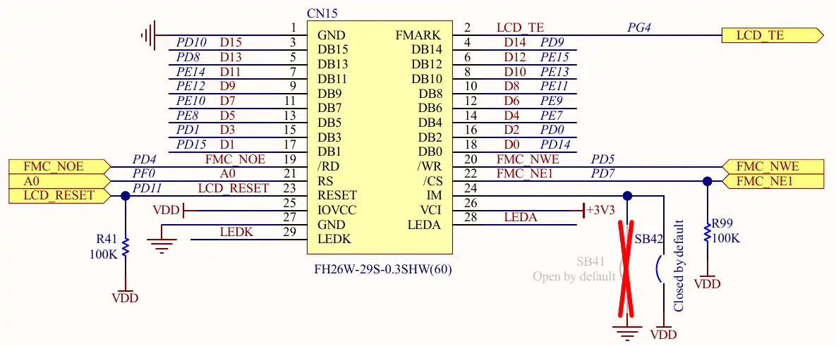
If you are connecting an external LCD, you are free to choose the Chip Select (NE1 in this case) and the Register Select (A0 in this case). However any changes in these parameters would change the code. You are advise to check the Register Select and the Chip Select part carefully.
Along with the connection shown above, the LCD Backlight Control is connected to the PF5 of the MCU.
The cubeMX is setup according to this configuration. The 16 data pins are configured as per the image shown above. The configuration for the rest of the pins is shown in the image below.
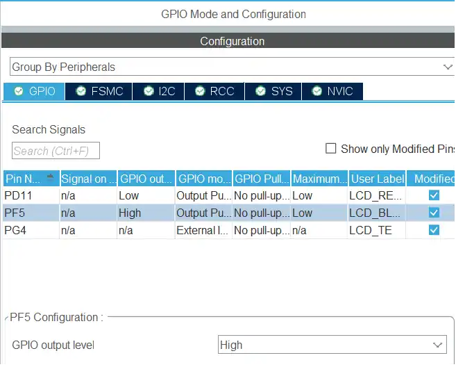
- The PD11 is the LCD RESET pin. It is kept LOW in the beginning, we will modify it later in the code.
- The PF5 is connected to the LCD Backlight Control. This pin is set to HIGH so to enable the LCD backlight.
- The pin PG4 is connected to the LCD Tearing Effect. This pin is set in the external interrupt mode.
CubeMX Configuration
Below is the configuration shown for the FSMC peripheral.
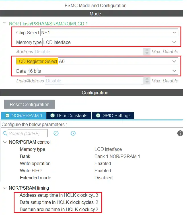
The chip select is set to NE1, because this is how the LCD is connected to the FMC. You can check the connection diagram shown above. The Memory type is LCD Interface.
The LCD Register select is set to A0 as according to the connection diagram. The Register select is used to select between the command and data sent to the LCD. We will cover this parameter in depth later in the tutorial.
The Data width is set to 16 bits as the LCD is connected using 16 data pins.
The NOR/PSRAM control is kept to default configuration, but we need to configure the timing manually.
As per the Application Note AN2784, below are the formulas to calculate the Address and Data setup Time.

The values twp, twc and trc can be found in the LCD datasheet. Below is the image from the ST7789H2 datasheet.
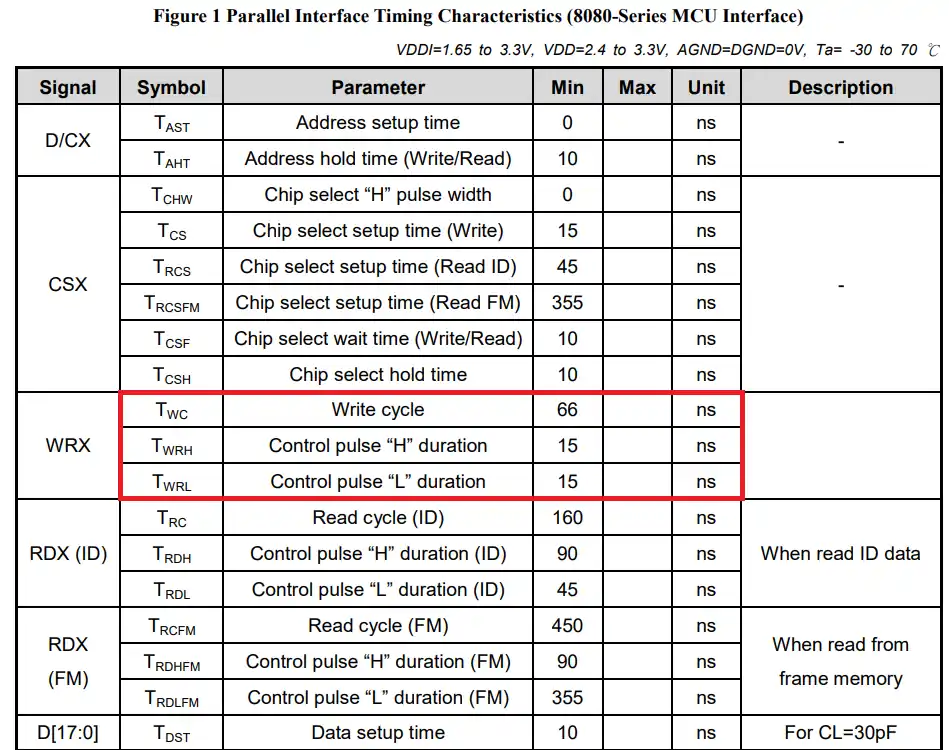
The twp stands for Write Enable low to Write Enable high, but we don’t have such value in the ST7789H2 datasheet. So to calculate the Data setup time, I will use the average of Twrh and Twrl. The HCLK is at 100MHz, so the tHCLK (clock cycle) = 1/100MHz = 10ns.
Using the above formula, we have the DATAST value equal to 2 and ADDSET value equal to 3. There is no formula to calculate the Bus turn around time, so I am just setting it to 2.
The Code
I got the Library for the ST7789H2 from the ST’s database. You can get it inside the STM32Cube folder in your computer at STM32Cube\Repository\STM32Cube_FW_F4_V1.28.0\Drivers\BSP\Components\st7789h2.
There are other LCD libraries available inside these folders as well. But all these libraries do not include functions to connect the display to the MCU. We need to define those functions ourselves and their code will change based on how the display is connected to the MCU. We can write the functions in terms of I2C, SPI, FMC, or even using the normal GPIO operations.
Below is the image showing the functions needed to be defined. The functions are defined as the external functions in the ST7789H2 header file and they will be used to connect the display to the MCU.
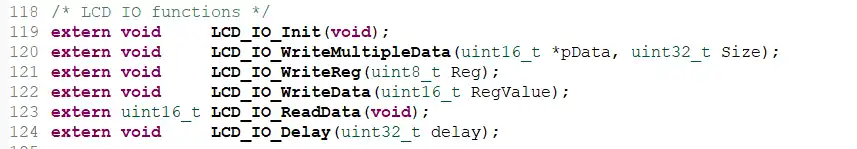
We will create new source an header files to define these functions separately. I am naming the files as LCD_Controller.c and LCD_Controller.h.
LCD Controller
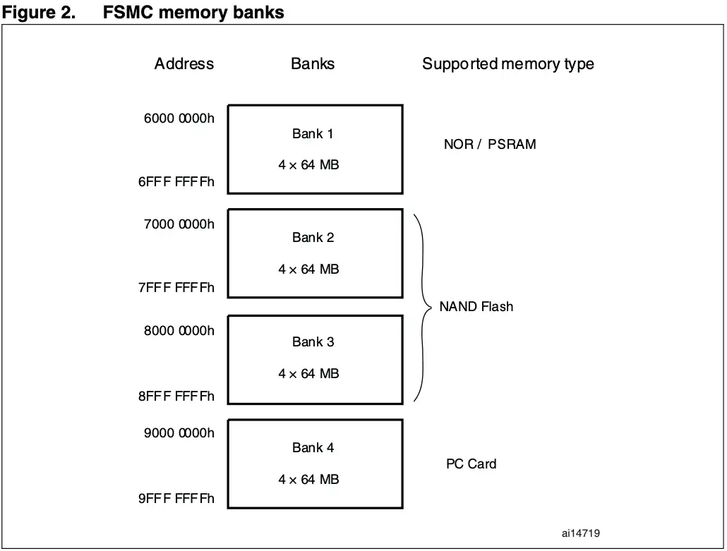
We will first define the FMC bank addresses for storing the command and data values. Below is the definition of these addresses.
#define FMC_BANK1_REG  ((uint16_t *) 0x60000000)  // Register Address for A0
#define FMC_BANK1_DATA ((uint16_t *) 0x60000002) // Data Address for A0 -> A0<<1 -> 0010The FSMC NOR/PSRAM bank address starts from 0x60000000.
The Register Select is set to A0. The addresses of the command and data are based on this value. Below is the image explaining how this works.
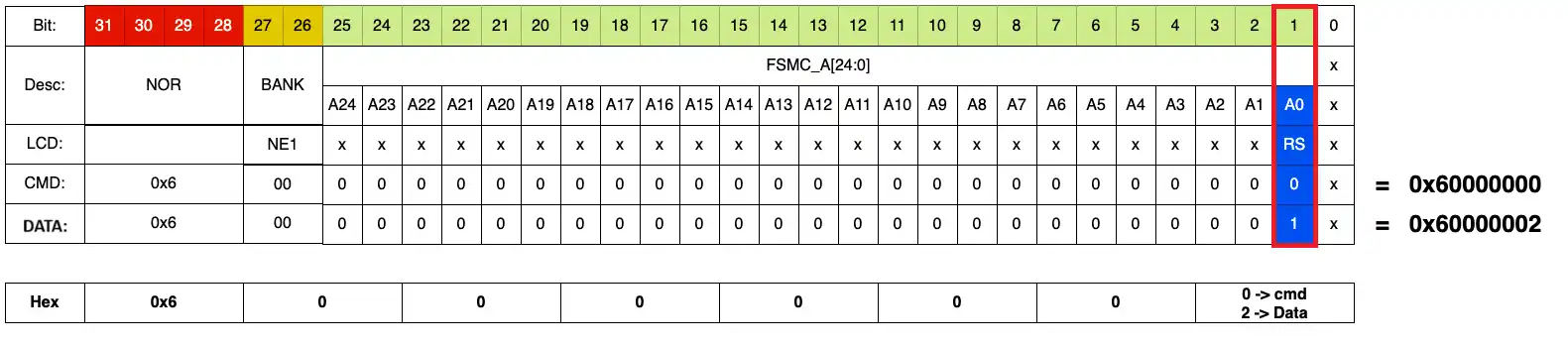
While using 16 bit data width, the AHB Address line does not consider the bit 0 and start the bit counting from 1. The total bits available for 16 bit data width ranges from 1 to 25. The AHB Address line then shifts this data to the right by 1 position HADDR[25:1]>>1.
Therefore if the Register Select is set to A0, the RS bit will be considered at the position 1, basically at the offset of 2 (0010). Similarly, if the Register Select is set to A4, RS bit will be considered at the position 5, basically at an offset of 32 (0010 0000).
This only applies to the 16 bit data width. If the LCD is connected with 8 data lines, the bit 0 is considered and the data address starts from the position 0 itself.
In case of 8 bit data width, if the Register Select is set to A4, RS bit will be considered at the position 0, at an offset of 16 (0001 0000) as shown below.
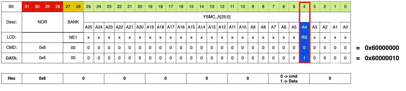
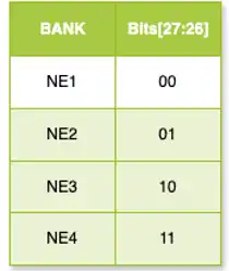
The bits HADDR[27:26] are used for the configuring the chip select. These bits can be used to switch from NE1 to NE4.
Now we have the memory locations for the storing the command and address so let’s write the rest of the code.
void LCD_IO_WriteReg(uint8_t Reg)
{
	*FMC_BANK1_REG = Reg;
}

void LCD_IO_WriteData(uint16_t RegValue)
{
	*FMC_BANK1_DATA = RegValue;
}- The function LCD_IO_WriteReg is used to send the register address to the LCD. We will simply copy it to the Register memory location.
- The function LCD_IO_WriteData is used to send the register value to the LCD. We will copy it to the Data memory location.
void LCD_IO_WriteMultipleData(uint16_t *pData, uint32_t Size)
{
	for (uint32_t i=0; i<Size; i++)
	{
		LCD_IO_WriteData(pData[i]);
	}
}The function LCD_IO_WriteMultipleData is used to send multiple data bytes to the LCD. Here we will simply call the function LCD_IO_WriteData as many times as we have the size of the data bytes.
uint16_t LCD_IO_ReadData(void)
{
	return *FMC_BANK1_DATA;
}The function LCD_IO_ReadData is used to read the data from the memory. Here we will return the data from the Data location.
void LCD_IO_Delay(uint32_t delay)
{
	HAL_Delay(delay);
}

void  LCD_IO_Init(void)
{
	HAL_GPIO_WritePin(LCD_RESET_GPIO_Port, LCD_RESET_Pin, GPIO_PIN_RESET);
	LCD_IO_Delay(5);   /* Reset signal asserted during 5ms  */
	HAL_GPIO_WritePin(LCD_RESET_GPIO_Port, LCD_RESET_Pin, GPIO_PIN_SET);
	LCD_IO_Delay(10);  /* Reset signal released during 10ms */
}The function LCD_IO_Delay is used as the delay function by the LCD. Here we will simply call the HAL_Delay and pass the parameter to it.
The function LCD_IO_Init is used to initialize the display. Here we will first Reset the LCD and then Set it again after some delay.
Main function
To test the display we will fill it with some colors. The ST7789H2 does not have a function to fill the display, so we will define a function in the main file.
void LCD_Fill(uint16_t RGBCode, uint16_t Xpos, uint16_t Ypos, uint16_t width, uint16_t height)
{
	for (uint16_t i=0; i<height; i++)
	{
		ST7789H2_DrawHLine(RGBCode, Xpos, Ypos++, width);
	}
}This function will simply utilize another function, which draws horizontal line of the given color. This function will be called for the entire height so to fill the entire screen with the color.
  ST7789H2_Init();

  while (1)
  {
	  LCD_Fill(0xF800, 0, 0, 240, 240);
	  HAL_Delay(1000);
	  LCD_Fill(0x07E0, 0, 0, 240, 240);
	  HAL_Delay(1000);
	  LCD_Fill(0x001F, 0, 0, 240, 240);
	  HAL_Delay(1000);
	  LCD_Fill(0xFFE0, 0, 0, 240, 240);
	  HAL_Delay(1000);
}Inside the main function, we will initialize the LCD first. Then in the while loop fill the LCD with a specific color every 1 second.
Result
Below is the gif showing the LCD displaying different colors every 1 second.

STM32 FSMC Tutorial Series
STM32 FMC || LCD PART2 || How to add touch interface to the LCD
STM32 FMC || LCD PART3 || Add LVGL & Create UI
LVGL on STM32 || PART 6


awesome
many thanks! very clear explanation…