
Home ▸ STM32 Tutorials ▸
Updated On: March 23, 2026
How to create the SPI Flash loader
This is the 9th tutorial in the W25Q Flash series, and today we will see how to create and use the External Loader for the W25Q flash memory with the SPI peripheral. In the previous tutorial we saw how to create an external loader using QSPI peripheral. Today’s tutorial is going to be somewhat similar, but we will use the SPI peripheral instead of the QSPI.
Using the QSPI peripheral for external flash memories have major advantages like faster speed, memory mapped mode, etc. But we know that not all the STM32 MCUs supports the QSPI mode, specially the popular and cheaper dev boards like F4 discovery, bluepill, F4 nucleo etc. Using SPI flash loader, we can still use the W25Q flash memories to store the data to the external flash using the SPI peripheral.
With SPI flash loader, we can use the cube programmer to flash the binary file to the external flash memory, which can contain data like images or fonts. The data can later be read in the IDE itself. Although we can not use the memory mapped mode, so the internal flash is not extended in a way.
The process of creating the external loader will be the same as we did in the previous QSPI tutorial. Although I have made some changes in the files used and I will explain those changes here.
VIDEO TUTORIAL
You can check the video to see the complete explanation and working of this project.
Connection
The connection diagram between the Flash module and the STM32 is shown below.
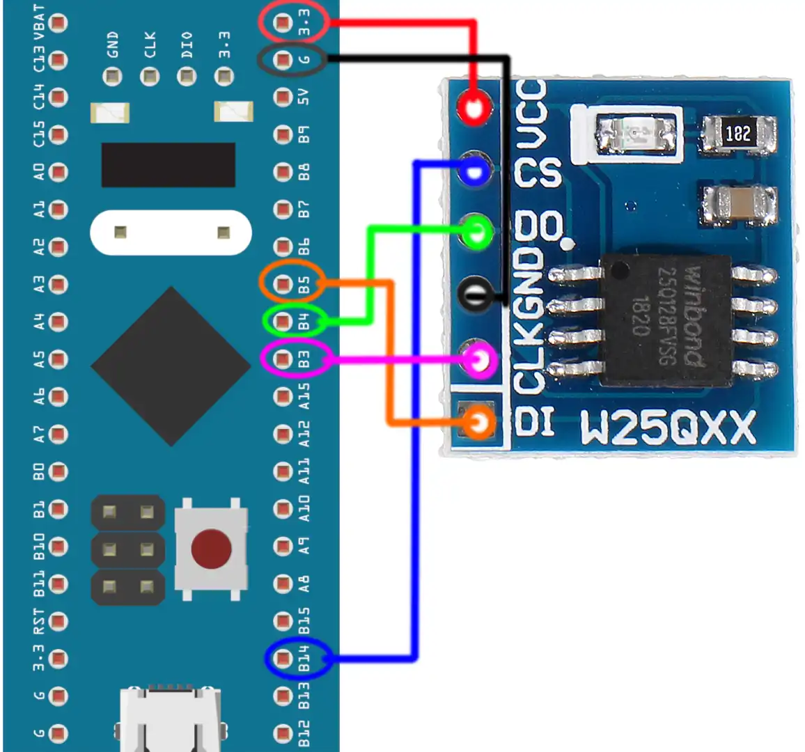
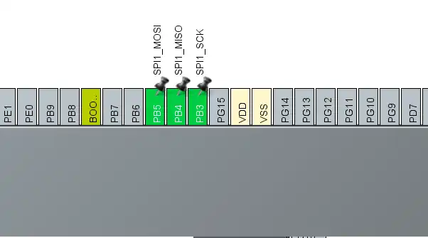
- The CS (Chip Select) Pin is connected to the pin PB14. It will be used to select or unselect the slave Device.
- The DO (Data Out) pin is connected to the pin PB4 (MISO). The device outputs the data on this pin
- The CLK (Clock) pin is connected to the pin PB3 (CLK). The clock is used to synchronise the master and the slave device.
- The DI (Data In) pin is connected to the pin PB5 (MOSI). The master send the data to the device on this pin.
- The Device is powered with 3.3v from the MCU itself.
The Module provides 6 pins (including the Vcc and Gnd). But the chip has 8 pins in total. If you have the chip rather than the module, you can connect it as shown below.
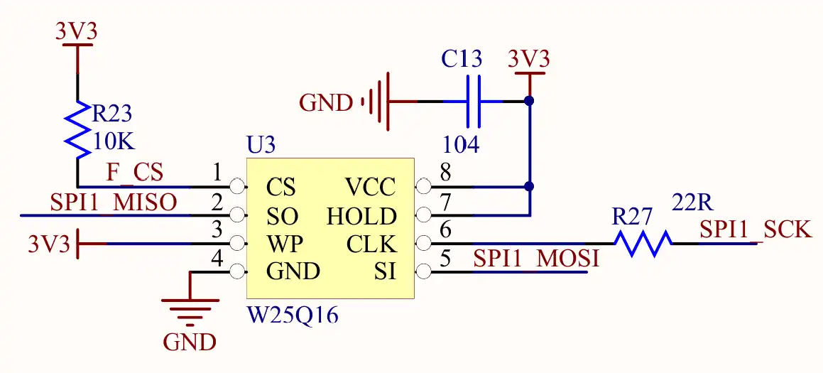
Note that the WP (Write Protect) pin is active Low pin, so it must be pulled HIGH when you want to modify the flash, and pulled LOW when you want to disable the modification.
The connections shown above are for the Single SPI mode, not for Dual or Quad modes.
CubeMX Setup
We will enable the SPI in Full Duplex master mode. The configuration is shown below.
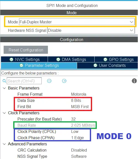
The Data width is set to 8 bits and the data should be transferred as the MSB first. The prescaler is set such that the Baud Rate is around 2.5 Mbits/sec.
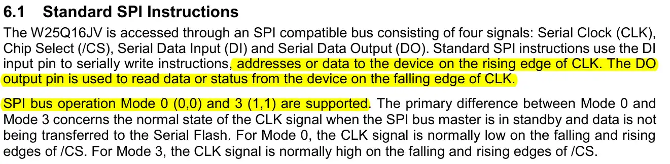
According to the datasheet of the W25Q Flash, the SPI Mode 0 and Mode 3 are supported. Below is the image from the datasheet.
In the SPI configuration, we keep the Clock Polarity (CPOL) low and the Clock Phase (CPHA) to 1 edge. Here 1 edge means that the data will be sampled on the first edge of the clock. And when the CPOL is Low, the first edge is the rising edge. Basically we are using the SPI Mode 0.
In Full duplex Mode, SPI uses 3 pins, MOSI, MISO and CLK. We need to set one more pin as output so to be used as the Chip Select (CS) Pin.
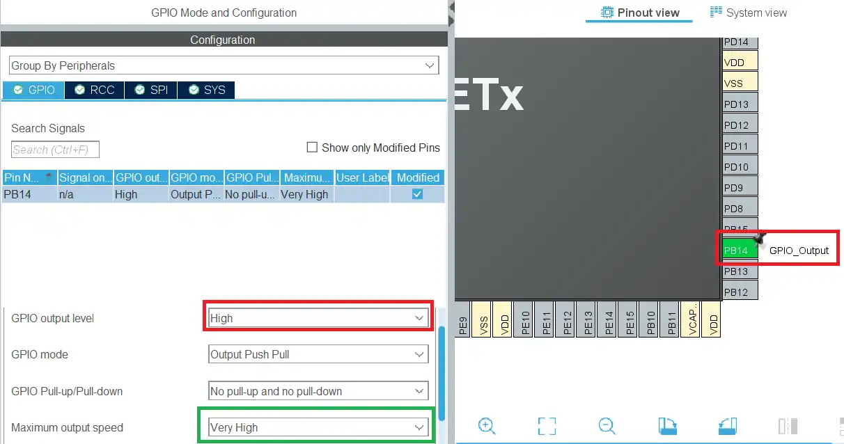
The Pin PB14 is set as the CS pin. The initial output level is set to HIGH. This is because the pin needs to be pulled low in order to select the slave device, so we keep it high initially to make sure the slave device isn’t selected. The Output speed is set to Very High because we might need to select and unselect the slave at higher rate.
Create the Loader
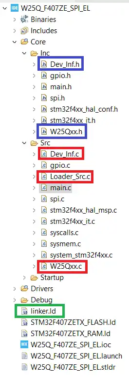
We need to first copy certain files into our project. You can get the files after downloading the project at the end of this post.
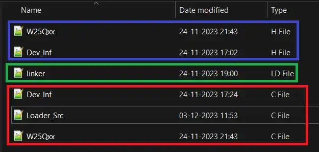
Now copy the ***.c files in the src directory of the project, ***.h file in the inc directory and the linker file in the main project folder. The final project structure is shown below.
You can set the Loader name in the Dev_inf.c file as shown below. Also make sure to cross check the QSPI start Address (0x90000000 in this case) with the reference manual of your MCU. If the MCU does not has the QSPI address assigned, leave it to 0x90000000, but make sure there is no other peripheral assigned to this address.
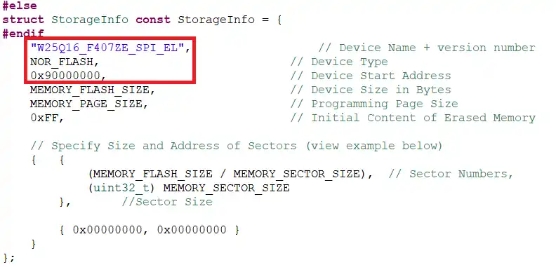
Other details like MEMORY_FLASH_SIZE, PAGE_SIZE, SECTOR_SIZE will be fetched from the W25Qxx.h file.
Now we need to set the linker file for the project.
Go to Project Properties -> C/C++ Build -> Settings -> MCU GCC Linker -> General. Here change the Linker Script to the Linker file we copied.
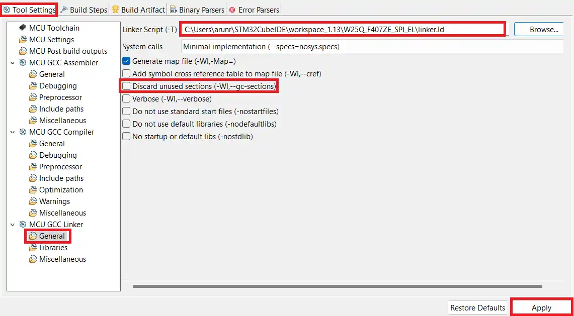
As shown above i have changed the Linker Script to the linker.ld file. Also make sure to uncheck the Discard unused sections. After making the changes, click on Apply.
We also need to copy the post build command to the Build Steps tab as shown below.
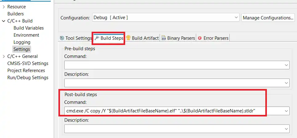
The command is cmd.exe /C copy /Y “${BuildArtifactFileBaseName}.elf” “..\${BuildArtifactFileBaseName}.stldr”. It will copy the stldr file (loader) to the main project folder.
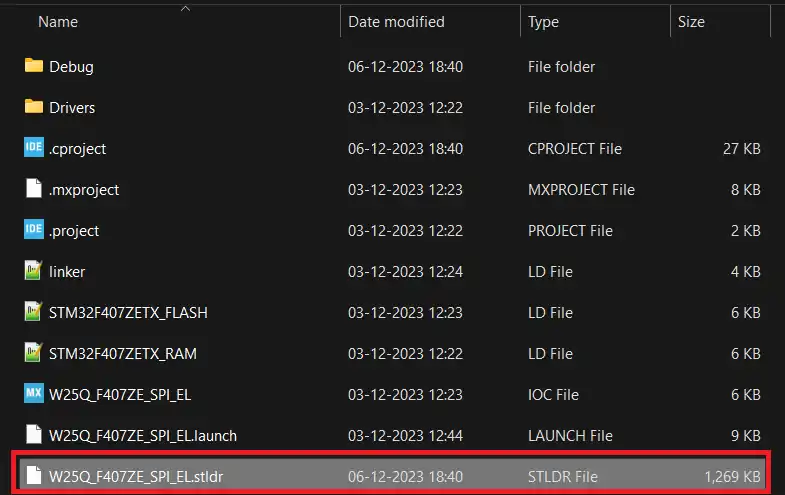
Now build the code, and you should see the Loader file (***.stldr) in the main project folder itself. This is shown below.
The files explained
Changes in W25Qxx
There is no major changes in the W25Qxx library files. I used the same files which we created in the previous tutorials of this series and modified them a little.
I added the memory details in the W25Qxx.h file as shown below.
#define MEMORY_FLASH_SIZE				0x200000 /* 16Mbit =>2Mbyte */
#define MEMORY_BLOCK_SIZE				0x10000   /*  blocks of 64KBytes */
#define MEMORY_SECTOR_SIZE				0x1000    /* 4kBytes */
#define MEMORY_PAGE_SIZE 0x100 /* 256 bytes */Here you only need to change the MEMORY_FLASH_SIZE, if you are using any other chip from winbond. The blocks, sectors and page size remain the same.
i have also added few functions which will be used by the loader source file.
void flash_WriteMemory(uint8_t* buffer, uint32_t address, uint32_t buffer_size);
void flash_ReadMemory (uint32_t Addr, uint32_t Size, uint8_t* buffer);
void flash_SectorErase(uint32_t EraseStartAddress, uint32_t EraseEndAddress);
void flash_ChipErase (void);
void flash_Reset (void);Although we already have the functions to Read, Write, erase, etc, but the loader uses a different set of parameters for them. This is why I have defined new functions for the same. The functions are written in the W25Qxx.c file.
The read function is exactly how we used in the previous tutorials of this series. The loader uses the Address instead of page+offset, so we need to first extract the page and offset from the address and then call our read function.
void flash_ReadMemory (uint32_t Addr, uint32_t Size, uint8_t* buffer)
{
	uint32_t page = Addr/256;  // 1 page occupies 256 bytes
	uint16_t offset = Addr%256;

	W25Q_FastRead(page, offset, Size, buffer);
}Similarly the sector erase function we used takes the sector number as the parameter. On the other hand, the loader uses the start sector and end sector address as the parameters. So we extract the sector numbers from the parameter and then call our function.
void flash_SectorErase(uint32_t EraseStartAddress, uint32_t EraseEndAddress)
{
	uint16_t startSector  = EraseStartAddress/4096;  // 1 sector occupies 4096 bytes
	uint16_t endSector  = EraseEndAddress/4096;
	uint16_t numSectors = endSector-startSector+1;
	for (uint16_t i=0; i<numSectors; i++)
	{
		W25Q_Erase_Sector(startSector++);
	}
}The chip erase and reset functions does not have any parameters, so they are called as it is.
void flash_ChipErase (void)
{
	W25Q_Chip_Erase();
}

void flash_Reset (void)
{
	W25Q_Reset();
}The write function has some changes. The loader itself takes care of when to erase the sector and when to edit the sector, so we don’t need to do it ourselves. We will remove the sector erasing part from our write function and keep the rest of it same. This is shown below.
void flash_WriteMemory(uint8_t* buffer, uint32_t address, uint32_t buffer_size)
{
	uint32_t page = address/256;
	uint16_t offset = address%256;
	uint32_t size = buffer_size;
	uint8_t tData[266];
	uint32_t startPage = page;
	uint32_t endPage  = startPage + ((size+offset-1)/256);
	uint32_t numPages = endPage-startPage+1;

	uint32_t dataPosition = 0;

	// write the data
	for (uint32_t i=0; i<numPages; i++)
	{
		uint32_t memAddr = (startPage*256)+offset;
		uint16_t bytesremaining  = bytestowrite(size, offset);
		uint32_t indx = 0;

		write_enable();

		if (numBLOCK<512)   // Chip Size<256Mb
		{
			tData[0] = W25Q_PAGE_PROGRAM;  // page program
			tData[1] = (memAddr>>16)&0xFF;  // MSB of the memory Address
			tData[2] = (memAddr>>8)&0xFF;
			tData[3] = (memAddr)&0xFF; // LSB of the memory Address

			indx = 4;
		}

		else // we use 32bit memory address for chips >= 256Mb
		{
			tData[0] = W25Q_PAGE_PROGRAM_4B;  // page program with 4-Byte Address
			tData[1] = (memAddr>>24)&0xFF;  // MSB of the memory Address
			tData[2] = (memAddr>>16)&0xFF;
			tData[3] = (memAddr>>8)&0xFF;
			tData[4] = (memAddr)&0xFF; // LSB of the memory Address

			indx = 5;
		}

		uint16_t bytestosend  = bytesremaining + indx;

		for (uint16_t i=0; i<bytesremaining; i++)
		{
			tData[indx++] = buffer[i+dataPosition];
		}

		if (bytestosend > 250)
		{
			csLOW();
			SPI_Write(tData, 100);
			SPI_Write(tData+100, bytestosend-100);
			csHIGH();

		}

		else
		{
			csLOW();
			SPI_Write(tData, bytestosend);
			csHIGH();
		}


		startPage++;
		offset = 0;
		size = size-bytesremaining;
		dataPosition = dataPosition+bytesremaining;

		W25Q_Waitforwrite();
		write_disable();

	}

}Changes in the loader_src file
The original loader files are takes from the ST’s github repo. These files are written for the QSPI peripheral, therefore we need to modify them to be used with the SPI peripheral.
I will compare both the modified code with the original code, so that you understand how it works.
At first we have the loader initialization function.
int Init(void) {

...................

    __HAL_RCC_SPI1_FORCE_RESET();  //completely reset peripheral
    __HAL_RCC_SPI1_RELEASE_RESET();


    MX_SPI1_Init();

    flash_Reset();


    __set_PRIMASK(1); //disable interrupts
    return LOADER_OK;
}
int Init(void) {
...................
__HAL_RCC_QSPI_FORCE_RESET(); //completely reset peripheral
__HAL_RCC_QSPI_RELEASE_RESET();
if (CSP_QUADSPI_Init() != HAL_OK) {
__set_PRIMASK(1); //disable interrupts
return LOADER_FAIL;
}
if (CSP_QSPI_EnableMemoryMappedMode() != HAL_OK) {
__set_PRIMASK(1); //disable interrupts
return LOADER_FAIL;
}
__set_PRIMASK(1); //disable interrupts
return LOADER_OK;
}The default initialization function initializes the QSPI and enables the memory mapped mode. Since we can’t use the memory mapped mode with the SPI peripheral, we will only initialize the SPI here.
Next is the write function.
int Write(uint32_t Address, uint32_t Size, uint8_t* buffer) {

    __set_PRIMASK(0); //enable interrupts

    flash_WriteMemory(buffer, Address, Size);

    __set_PRIMASK(1); //disable interrupts
    return LOADER_OK;
}
int Write(uint32_t Address, uint32_t Size, uint8_t* buffer) {
__set_PRIMASK(0); //enable interrupts
if (HAL_QSPI_Abort(&hqspi) != HAL_OK) {
__set_PRIMASK(1); //disable interrupts
return LOADER_FAIL;
}
if (CSP_QSPI_WriteMemory((uint8_t*) buffer, (Address & (0x0fffffff)), Size) != HAL_OK) {
__set_PRIMASK(1); //disable interrupts
return LOADER_FAIL;
}
__set_PRIMASK(1); //disable interrupts
return LOADER_OK;
}Here the original files calls for the QSPI_WriteMemory function. Instead we will call our flash_WriteMemory function, which uses the SPI peripheral to write the data.
Similar changes are made in the Read, sector erase and chip erase functions. You can download the files and check the code.
There are some major changes in the verify function.
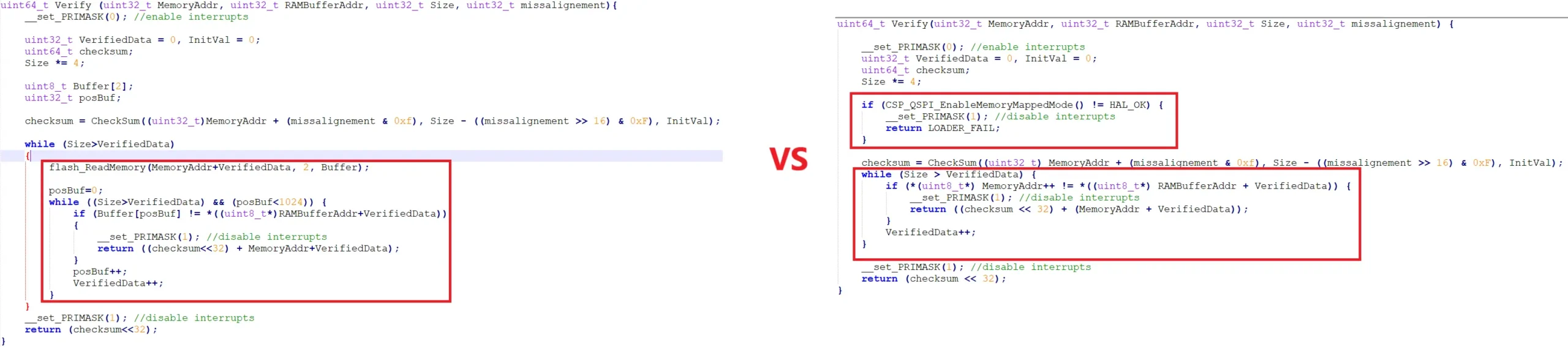
To verify the data, the original code first enables the memory mapped mode and then compares the data at the external memory location. Since we can’t use the memory mapped mode, we will read the data from the external memory and then compare it with our data.
The rest of the operations are same to that of the original file.
How to use the SPI Loader
As I mentioned earlier, we can use the cube programmer to flash the binary file to the external memory and the loader is needed for this operation.
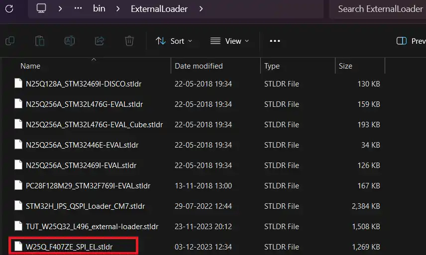
We need to first copy the Loader to the cubeprogrammer directory. Copy the ***.stldr file to the C:\Program Files\STMicroelectronics\STM32Cube\STM32CubeProgrammer\bin\ExternalLoader
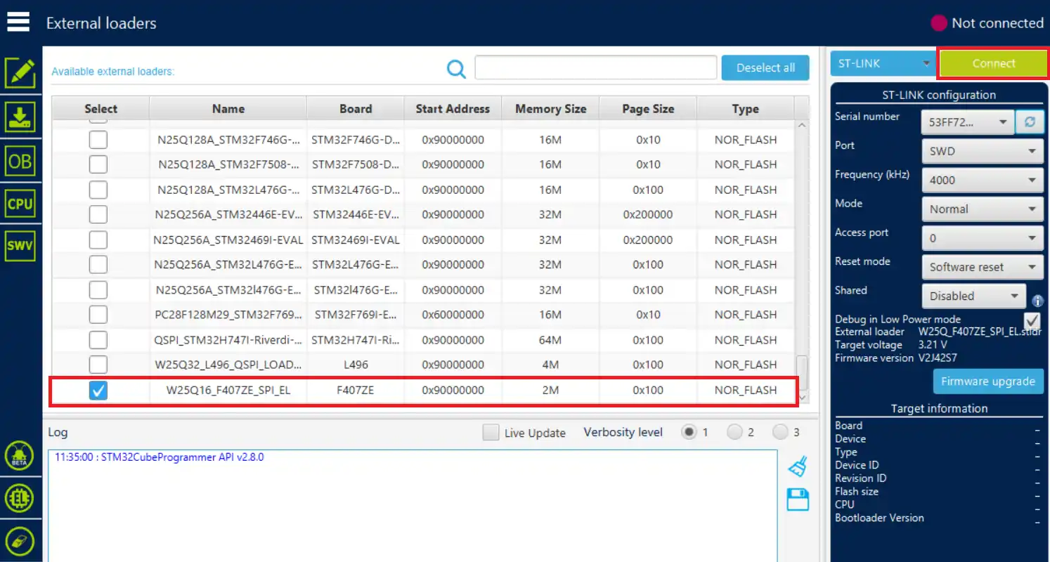
Now open the cube programmer. Go to the EL (External Loader) section and select the loader. Then connect the board to the programmer.
We will program the bin file directly to the flash memory. You can download a test binary file from https://onlinefiletools.com/generate-random-binary-file.
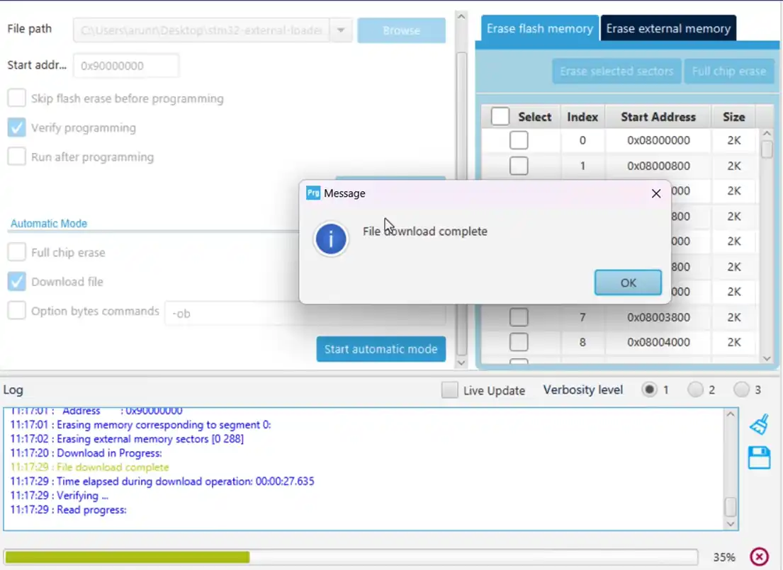
Go to the Download section, Browse the ***.bin, enter the QSPI Start Address, and start programming.
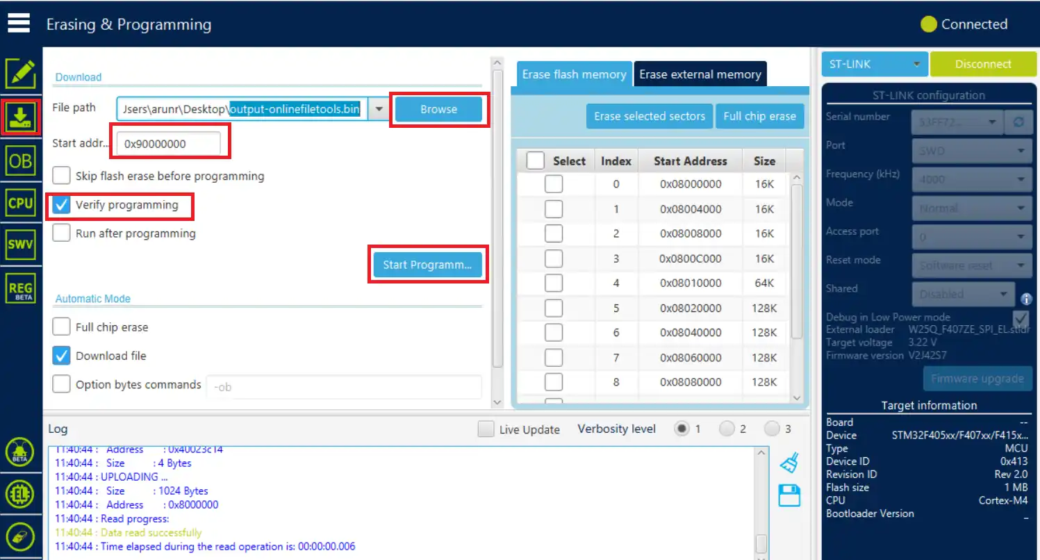
You should see 2 notifications, the first one will pop up once the file has been downloaded to the memory, and another when the downloaded file has been verified.
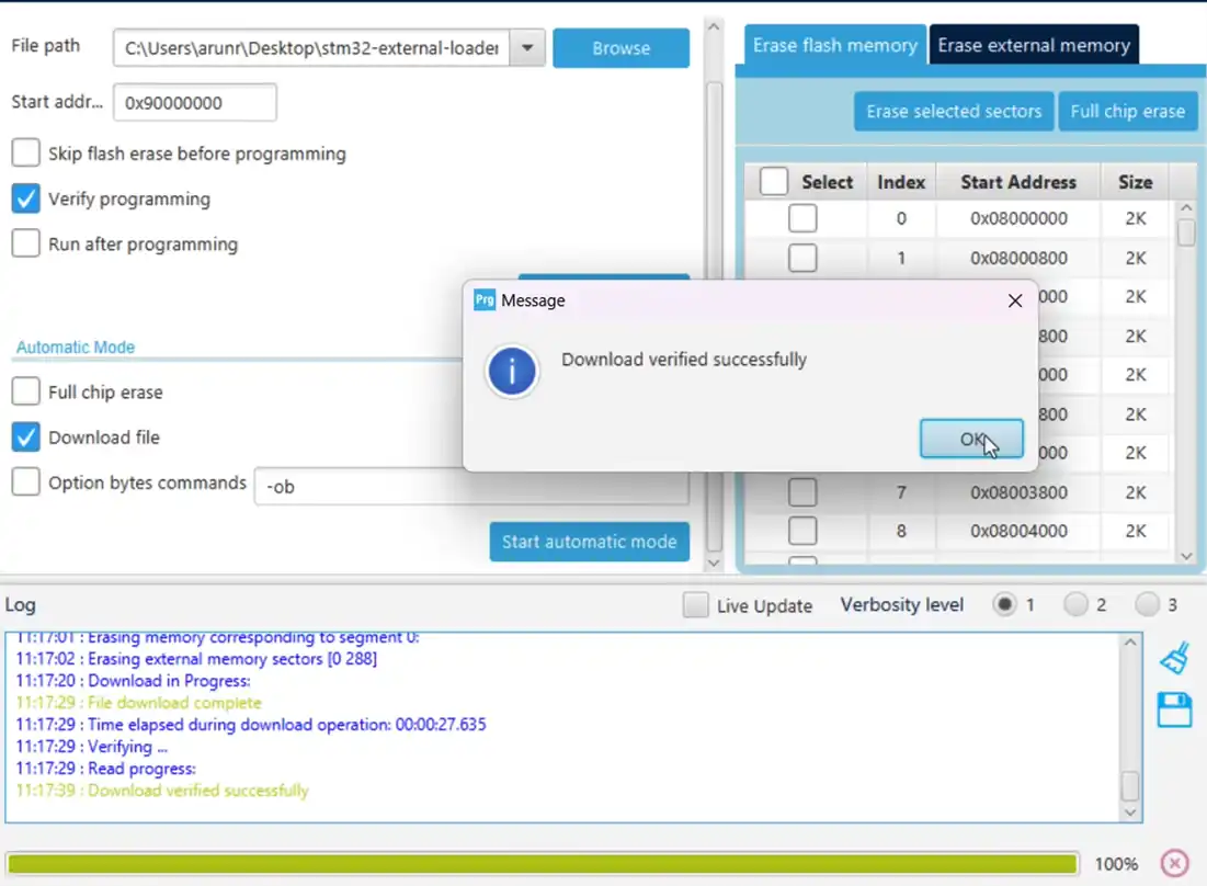
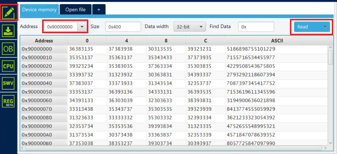
The file has been downloaded and verified means that the external loader is working fine. You can see the content of the external flash in the memory tab.
We can use the cube programmer to flash a binary file to the SPI flash memory. We will use this idea to flash the images, fonts or videos needed for the display, to the external flash, and then read them later in the project.
LVGL have the tools to generate the binary files for the images and fonts. On the other hand, the touchGFX can directly use the SPI flash using the external loader. I will make tutorials on both, the LVGL and the touchGFX, with the SPI flash.
STM32 W25Q Flash Tutorials Series
W25Q Flash Series Part 5 – how to update sectors

W25Q Flash Series Part 6 – Integers floats and 32bit Data
W25Q Flash Series Part 7 – QUADSPI Write, Read, Memory Mapped mode
W25Q Flash Series Part 8 – QUADSPI External Loader
W25Q Flash Series Part 10 – QSPI & Ext Loader in H750
W25Q Flash Series Part 11 – Xecute In Place (XIP)
LVGL on STM32 || PART7 || Load LVGL from Ext Flash


I tried running this project on your configuration, but with no success.
Used the blue-pill with W25Q64. same wiring configuration.