Home ▸ STM32 Tutorials ▸
Updated On: June 20, 2026
LVGL on STM32
In this tutorial series, we will cover how to implement the LVGL on STM32 microcontrollers. This is the first tutorial of the series, which will cover the basic setup and we will get the display to show some output.
I am going to use the 2.8″ TFT ILI9341 SPI display with the STM32L496 nucleo board from ST. The tutorials in this series are going to be more leaned towards the LVGL, so whatever display you are using, you should have the library for it.
The LVGL has a porting guide specific to the STM32 controllers, which can be found Here. We will use this guide to port it to our board.
VIDEO TUTORIAL
You can check the video to see the complete explanation and working of this project.
Step 1 :- Create a new Project
We will first create a new project and setup the SPI. Since we are not implementing the touch in this tutorial, only 1 SPI setup is enough for the display.
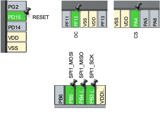
Below is the connection between the LCD and the controller board.

As shown above, other than the SPI pins there are 3 main pins used by the LCD, CS, RESET and DC. These 3 pins must be set as output from the MCU.
The CubeMX setup is shown below.
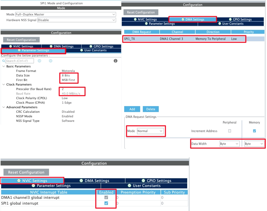
We set up the SPI in 8 bit mode with the baud rate of 40Mbps. The SPI Transmit DMA is enabled in the Normal mode and the data width is set to Byte.
Also make sure to enable the interrupt for the DMA.
Other than the SPI, we have to set 3 more pins as output. They are shown below.
Step 2 :- Add and configure the LVGL directory
We will download the LVGL version 8.3 from their Github. The reason to use the older version is that we are going to use the Squareline Studio for the UI development and it still use the version 8.3 as the newest version.
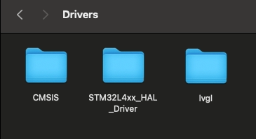
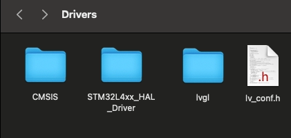
After extracting the folder from the zip, rename it to lvgl and copy in the STM32 Project Folder-> Drivers. This is shown below
Now copy the lv_conf_template.h from inside the lvgl folder, paste it beside the lvgl folder and rename it to lv_conf.h. This is shown in the image below.
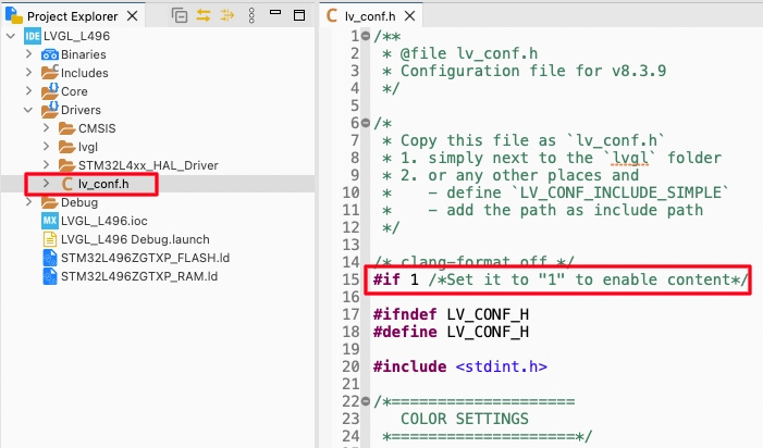
Now refresh the project in cube IDE and you will be able to locate the lv_conf.h in the Drivers directory. Open this file and change the #if 0 to #if 1 so to include the file in the project.
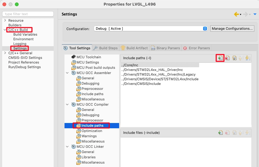
Right click on the project and open Properties.
open the c/c++ Build -> Settings -> MCU GCC Compiler -> Include Paths. Here click the add button to include the lvgl path to the project.
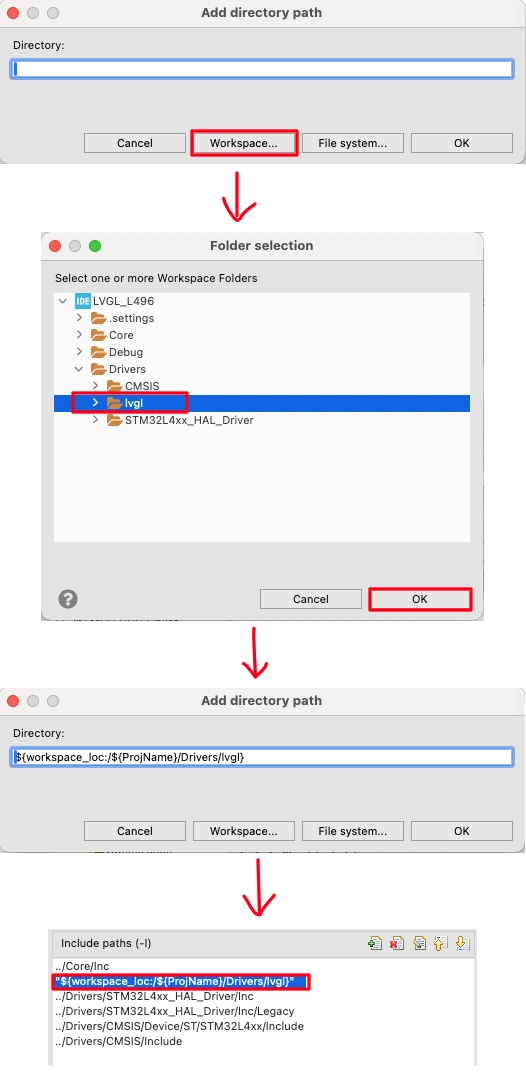
Select the Workspace in the pop up window, locate the lvgl folder we just added and click ok to add the path.
Step 3 :- Connect Display driver to LVGL
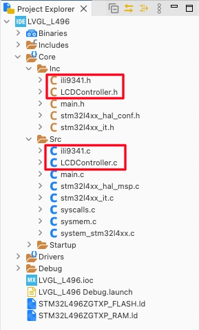
First copy the LCD library files into the project folder and then create new files, LCDController.c and LCDController.h. These are the files where we will connect the LCD library to the LVGL. The project structure with new files is shown below.
The display port template can be found at https://github.com/lvgl/lvgl/blob/release/v8.3/examples/porting/lv_port_disp_template.c. We can simply modify this template as per our need and availability of the MCU and the Display.
The lv_port_disp_init function is used to initialise the display and the display drivers for the LVGL.
void lv_port_disp_init(void)
{
disp_init();The first function inside it is the disp_init(), which is used to initialise the display. Here you need to call the initialisation function for your display.
static void disp_init(void)
{
    ILI9341_Init();
}In the ILI9341 library I am using, the function ILI9341_Init() is used to initialise it. That is why I am calling it inside the disp_init() function.
Next we will define and initialise the draw buffers for the display. You can use a single draw buffer or two draw buffers. Remember that the larger buffer you define, the more memory it is going to occupy. Hence you have to choose wisely between performance vs Space.
One Buffer
If only one buffer is used LVGL draws the content of the screen into that draw buffer and sends it to the display. LVGL then needs to wait until the content of the buffer is sent to the display before drawing something new in it. We can define it as follows:
    static lv_disp_draw_buf_t draw_buf_dsc_1;
    static lv_color_t buf_1[MY_DISP_HOR_RES * 10];                          /*A buffer for 10 rows*/
lv_disp_draw_buf_init(&draw_buf_dsc_1, buf_1, NULL, MY_DISP_HOR_RES * 10); /*Initialize the display buffer*/In the code above, we are defining a single buffer which can hold the data for 10 rows. This means that 10 rows will flush at a time on the display. We can simply send this data to the display by drawing one pixel at a time or by drawing bitmap.
Two Buffers
If two buffers are used LVGL can draw into one buffer while the content of the other buffer is sent to the display in the background. DMA or other hardware should be used to transfer data to the display so the MCU can continue drawing. This way, the rendering and refreshing of the display become parallel operations. We can define 2 buffers as follows:
    static lv_disp_draw_buf_t draw_buf_dsc_2;
    static lv_color_t buf_2_1[MY_DISP_HOR_RES * 10];                        /*A buffer for 10 rows*/
    static lv_color_t buf_2_2[MY_DISP_HOR_RES * 10];                        /*An other buffer for 10 rows*/
lv_disp_draw_buf_init(&draw_buf_dsc_2, buf_2_1, buf_2_2, MY_DISP_HOR_RES * 10); /*Initialize the display buffer*/In the code above, we are defining two buffers that can hold the data for 10 rows each. When one buffer is being flushed to the display using the DMA, the LVGL can update another buffer with new data.
After defining and initialising the buffers, we will setup the rest of the display driver’s parameters.
    lv_disp_drv_init(&disp_drv);                    /*Basic initialization*/

    disp_drv.hor_res = MY_DISP_HOR_RES;
    disp_drv.ver_res = MY_DISP_VER_RES;

    disp_drv.flush_cb = disp_flush;

    disp_drv.draw_buf = &draw_buf_dsc_2;

    lv_disp_drv_register(&disp_drv);
}- Here first of all we will initialise the display driver. Then set the display resolution, which is defined in the beginning of the file.
- The set the flush callback function, which will be called by the LVGL when it is ready to flush the content to the display. We will write this function later.
- Then set the draw buffer which we have defined above (either one buffer or 2 buffers).
- Finally register the display driver.
Now we will write the display flush function. This function is called by the LVGL when it is ready to flush the content to the display. This is the most important function of this file, as it contains the method to send the data to the display.
In this tutorial, we will only cover the simple method of drawing the bitmap and drawing the bitmap using the DMA.
Without DMA
static void disp_flush(lv_disp_drv_t * disp_drv, const lv_area_t * area, lv_color_t * color_p)
{
  ILI9341_SetWindow(area->x1, area->y1, area->x2, area->y2);

  int height = area->y2 - area->y1 + 1;
  int width = area->x2 - area->x1 + 1;

  ILI9341_DrawBitmap(width, height, (uint8_t *)color_p);
  lv_disp_flush_ready(disp_drv);
}- We will first call the function setwindow to set the region which needs to be modified.
- Then calculate the height and width of the area that needs to be modified
- Then the DrawBitmap function will be called to send the data to the area set in the above functions.
- Once the data has been transferred to the display, call the function lv_disp_flush_ready to inform the LVGL that we are ready for ew transfer.
Here the DrawBitmap function sends the data to the display via the SPI in the blocking mode. Below is the implementation of this function in the ILI9341 library.
void ILI9341_DrawBitmap(uint16_t w, uint16_t h, uint8_t *s)
{
	LCD_WR_REG(0x2c);
	DC_H();
	ConvHL(s, (int32_t)w*h*2);
	HAL_SPI_Transmit(&hspi1, (uint8_t*)s, w*h*2, HAL_MAX_DELAY);
}Since the data is being sent in the blocking mode, the function only exits when all the data has been transferred. Therefore calling the function lv_disp_flush_ready immediate after the DrawBitmap function makes sense.
With DMA
If we are using 2 buffers to increase the performance, sending the data using the DMA will help us achieve good performance. Below is the implementation of sending the data using DMA.
static void disp_flush(lv_disp_drv_t * disp_drv, const lv_area_t * area, lv_color_t * color_p)
{
	  ILI9341_SetWindow(area->x1, area->y1, area->x2, area->y2);

	  int height = area->y2 - area->y1 + 1;
	  int width = area->x2 - area->x1 + 1;

	  ILI9341_DrawBitmapDMA(width, height, (uint8_t *)color_p);
}

void HAL_SPI_TxCpltCallback(SPI_HandleTypeDef *hspi)
{
	lv_disp_flush_ready(&disp_drv);

}The initial process of setting window and calculating height and width is same here. The only change is, instead of calling the DrawBitmap, we call the function DrawBitmapDMA. This function uses the DMA to send the data instead of blocking mode SPI transmit.
The DMA sends the data to the SPI in the background without using anu CPU. In the mean time the LVGL will update another buffer with new data. Once the DMA finished the transfer, the interrupt will trigger and the TxCpltCallback will be called.
Inside this callback, we will call the function lv_disp_flush_ready to inform LVGL that we are ready to flush another buffer. This entire system works in a way that the flushing and rendering becomes parallel.
Below is the implementation of the DrawBitmapDMA function in the ILI9341 source file.
void ILI9341_DrawBitmapDMA(uint16_t w, uint16_t h, uint8_t *s)
{
	LCD_WR_REG(0x2c);
	DC_H();
	ConvHL(s, (int32_t)w*h*2);
	HAL_SPI_Transmit_DMA(&hspi1, (uint8_t*)s, w * h *2);
}As you can see the only change is that the data is sent via the SPI DMA instead of sending it using the blocking mode.
We can also use the dedicated GPU (like DMA2D) to send the data to the display. But this only works if you are using display which has the framebuffer in the RAM itself. We will see this in the upcoming tutorials.
Step 4 :- Finish setup and run it
Open the interrupt source file (stm32l4xx_it.c) and add the following in the systick handler.
#include "lvgl.h"  // To be added
.....
void SysTick_Handler(void)
{
  /* USER CODE BEGIN SysTick_IRQn 0 */
	lv_tick_inc(1);  // To be added
  /* USER CODE END SysTick_IRQn 0 */
  HAL_IncTick();
  /* USER CODE BEGIN SysTick_IRQn 1 */

  /* USER CODE END SysTick_IRQn 1 */
}Here we will first include the lvgl.h and then add the lv_tick_inc(1) inside the systick handler.
Next add the LVGL timer handler in the while loop.
  while (1)
  {
    /* USER CODE END WHILE */

    /* USER CODE BEGIN 3 */
	  lv_timer_handler();  // to be added
	  HAL_Delay(5);  // to be added
}This finishes the integration of LVGL with the STM32 controller. Now we will run some test code to see if the display shows some output.
In the main function, initialise the library and the display driver.
lv_init(); //Initialise LVGL UI library
lv_port_disp_init(); // intializse the display driversNow we will add a test code in the main function itself.
// Change the active screen's background color
lv_obj_set_style_bg_color(lv_scr_act(), lv_color_hex(0x003a57), LV_PART_MAIN);


/*Create a spinner*/
lv_obj_t * spinner = lv_spinner_create(lv_scr_act(), 1000, 60);
lv_obj_set_size(spinner, 64, 64);
lv_obj_align(spinner, LV_ALIGN_BOTTOM_MID, 0, 0);The above code sets the background color to Blue. Then it creates a spinner at the bottom of the display.
Result
Below you can see the gif showing the output on the display.

STM32 LVGL Tutorial Series
LVGL on Riverdi STM32-H7 Display
LVGL on STM32 || PART 4
LVGL ON STM32 || PART5
LVGL on STM32 || PART 6
LVGL on STM32 || PART7 || Load LVGL from Ext Flash
STM32 GC9A01 Round Display: SPI & LVGL Integration Guide
STM32 Analog Clock on GC9A01 — LVGL, SquareLine Studio & RTC


Hello, good time, using microstm32g070cbt6, whose flash memory is 128 KB and RAM is 36 KB, using lvgl, I need a w25qxx flash memory to put photos and fonts, for this purpose, how can I use external flash memory for lvgl?
Thank you for your site and good company
Does it support QSPI ?
If yes then https://controllerstech.com/lvgl-on-stm32-part-6/