Home ▸ ESP32 ▸ UART Tutorials ▸
Updated On: May 4, 2026
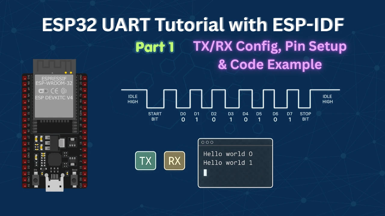
ESP32 UART Tutorial with ESP-IDF: TX/RX Config, Pin Setup & Code Example
UART is the first peripheral to set up when starting any ESP32 project with ESP-IDF. It’s how you print debug output, talk to GPS modules, communicate with other microcontrollers, and relay data to a PC terminal — the same two-wire TX/RX interface you’ll use for nearly everything before wireless comes into play.
In this tutorial you’ll learn how to configure UART2 on the ESP32 using ESP-IDF in blocking mode. We’ll set up the project from the uart_async_rxtxtasks example template, wire the ESP32 to an FT232 USB-to-UART adapter, configure baud rate, data bits, and pin mapping with uart_set_pin(), write a FreeRTOS TX task that transmits a counter string every second, write a FreeRTOS RX task that reads incoming bytes with a timeout, and verify two-way communication in a PC serial terminal. The project files are available to download at the bottom of the page.
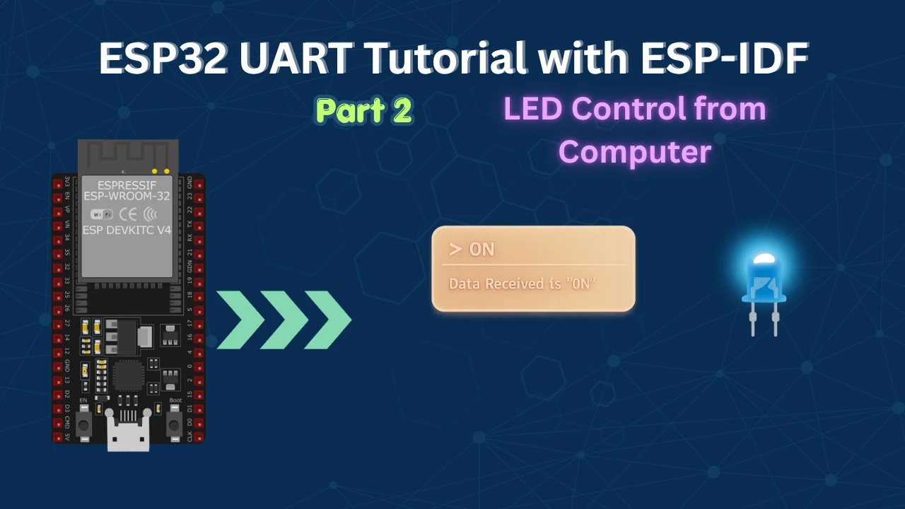
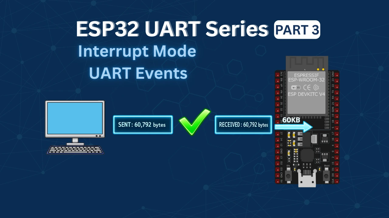
This is Part 1 of the ESP32 UART series. In Part 2 we use the received data to control an LED connected to the ESP32. In Part 3 we cover interrupt-driven reception using UART events — the right approach for any production application. For I2C after this, see LCD1602 via I2C on ESP32 and MPU6050 via I2C on ESP32. For SPI, the three-part series starts at ESP32 SPI Part 1: Configure & Transmit.
ESP32 UART Peripheral: Features & UART Controllers
The ESP32 UART (Universal Asynchronous Receiver/Transmitter) is a hardware communication module that enables serial communication between the ESP32 and other devices. It is widely used for debugging, sensor interfacing, GPS modules, and communication with other microcontrollers. ESP32 supports multiple UART interfaces, each configurable through the ESP-IDF framework.
Key Features of ESP32 UART
- Supports 3 UART controllers (UART0, UART1, UART2)
- Configurable baud rate, stop bits, and parity
- Supports full-duplex communication
- Can operate in interrupt or DMA mode for efficient data handling
ESP32 UART Wiring, Pin Mapping & Project Setup
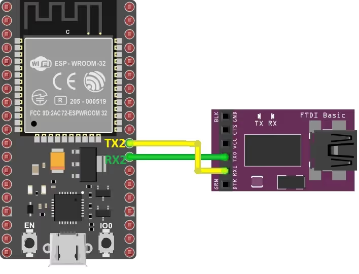
UART2 Wiring: ESP32 to FT232 USB-to-UART Adapter
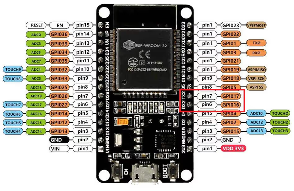
The ESP32 have 3 UARTs, UART0, 1 and 2. I am going to use the UART2 as the pins for UART2 are defined clearly on the board. This is shown in the picture below
As shown in the image above, the RX2 and TX2 pins, GPIO16 and GPIO17 respectively, represents the UART2 pins. The pins must be cross connected, Rx to TX and TX to RX.
| ESP32 Pin | FTDI Connection | Description |
|---|---|---|
| TX2 (GPIO 17) | RX | ESP32 transmits data to FTDI |
| RX2 (GPIO 16) | TX | ESP32 receives data from FTDI |
ESP32 UART Default Pin Mapping by Controller
ESP32 UART interfaces are flexible and allow you to remap TX, RX, RTS, and CTS to almost any GPIO pin. Common pin configurations:
- UART0: TX (GPIO1), RX (GPIO3)
- UART1: TX (GPIO10), RX (GPIO9)
- UART2: TX (GPIO17), RX (GPIO16)
You can override default pins using uart_set_pin(). This is particularly useful if your board uses certain pins for other purposes.
Creating a New ESP-IDF Project from the uart_async_rxtxtasks Template
Follow these steps to create a new ESP-IDF project and configure the environment to program the ESP32 UART interface.
We will first create a project using the examples provided in the IDE by default. Later we will modify it according to our need.
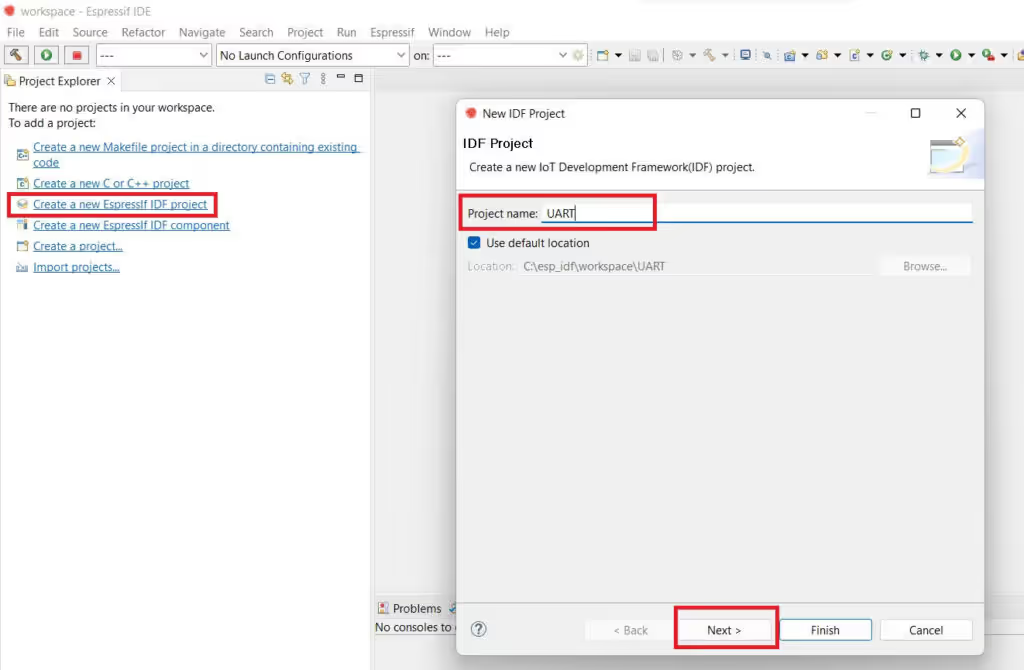
- Fist we will create a new Espressif IDF project
- Then give some name to this project and click next
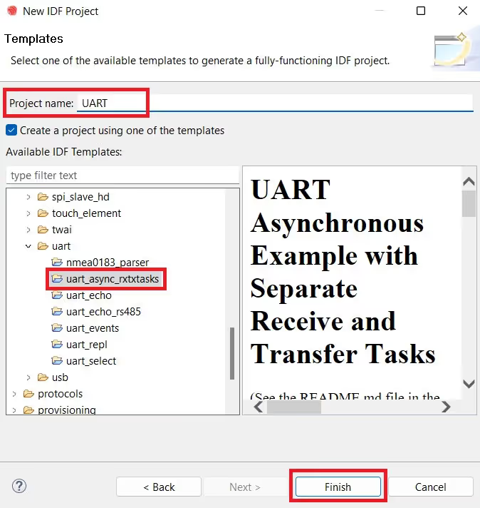
- Check “Create project using one of the templates”
- Goto Peripherals -> uart and select the “uart_async_rxtxtasks”
- The name of the project will be modified after this, so make sure you change it back
- Click finish to generate the project
The example we chose above is simplest example to start with uart. The ESP32 also supports interrupt and DMA for uart, but in this tutorial we will do the simplest method of sending and receiving data, i.e using the blocking mode.
The code will generate and you can find the main.c file in the main folder. The pre-generated code will also work pretty well, but here I will modify it a little and explain you the entire code.
ESP32 UART Code Example: Driver Init, TX Task & RX Task
Use this practical C code example to send and receive data over UART on ESP32 using the ESP-IDF framework.
Definitions: Buffer Size, Pins and UART Number
static const int RX_BUF_SIZE = 128;

#define TXD_PIN (GPIO_NUM_17)
#define RXD_PIN (GPIO_NUM_16)

#define UART_NUM UART_NUM_2- First the Rx buffer size is defined as 128 Bytes
- I have modified the Tx and Rx Pins as per my setup
- As I mentioned before, I am going to use the UART2 in this tutorial, so I have defined the UART_NUM as UART_NUM_2
- Now we can just simply use the UART_NUM wherever the uart number is needed to be provided.
Initializing the UART Driver with uart_driver_install()
void init(void)
{
    const uart_config_t uart_config = {
        .baud_rate = 115200,
        .data_bits = UART_DATA_8_BITS,
        .parity = UART_PARITY_DISABLE,
        .stop_bits = UART_STOP_BITS_1,
        .flow_ctrl = UART_HW_FLOWCTRL_DISABLE,
        .source_clk = UART_SCLK_DEFAULT,
    };

    // We won't use a buffer for sending data.
    uart_driver_install(UART_NUM, RX_BUF_SIZE * 2, 0, 0, NULL, 0);
    uart_param_config(UART_NUM, &uart_config);
    uart_set_pin(UART_NUM, TXD_PIN, RXD_PIN, UART_PIN_NO_CHANGE, UART_PIN_NO_CHANGE);
}uart_driver_install(UART_NUM, RX_BUF_SIZE * 2, 0, 0, NULL, 0);- First of all we will install the UART Driver. The
uart_driver_installfunction takes the following argument- @
uart_port_t, The UART Instance you are using, UART2 in this example - @
int rx_buffer_size, The size of the RX Ring Buffer. It should be greater than minimum length, which is defined in the soc_caps.h file#define SOC_UART_FIFO_LEN (128). Here the RX_BUF_SIZE is multiplied by 2, so the Ring Buffer Size will be 256 Bytes. - @
int tx_buffer_size, The size of the TX Ring Buffer. We are not using the TX FIFO, so the size is set to 0 in this example. - @
int queue_size, The UART Queue size, 0 in this case since we are not using any queue in this tutorial - @
QueueHandle_t *uart_queue, The UART queue, NULL in this example since we are not using the queue - @
int intr_alloc_flags, The interrupt FLAG, 0 in this example since we are not using interrupt
- @
Configuring UART Parameters with uart_param_config()
Next, we will configure the UART parameters.
uart_param_config(UART_NUM, &uart_config);The configuration used is 8-N-1 with the baud rate of 115200. Hardware flow control is disabled and the UART source clock is set to DEFAULT, which is actually the APB clock.
uart_set_pin(UART_NUM, TXD_PIN, RXD_PIN, UART_PIN_NO_CHANGE, UART_PIN_NO_CHANGE);- Finally we will set the pins for the UART. The
uart_set_pinfunction takes the following parameters- @
uart_port_t, The UART_NUM you are using, UART2 in this example - @
int tx_io_num, The TX Pin number, GPIO_NUM_17 in this example - @
int rx_io_num, The RX Pin number, GPIO_NUM_16 in this example - @
int rts_io_numand @int cts_io_num, The RTS and CTS Pin numbers. We are not using hardware flow control so these parameters are set toUART_PIN_NO_CHANGE(-1).
- @
UART Transmit Task: Sending Data Every 1 Second
static void tx_task(void *arg)
{
    int num = 0;
    uint8_t* data = (uint8_t*) malloc(30);
    while (1) {
    	int len = sprintf ((char*)data, "Hello world %d\n", num++);
        uart_write_bytes(UART_NUM, data, len);
        vTaskDelay(1000 / portTICK_PERIOD_MS);
    }
    free (data);
}The TX task will send the data via the UART every 1 second.
- First we will allocate the 30 bytes to the data buffer, where we will store the data to be transmitted.
- The num variable will be updated every time the data is transmitted, so that we have a new data each time.
- Next we will store the data into the data buffer. Here we will increment the value of the num variable so that the data will be different each time.
uart_write_byteswill be used to write the data. The function takes the following parameters- @
uart_port_t, The UART Instance you are using, UART2 in this example. - @
const void* src,The pointer to the source address, data in this example. - @
size_t size, The length of the data to be transmitted, len in this example.
- @
- At last we will free the allocated memory to the data buffer.
UART Receive Task: Reading Bytes with Timeout
static void rx_task(void *arg)
{
    static const char *RX_TASK_TAG = "RX_TASK";
    esp_log_level_set(RX_TASK_TAG, ESP_LOG_INFO);
    uint8_t* data = (uint8_t*) malloc(RX_BUF_SIZE+1);
    while (1) {
        const int rxBytes = uart_read_bytes(UART_NUM, data, RX_BUF_SIZE, 200 / portTICK_RATE_MS);
        if (rxBytes > 0) {
            data[rxBytes] = 0;
            ESP_LOGI(RX_TASK_TAG, "Read %d bytes: '%s'", rxBytes, data);
        }
    }
    free(data);
}- RX Task will be used to receive the data from the UART and then log the received data to the terminal.
- Here we will first create the RX_TASK_TAG, which will be used to log the information data to the terminal.
- Then allocate the memory to the data buffer, where the received data will be stored. The allocated memory is 1 byte higher than the RX_BUF_SIZE as we will add a ‘0’ at the end of this buffer, so to mark the termination of the received data.
- Receive the data using the function
uart_read_bytes. It takes the following parameters.- @
uart_port_t, The UART Instance you are using, UART2 in this example. - @
void* buf, The pointer to the buffer where the data will be saved, data in this example. - @
uint32_t length, The length of the buffer, 128 bytes in this example. - @
TickType_t ticks_to_wait, The time to wait for the data to arrive, 200 ms in this example. - @
ESP_LOGI, is used to log the received data to the terminal.
- @
If the required amount of data (RX_BUF_SIZE) does not arrive in 200ms, the timeout will occur. Whatever data was received in this 200ms will be stored in the data buffer. This data is then logged to the terminal.
At the end, we free the memory allocated to the data buffer.
app_main(): Creating TX and RX FreeRTOS Tasks
void app_main(void)
{
    init();
    xTaskCreate(rx_task, "uart_rx_task", 1024*2, NULL, configMAX_PRIORITIES-1, NULL);
    xTaskCreate(tx_task, "uart_tx_task", 1024*2, NULL, configMAX_PRIORITIES-2, NULL);
}- In the main function, we will first initialize the UART
- Then we are creating 2 tasks, rx_task and tx_task
- The stack size for both the tasks is set to 2 Kilobytes
- The priority of the receiver task is highest, and that of the transmitter task is 1 below the receiver task
- After the Tasks has been created, the transmitter task will start sending the data to the UART and Receiver task will wait for the data to be received.
ESP32 UART Result: Serial Terminal Output
Below is the output of the serial terminal and the ESP32 Terminal.
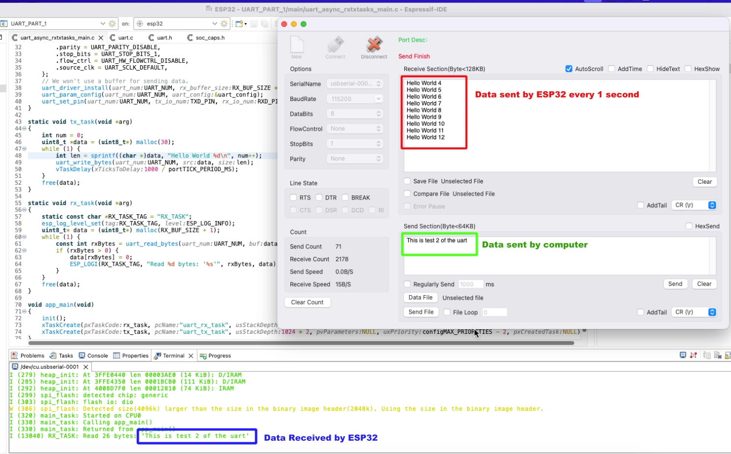
As you can see the Serial terminal is receiving the data sent by the ESP32 every 1 seconds. The data is updated with the new number each time it is sent.
When we send some data from the terminal to the ESP, it gets logged into the ESP terminal.
ESP32 UART with ESP-IDF — Video Tutorial
Watch the complete walkthrough of this tutorial — creating a new ESP-IDF project from the uart_async_rxtxtasks template, wiring the ESP32 to an FT232 USB-to-UART adapter, configuring UART2 at 115200 baud with uart_param_config(), remapping TX/RX pins with uart_set_pin(), writing the FreeRTOS TX task to transmit a counter string every second, writing the RX task to receive data with a 200ms timeout, and verifying two-way communication in a PC serial terminal.
ESP32 UART with ESP-IDF: Frequently Asked Questions
Conclusion
At this point you have a fully working UART setup on the ESP32: the driver is installed, TX and RX are running as separate FreeRTOS tasks with independent priorities, and you've verified two-way communication through a PC serial terminal. The blocking uart_read_bytes() approach used here is simple and reliable for low-throughput applications where a fixed 200ms read timeout is acceptable.
The important limitation to understand: blocking mode ties the RX task to a fixed polling interval. If incoming bytes arrive faster than your timeout window, or if you need to react to a specific delimiter or packet boundary, blocking mode will miss data or force unnecessary delays. That's exactly what Part 3 fixes — ESP32 UART with UART Events replaces the blocking uart_read_bytes() loop with an event-driven approach where the ESP32 notifies your task the moment data arrives, a timeout occurs, or the FIFO fills up. For any production firmware, that's the version to use.
From here the natural path is: Part 2 to see how the received string is parsed to control hardware (an LED in that case), then Part 3 for interrupt-driven UART events. After UART, the ESP32 I2C series and ESP32 SPI series follow the same ESP-IDF driver-install pattern — the concepts carry over directly.
Download ESP32 UART ESP-IDF Project Files
Complete ESP-IDF project with UART2 driver initialization, FreeRTOS TX and RX tasks, pin configuration for FT232 wiring — tested on ESP32 DevKit. Free to download — support the work if it helped you.
Browse More ESP32 UART Tutorials


Can UART be implement using intrupt method like other microcontrollers? If yes can you guide me please?
i am trying to communicate with ec200 ucn gsm module, and sending AT commands via esp32 uart 0, getting response back but , not able to read proper reading of gsm module response because it takes time to respond back, so i am not able to when to send next at command , I simply wanted to send data to server via gsm moudle
if you can manage socket command library(AT commands), I think you can use esp_modem. There is a few example like modem tcp client, simple cmux client etc. I have tested the mqtt connection over tcp/ip protocol it works!
where is the free of Txdata ?
Hi, Thanks for this. There is an interesting observation which I like to share:
My application had only 10bytes of rx data so I redefined RX_BUF_SIZE to 10. Apparently ESP32 driver install API doesnot like this. RX_BUF_SIZE must be always >128 bytes else it throws error.
This might help someone!