Home ▸ STM32 Tutorials ▸
Updated On: May 22, 2026
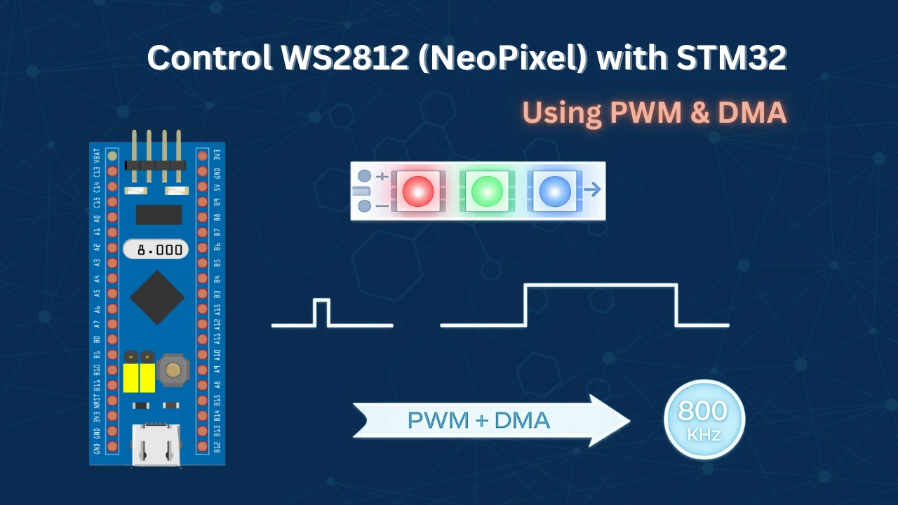
STM32 WS2812 (NeoPixel) Control Using PWM + DMA
WS2812 addressable RGB LEDs (also known as NeoPixels) have become incredibly popular for lighting projects due to their chainable design and vibrant color control.
In this tutorial, I’ll show you how to control WS2812 and WS2812B LEDs using an STM32 microcontroller with a hardware-based approach: PWM combined with DMA (Direct Memory Access). This method generates the precise timing signals required by the LEDs while leaving your CPU free to handle other tasks.
We’ll walk through the complete implementation step-by-step, including:
- Configuring the timer and DMA in STM32CubeMX
- Understanding the WS2812 timing protocol from the datasheet
- Writing efficient code to convert RGB values into PWM signals
- Adding brightness control with smooth fading effects
Prerequisites
Before diving into this tutorial, you should have a basic understanding of PWM (Pulse Width Modulation) on STM32. If you’re new to PWM or need a refresher, I recommend checking out my PWM in STM32 tutorial first, as it covers the fundamentals we’ll be building upon here.
Understanding the WS2812 Protocol
The WS2812 uses a single-wire communication protocol with precise timing requirements. Understanding how data is encoded and transmitted is essential before we dive into the implementation. Let’s break down the key concepts from the datasheet.
Encoding Data: Logic 0 and Logic 1
Below is the picture from the datasheet, explaining how to send a 0 and a 1 to the device:
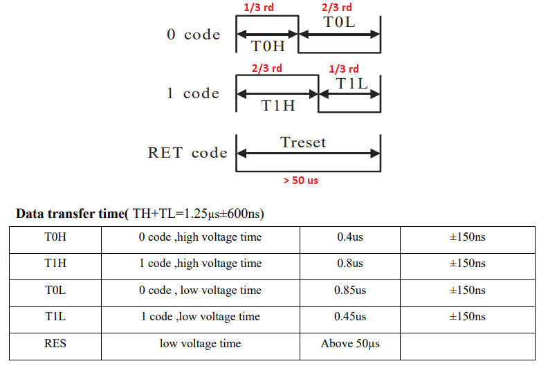
The WS2812 distinguishes between binary 0 and 1 based on the duty cycle of the signal:
- To send a Logic 0: The pulse should be HIGH for 0.4 µs, then LOW for 0.85 µs. This works out to approximately 1/3 of the total pulse width being HIGH.
- To send a Logic 1: The pulse should be HIGH for 0.8 µs, then LOW for 0.45 µs. This creates a duty cycle where approximately 2/3 of the pulse is HIGH.
- Reset Code: A LOW pulse lasting more than 50 µs signals the end of data transmission and latches the color values to the LEDs.
Data Structure and Bit Order
Next, we have the bit arrangement:
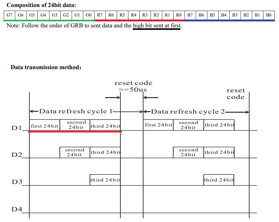
Each WS2812 LED requires 24 bits of color data, organized in a specific format:
- 24-bit Color Format: Green (8 bits) + Red (8 bits) + Blue (8 bits) – in that exact order (GRB, not RGB!)
- Transmission Order: The most significant bit (MSB) of Green is sent first, followed by the remaining bits in descending order.
- Cascading Multiple LEDs: When controlling multiple LEDs, all data must be sent consecutively. For example, 12 LEDs require 12 × 24 = 288 bits transmitted one after another without interruption.
- LED Addressing: The WS2812 driver automatically routes data – the first 24 bits go to the first LED, the next 24 bits to the second LED, and so on down the chain.
- Critical Timing: After sending data for all LEDs, you must maintain a LOW signal for more than 50 µs. If this reset period is too short, the driver interprets incoming data as belonging to additional LEDs in the chain.
With this understanding of the WS2812 protocol, we’re now ready to implement the code that generates these precise timing signals using STM32’s PWM and DMA capabilities.
STM32CubeMX Configuration
We’ll use STM32CubeMX to set up the timer for PWM generation and configure DMA to handle data transfer automatically.
The key to this implementation is matching our timer frequency to the WS2812’s timing requirements. Since each bit needs to be transmitted at 800 kHz (1.25 µs period), we’ll configure our timer to operate at this exact frequency. Then, by varying the PWM duty cycle, we can create the different pulse widths needed for logic 0 (33% duty) and logic 1 (67% duty).
Clock Configuration
We will start with the clock configuration first. I am using external crystal to provide the clock and using PLL, the system is running t 72MHz.
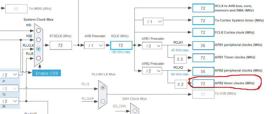
Also note that the APB2 Timer Clock is running at 72 MHz. I am going to use TIM1 and it is connected to APB2 bus.
Timer Configuration
Now we will enable the Timer 1 in the PWM output mode. The image below shows the timer configuration.
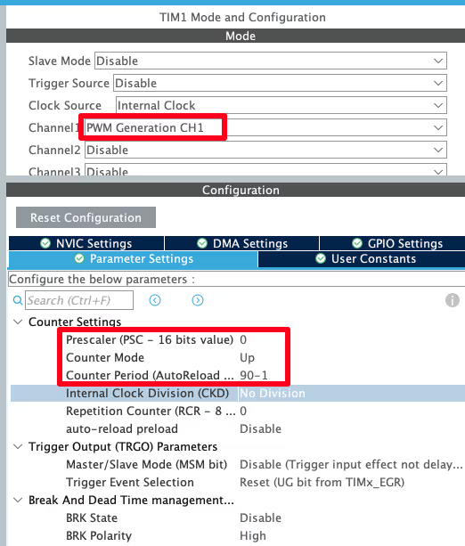
- Since the Timer 1 is connected to the APB2 clock, it was initially running at 72 MHz
- Now we use prescalar of 0, that means we are diving this Frequency by 1, So the timer is still running at same 72 MHz frequency
- The ARR of 90 will bring down this timer frequency to 72 MHz/90 = 800 KHz
- Also this 90 in the ARR is the maximum duty cycle i.e 100% Duty = 90 (in the CCR)
- Now if we want to change the duty cycle, we have to calculate the percentage from 90
- For example, if we want the duty cycle of 30%, we will use the value 27, and for 70% Duty, the value will be 63
Note:
Calculate the ARR and CCR values for the STM32F4 Timers using the STM32F4 PWM Tool:
https://controllerstech.com/tools/stm32f4-pwm-calculator/
We also need to configure the Timer DMA. The image below shows the DMA configuration.
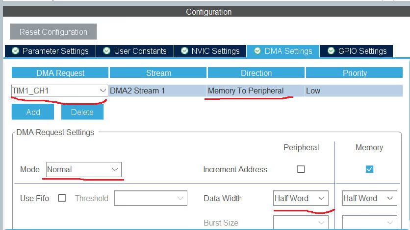
- DMA is set for TIM1 channel 1
- Memory to peripheral direction is needed, since we are sending the data to the peripheral
- Use the normal mode, since we only want the DMA to transfer the data, when we command it to do so
- I am using the data width of half word here, for no particular reason
That is all we need to configure in the CubeMX.
Verifying PWM and DMA Operation
Before implementing the complete WS2812 driver, it’s crucial to verify that our PWM and DMA configuration is working correctly. This test will confirm that our timer generates the correct frequencies and duty cycles, and that DMA successfully transfers our bit patterns to the PWM peripheral.
Test Code Implementation
The following code demonstrates a minimal PWM-DMA implementation that sends a single 24-bit color value:
int datasentflag=0;

void HAL_TIM_PWM_PulseFinishedCallback(TIM_HandleTypeDef *htim)
{
	HAL_TIM_PWM_Stop_DMA(htim, TIM_CHANNEL_1);
	datasentflag = 1;
}

uint16_t pwmData[24];

void WS2812_Send (uint32_t color)
{
	for (int i=23; i>=0; i--)
	{
		if (color&(1<<i))
		{
			pwmData[i] = 66;
		}
		else pwmData[i] = 33;
	}

	HAL_TIM_PWM_Start_DMA(&htim1, TIM_CHANNEL_1, (uint32_t *)pwmData, 24);
	while (!datasentflag){};
	datasentflag = 0;
}

int main(void)
{
  HAL_Init();

  SystemClock_Config();

  MX_GPIO_Init();
  MX_DMA_Init();
  MX_TIM1_Init();

  uint32_t colour = 0x347235;  // RGB color code to test
  WS2812_Send(colour);

  while (1)
  {

  }
}How the Test Code Works
Let’s break down what’s happening in this verification code:
Data Encoding:
- The
colorvariable is a 32-bit container holding our 24-bit RGB color code (in this example,0x347235) - We iterate through each bit of the color value from MSB to LSB (bits 23 down to 0)
- For each bit that equals 1, we store the value 66 in the
pwmDatabuffer (representing ~66% duty cycle for logic 1) - For each bit that equals 0, we store the value 33 (representing ~33% duty cycle for logic 0)
- The MSB-first order matches the WS2812’s requirement to receive the most significant bits first
DMA Transfer:
- Once the buffer is populated,
HAL_TIM_PWM_Start_DMA()initiates the transfer of all 24 values to the timer’s capture/compare register - The
datasentflagensures the function waits until transmission completes before returning - When DMA finishes,
HAL_TIM_PWM_PulseFinishedCallback()stops the DMA channel and sets the flag, preventing automatic retransmission
Oscilloscope Results
I have connected an oscilloscope to PWM output pin to verify the signal. The image below shows bit timing measured on the scope.
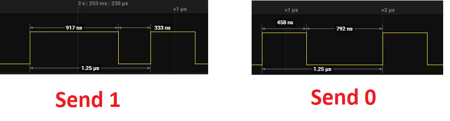
- The period measures 1.25 µs, which matches our target 800 kHz frequency perfectly
- Logic ‘1’ maintains HIGH for ~917 ns and LOW for ~333 ns, creating approximately 73% duty cycle (target: 67%)
- Logic ‘0’ maintains HIGH for ~458 ns and LOW for ~792 ns, creating approximately 36% duty cycle (target: 33%)
Why the slight deviation? The measured duty cycles (73% and 36%) are close to our targets (67% and 33%). This small variance is within the WS2812’s tolerance range and occurs due to integer rounding when calculating CCR values from the ARR period.
The image below shows the complete 24 bit data sent by the STM32.
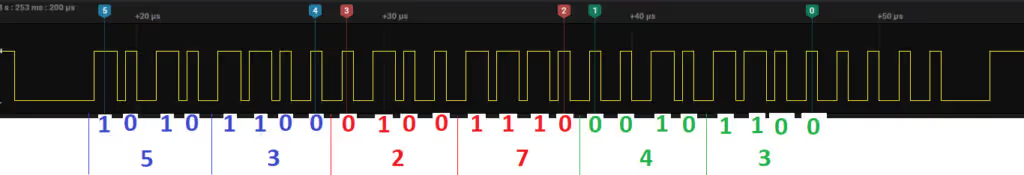
- The green channel bits (MSB) are transmitted first, as required by the WS2812 protocol
- Reading the signal from right to left, you can decode the binary pattern back to
0x347235, confirming correct bit transmission
With PWM and DMA now verified and working correctly, we’re ready to build the complete WS2812 driver that handles multiple LEDs, color management, and brightness control.
STM32 HAL Code to interface WS2812
With our PWM and DMA configuration verified and working correctly, we’re now ready to build the complete WS2812 driver.
Some Definitions
#define MAX_LED 8
#define USE_BRIGHTNESS 1

uint8_t LED_Data[MAX_LED][4];
uint8_t LED_Mod[MAX_LED][4]; // for brightness- Define the Maximum LEDs Connected in cascade
- USE_BRIGHTNESS can be set to 1, if you want to use the brightness control. Or set it to 0
- LED_Data and LED_Mode are the matrices to store the LED related data.
Storing the LED data
void Set_LED (int LEDnum, int Red, int Green, int Blue)
{
	LED_Data[LEDnum][0] = LEDnum;
	LED_Data[LEDnum][1] = Green;
	LED_Data[LEDnum][2] = Red;
	LED_Data[LEDnum][3] = Blue;
}

#define PI 3.14159265

void Set_Brightness (int brightness)  // 0-45
{
#if USE_BRIGHTNESS

	if (brightness > 45) brightness = 45;
	for (int i=0; i<MAX_LED; i++)
	{
		LED_Mod[i][0] = LED_Data[i][0];
		for (int j=1; j<4; j++)
		{
			float angle = 90-brightness;  // in degrees
			angle = angle*PI / 180;  // in rad
			LED_Mod[i][j] = (LED_Data[i][j])/(tan(angle));
		}
	}

#endif

}LED_Datais used to store the color data for individual LED. Here First Column Represents the LED number, 2nd column for Green, then Red and Last column for blue colorLED_Modis also used to store LED related data, but the scaled values, as per the brightness settings- Controlling the Brightness is fairly simple. All we need to so is divide the actual value by some number. For eg- Red 255 will be brightest, 127 will be 50% bright and 63 will be 25% bright
- I am using the Tangent function to bring some linearity in the scaling.
- The brightness values can vary from 0 to 45
Convert and send the data to DMA
uint16_t pwmData[(24*MAX_LED)+50];

void WS2812_Send (void)
{
	uint32_t indx=0;
	uint32_t color;


	for (int i= 0; i<MAX_LED; i++)
	{
#if USE_BRIGHTNESS
		color = ((LED_Mod[i][1]<<16) | (LED_Mod[i][2]<<8) | (LED_Mod[i][3]));
#else
		color = ((LED_Data[i][1]<<16) | (LED_Data[i][2]<<8) | (LED_Data[i][3]));
#endif

		for (int i=23; i>=0; i--)
		{
			if (color&(1<<i))
			{
				pwmData[indx] = 60;  // 2/3 of 90
			}

			else pwmData[indx] = 30;  // 1/3 of 90

			indx++;
		}

	}

	for (int i=0; i<50; i++)
	{
		pwmData[indx] = 0;
		indx++;
	}

	HAL_TIM_PWM_Start_DMA(&htim1, TIM_CHANNEL_1, (uint32_t *)pwmData, indx);
	while (!datasentflag){};
	datasentflag = 0;
}Converting Color Data to PWM Values
The WS2812_Send() function performs the critical task of converting RGB color data into the precise PWM duty cycle values that the LEDs understand. Let’s walk through this conversion process step by step.
Building the 24-bit Color Word: First, we combine the individual Green, Red, and Blue bytes into a single 24-bit value. This consolidation makes it easier to process each bit sequentially:
color = ((LED_Mod[i][1]<<16) | (LED_Mod[i][2]<<8) | (LED_Mod[i][3]));The Green byte is shifted to the most significant position (bits 23-16), Red occupies the middle (bits 15-8), and Blue takes the least significant position (bits 7-0), creating the GRB format the WS2812 requires.
Bit-by-Bit Encoding: Next, we examine each of the 24 bits and convert them to PWM duty cycle values:
for (int i=23; i>=0; i--)
{
    if (color&(1<<i))
    {
        pwmData[indx] = 60;  // 2/3 of 90
    }
    else
    {
        pwmData[indx] = 30;  // 1/3 of 90
    }
    indx++;
}- For a logic 1: We store 60 in the buffer, which represents 60/90 = 67% duty cycle (approximately 2/3)
- For a logic 0: We store 30, which represents 30/90 = 33% duty cycle (approximately 1/3)
These values directly correspond to the timing requirements from the WS2812 datasheet. Since our ARR is set to 90 (representing 100% duty cycle), these CCR values create the correct pulse widths.
MSB-First Transmission: Notice that we iterate from bit 23 down to bit 0 (i=23; i>=0; i--). This ensures the most significant bit is placed first in the buffer, matching the WS2812’s requirement to receive the Green MSB before all other bits.
Adding the Reset Signal: After encoding all LED data, we must append a reset period to latch the colors:
for (int i=0; i<50; i++)
{
    pwmData[indx] = 0;
    indx++;
}By adding 50 consecutive zeros (0% duty cycle = continuous LOW), we create a LOW pulse lasting 50 × 1.25 µs = 62.5 µs. This exceeds the WS2812’s 50 µs minimum reset requirement, ensuring the LED controller recognizes the end of the data stream and updates all LEDs with their new colors.
Initiating the DMA Transfer: Finally, we trigger the DMA to send our complete PWM buffer:
HAL_TIM_PWM_Start_DMA(&htim1, TIM_CHANNEL_1, (uint32_t *)pwmData, indx);The DMA now handles the entire transmission automatically, freeing the CPU to perform other tasks while the LED colors update.
Managing DMA Completion
After the DMA controller finishes transferring all PWM values to the timer peripheral, we need to cleanly stop the operation and signal that the LED update is complete. This prevents unwanted retransmission and allows our main code to know when it’s safe to prepare the next update.
The Pulse Finished Callback
The HAL library provides a dedicated callback function that executes automatically when DMA completes its transfer:
void HAL_TIM_PWM_PulseFinishedCallback(TIM_HandleTypeDef *htim)
{
HAL_TIM_PWM_Stop_DMA(&htim1, TIM_CHANNEL_1);
datasentflag = 1;
}What happens in this callback:
- Stop the DMA channel:
HAL_TIM_PWM_Stop_DMA()immediately halts the DMA transfer and disables the timer’s DMA request. This is crucial because without explicitly stopping it, the DMA could automatically restart or interfere with the next transmission. - Set the completion flag: The
datasentflagis set to 1, signaling to ourWS2812_Send()function that the transmission has finished successfully. This flag allows the main code to proceed safely without risking data corruption from overlapping transfers.
The main Function
Inside the main function, we will set different LEDs. The code below demonstrates this.
int main(void)
{
HAL_Init();
SystemClock_Config();
MX_GPIO_Init();
MX_DMA_Init();
MX_TIM1_Init();
Set_LED(0, 255, 0, 0);
Set_LED(1, 0, 255, 0);
Set_LED(2, 0, 0, 255);
Set_LED(3, 46, 89, 128);
Set_LED(4, 156, 233, 100);
Set_LED(5, 102, 0, 235);
Set_LED(6, 47, 38, 77);
Set_LED(7, 255, 200, 0);
while (1)
{
for (int i=0; i<46; i++)
{
Set_Brightness(i);
WS2812_Send();
HAL_Delay (50);
}
for (int i=45; i>=0; i--)
{
Set_Brightness(i);
WS2812_Send();
HAL_Delay (50);
}
}
}- Here first of all I am setting the different colors to the LEDs
- Inside the while loop, I am increasing the brightness every 50 ms
- and then decreasing the brightness. You can see the Result below
- Note that after setting the LED, you must call
WS2812_Sendfunction, to send the data to the LED - I am calling that function inside the while loop
Output of WS2812 LEDs
The gif below shows the WS2812 LEDs, connected to STM32, glowing in a pattern.
You can check out the detailed working and more patterns in the video below.
Video Tutorial
STM32 WS2812 (NeoPixel) Interface – Video Tutorial
This tutorial shows how to interface WS2812 (NeoPixel) LEDs with STM32 using PWM and DMA. You’ll learn how to configure the timer for 800kHz signal generation, set up DMA for automatic data transfer, convert RGB values into precise PWM duty cycles, and generate the required reset pulse. A complete video walkthrough demonstrates the CubeMX configuration and code implementation step by step. Follow the written guide along with the video for a clear understanding of the full process.
Watch the VideoConclusion
In this tutorial, we learned how to interface WS2812 (NeoPixel) LEDs with STM32 using Timer PWM and DMA to generate the precise 800 kHz signal required by the LEDs. By configuring the timer correctly and using DMA to automatically update the duty cycle values, we were able to transmit accurate bit patterns without heavy CPU involvement. We also saw how RGB values are converted into timed pulses and how the reset pulse ensures proper data latching.
This approach provides a reliable and efficient way to control multiple WS2812 LEDs, even in large numbers, while keeping the processor free for other tasks. Once the basic setup is working, you can easily build advanced animations, brightness control, and dynamic lighting effects on top of it. With a solid understanding of PWM timing and DMA transfers, driving addressable LEDs with STM32 becomes both simple and scalable.
Checkout More STM32 Tutorials
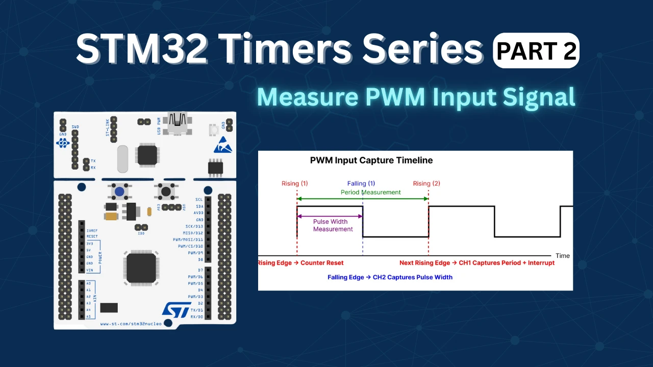
STM32 Timers (Part 2): How to Measure PWM Input Signal

STM32 Ethernet Tutorial (PART 3): UDP Client Tutorial with lwIP (Raw API)
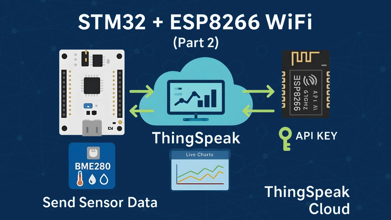
STM32 IoT with ESP8266 (Part 2): – Send Sensor Data to ThingSpeakCloud

Modbus #3.1 STM32 Master Writes Multiple Coils and Registers

Interfacing MFRC522 RFID Module with STM32 using SPI
STM32 UART using LL Drivers (Part 1): Transmit using Polling Mode

Riverdi STM32-U5 Embedded Display
STM32 WS2812 Project Download
STM32 WS2812 FAQs


Why in your code you have for-loop with 50 iterations instead of 40 (50/1.25)?
I have a question about the datasentflag. Why do we need this flag? While we wait for the flag to be set, the µC can’t do anything else. Shouldn’t that be exactly the point of using DMA, that no resources are blocked?
Ofcourse the MCU can do something else, just do not send the data to the WS2812 until the flag is set. If you have other tasks, you can wait for the flag to be set inside the ws2812_send task.
i use blue pill and rainbow effect not working at all can some body help?
It was just an example. You can write your own code to make the effect.
I had trouble getting this to work with other Clock Configuration. When using other values than 72MHz, you have to adjust the duty cycle in the code.
For example with 48MHz the ARR would be 60, resulting in this change:
WS2812_Send(void) { ... if (color & (1 << i)) { pwmData[indx] = 40; // 2/3 of ARR (60) } else { pwmData[indx] = 20; // 1/3 of ARR (60) } ... }Can anyone help me to create the code with an 8MHz system clock?
I got it working after a long period of searching …
The problem was, that traffic starts approx. 3.24 us after signal changed on bus from high to low. I added one more
for (int i=0; i<50; i++)
{
    pwmData[indx] = 0;
    indx++;
}
before the iteration loop, and it works fine!!!
Hey, good example.
Is it an option to make a tutorial of “Interface WS2812 with STM32” for the STM32duino core? I’m having trouble specifying what I need from your code and what CubeMX generates?
That would be very helpful
sorry but no. I don’t use or prefer using STM32dunio. Anyway if you are using the arduino ide, why not use the neopixel libraries?
The libraries often have poor support for STM32 or only have the F0 and F1 series up their sleeves.
I would only be interested in the HAL commands that are required for the setup of DMA and TIM.
Then use the STM HAL. Why you intend to use Arduino anyway ? Sooner or later you have to switch as you won’t find support for more complicated things in that IDE.
Hahaha I am a junior student from a certain college in China. I learned a lot from reading your article. Thank you.
Hi for people that have some issue with ram, you can save a lot by using an uint8 array on the DMA (pwmData)
For that you need to change the size of data width in the DMA IOC menu with Byte (keep HalfWord to the peripheral side
change the pwmData array by an uint8_t.
I also change the declaration of ledData and ledMod from [4] to [3], we don’t need the index in this array.
An other little modification is to remove the “+50” in the pwmData and change it with a +1 and made a delay when you finish the display. (becarefull to change the second loop in ws2812_send function)
With these modifications, I’m lowering the ram usage from 5k7 to 3k7
Trying to get this working on an existing board with STM32F103. Must use PA9 pin to drive data line, and the only unused timer I have for this is TIM8, so Channel 4 should be ok. But worse, I am using an older version of the low level library, and cannot update this. So no HAL. How do I go about simulating the pulse end callback? I’m sure it is a simple as enabling one of the interrupts and putting that code into the interrupt handler, but looking at the HAL code, there are dozens of places that call this callback, and it is not at all clear which is the right one (another reason I usually avoid HAL).
The fun challenge for me today is to control 100 WS2812 LEDs in a set of XMas lights, from an STM32F030F4. 4K RAM.
First draft hard faults as the stack descends out of RAM. LOL!
Moving all the variables to global and the RAM overflows by well over 2.4K!
I tried reducing all the datatypes as far as I could. Like storing the LEDs as 24bit packed ints in an 8bit array. MAX_LED*3 in size. That saved 100 bytes LOL
Changing the DMA array to be 8 bit (as my PWM value fits in there) even if that would work, still leaves me high and dry for around 400 bytes.
The next plan is to write the LED colors directly into the DMA array and dispose of the LED array entirely.
I can also move some stuff back onto the stack, if I can without running into the top of the heap.
I’m confused.
The pwmData array is of type uint16_t[] of size MAX_LED*24 bits + 50.
You track your uint16_t pointer location with “indx”.
However, you then cast this to a uint32_t* when you transfer it with DMA and do NOT divide indx by 2.
It seems you have N 16 bit values, but you are sending N 32bit values, which is twice the amount of data you should be. I expect you might just be getting lucky that the heap above your array is zero’d.
I expect this will also work:
HAL_TIM_PWM_Start_DMA(&htim1, TIM_CHANNEL_1, (uint32_t *)pwmData, indx/2);
you really need to look into the concept of typecasting..
For all those, who have trouble with getting HAL_TIM_PWM_PulseFinishCallback() to work – You have to Enable the interrupt from corresponding DMA channel in NVIC settings category in Cube and set its priority. Otherwise, the interrupt is not fired and the function never gets called.
Tested on STM32F411CEV6 with a single led, works beautifully 🙂
I’ve replaced the maximum brightness value (45) with this:
#define MAX_BRIGTHNESS 15

// like
if (brightness > 45)  brightness = MAX_BRIGTHNESS;

// in while loop

for (int i = 0; i < MAX_BRIGTHNESS; i++) {...}

for (int i = MAX_BRIGTHNESS; i >= 0; i--) {..}
Using the value in the two for cycles affects their duration, if you want to keep the original, use only the first “override”.
Thanks for this guide!!
did you have to download any files to make this code work. want to try it out. or just use his code directly
For everyone that doesn’t get this working; dataSentFlag should be a volatile int, not an int. Hope it helps!
This one was really obscure, thanks for the hint!
Le tutoriel est complet et fonctionne sur mes Leds RGB, j’ai juste dû adapter le format de division pour obtenir 800kHz. Parce que j’avais 48MHz pour le clock. Merci pour la vidéo et les explications sur ce site 😉
merci eric
Hey my clock 48MHz how can i format adapter division for 800kHz? (should change counter period 29?idk)
Small error:
thanks for the info. Its fixed now
Hey my clock 24MHz how can i format adapter division for 800kHz? (should change counter period 29?idk)
which clock ?
Hello. Please clarify one point. After generating the project in CubeMx, the MX_DMA_Init function looks like this:
static void MX_DMA_Init (void)
{
  / * DMA controller clock enable * /
  __HAL_RCC_DMA1_CLK_ENABLE ();
  / * DMA interrupt init * /
  / * DMA1_Stream5_IRQn interrupt configuration * /
  HAL_NVIC_SetPriority (DMA1_Stream5_IRQn, 0, 0);
  HAL_NVIC_EnableIRQ (DMA1_Stream5_IRQn);
}
Is this correct DMA initialization? It is doubtful that the settings that were made in CubeMx for DMA are not displayed in the initialization function.
not working i tried on l051 datasent while waiting every time
Good example. Have tried on F401 with ARR=105. But i don’t get HAL_TIM_PWM_PulseFinishedCallback interrupt. I will try to figure out.