
Home ▸ STM32 Tutorials ▸
Updated On: April 12, 2026
Modbus #1. Read Holding and Input Registers
I have already covered the basics of the modbus communication explaining the memory areas, their addresses and the function codes. If you don’t know about them, check out the previous tutorial.
In this tutorial I am going to assume that you already know all these things and will focus mostly on writing the code.
The modbus is a protocol and can work with any communication standard. You can use the modbus protocol with RS232, RS485 or any other standard.
Although it is widely used with the RS485 and therefor I am also going to use the RS485.
I have covered the STM32 and RS485 in the previous tutorial, and make sure you check it out. If you want to use the regular UART, you can use that too.
VIDEO TUTORIAL
You can check the video to see the complete explanation and working of this project.
The Connection
In this tutorial the STM32 will act as a master and since I don’t actually have a slave device, I am going to use a software in the computer that will make the computer to act as a slave device.
The communication will take place using the RS485 standard. STM32 is connected to the RS485 to TTL converter and the computer is connected via the RS485 to USB converter.
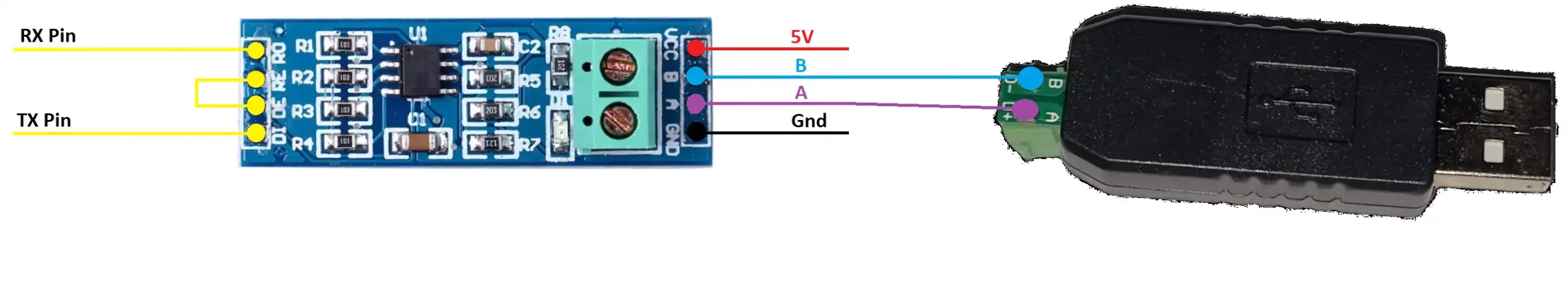
The STM32 to RS485 connection is same as explained in the previous tutorial.
Other than that we are connecting the pin A of the modules with each other and pin B with each other.
The CubeMX configuration will also remain same as what we have seen in the STM32 and RS485 tutorial.
The Slave Software
As I mentioned above I am going to use a software so the computer can act as a slave device.
The software can be downloaded from https://www.simplymodbus.ca/RTUslave.htm
Some components of the software are explained below
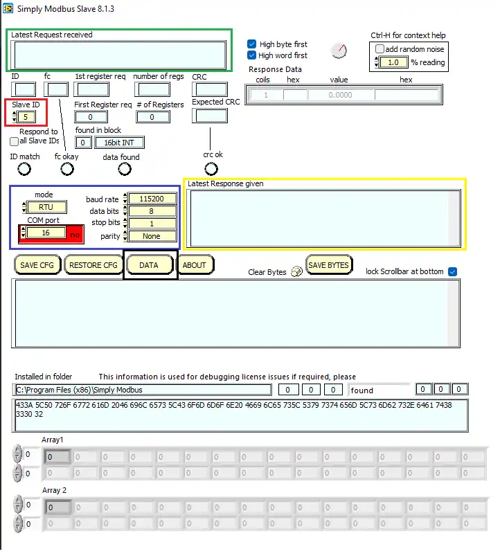
- We have the Slave ID, which we can set manually.
- The window in the Green box shows the request sent by the slave (in hex format)
- The Blue box is the Port configuration. make sure that the master and slave are configured similarly
- The yellow box shows the data sent by the slave (in hex format)
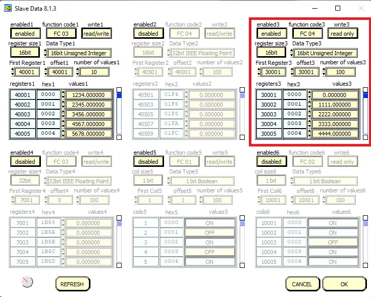
Since this is a slave device, it already have the memory areas (coils and registers). We can access them by clicking the DATA button (in Black box)
Below is the image of the registers and coils available
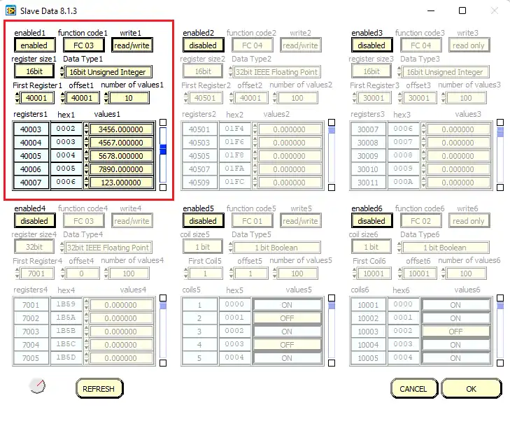
Here we are only concerned about the Red box.
- I have enabled it for the function code 3 i.e Reading Holding Registers.
- The Register size is 16 bit
- The first register address is 40001 and the offset is same as this address.
- I have stored different values at these address locations and the master is supposed to read these values.
The CODE
First We will create a function to send the data via the UART. The modbus module need to be put in the transmit mode before sending the data.
uint8_t RxData[32];
uint8_t TxData[8];
uint16_t Data[10];

void sendData (uint8_t *data)
{
	HAL_GPIO_WritePin(TX_EN_GPIO_Port, TX_EN_Pin, GPIO_PIN_SET);
	HAL_UART_Transmit(&huart1, data, 8, 1000);
	HAL_GPIO_WritePin(TX_EN_GPIO_Port,TX_EN_Pin , GPIO_PIN_RESET);
}- Here I have first defined the RX and TX buffers.
- The Data buffer is where we will receive our final values from the slave device.
- The
sendDatafunction will be used by the master to send the request to the slave device. - Here we will first pull the TX_EN pin (RE and DE Pins) High. This will put the module in the transmitter mode.
- Then we will send the data via the UART.
- After sending the data, we will again pull the TX_EN pin LOW, so to put the module in the receive mode.
Master makes the Request
Before we actually send the request to the slave device, we need to prepare our TxData buffer.
The request pattern sent by the master is shown in the picture below
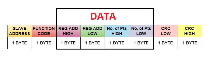
As you can see above, the master required to send 8 bytes in total. These contains:
- 1 Byte for the slave address
- 1 byte for the function code
- 2 bytes for the Starting Register Address
- 2 Bytes for the number of Registers it wants to read
- 2 bytes for the CRC
  TxData[0] = 0x05;  // slave address
  TxData[1] = 0x03;  // Function code for Read Holding Registers

  TxData[2] = 0;
  TxData[3] = 0x04;
  //The Register address will be 00000000 00000100 = 4 + 40001 = 40005

  TxData[4] = 0;
  TxData[5] = 0x05;
  // no of registers to read will be 00000000 00000101 = 5 Registers = 10 Bytes

  uint16_t crc = crc16(TxData, 6);
  TxData[6] = crc&0xFF;   // CRC LOW
  TxData[7] = (crc>>8)&0xFF;  // CRC HIGH

sendData(TxData);I have assigned the following data to TxData buffer:
- The Slave ID, which is set to 0x05.
- The function code, which is 3 for reading the holding registers
- The higher byte of the starting register address, which is 0
- The Lower byte of the starting register address, which is 4
- This will make the starting register address as 4, which combines with the offset 40001 and the final address would be 40005.
- The higher byte of the number of points, which is 0
- The Lower byte of the number of points, which is 5.
- This will make the total registers that master wants to read = 5. which will be equal to 10 bytes of data.
- The Lower byte of the CRC
- The Higher byte of the CRC
These 8 bytes will be sent by the master using the function
sendData.
Slave Responds to the Request
The master have transmitted the request. Now let’s see what is happening on the slave side.
Below is the picture of the slave device after receiving the request
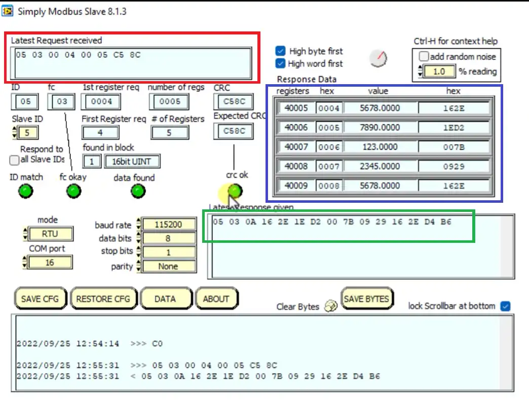
The Redd box contains the request made by the master. You can see the data is same as what we sent from the STM32.
The Blue box contains the registers, whose values was sent by the slave device.
- Notice that the register address starts from 40005, and there are total 5 registers in that box.
- The next tabs have the values which were stored in these registers, in decimal and hexadecimal formats
The Green box is the actual response sent by the slave device. It contains:
- The Slave ID of the the slave (05)
- The function code (03)
- The number of data bytes the slave is sending, 0A (10) in this case.
- The next 10 bytes are the data bytes with higher byte sent first.
- The last 2 bytes are the CRC, with lower byte sent first.
Now let’s see how the master should handle this incoming data.
Master Receives the data
Before transmitting the request we will enable the Receive interrupt for the master. Here I am using the IDLE Line Interrupt function so that the interrupt will be triggered whenever the line goes IDLE during the receive. This would mean that one set of requested data has been received.
When the interrupt is triggered, the
RxEventCallback function gets called. Here we can write the rest of the code to handle the incoming data.
// inside main function, enable the receive interrupt
HAL_UARTEx_ReceiveToIdle_IT(&huart1, RxData, 32);

// The following function is called when the interrupt gets triggered
void HAL_UARTEx_RxEventCallback(UART_HandleTypeDef *huart, uint16_t Size)
{
	Data[0] = RxData[3]<<8 | RxData[4];
	Data[1] = RxData[5]<<8 | RxData[6];
	Data[2] = RxData[7]<<8 | RxData[8];
	Data[3] = RxData[9]<<8 | RxData[10];
	Data[4] = RxData[11]<<8 | RxData[12];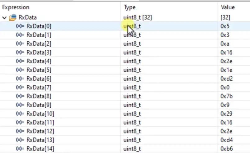
}We know that the slave is sending the 16 bit values by separating them into 2 bytes, with higher byte first. Inside the receive callback function, we will combine these data bytes and form a single 16 bit number.
- The first 3 received bytes are slave ID, Function code, and number of byes. Our actual data starts from the 4th byte.
- the RxData[3] and RxData[4] both are the values of the first register we requested.
- Since RxData[3] is the higher byte, we shift it to the left by 8 positions (<<8) and then add it with the RxData[4], the lower byte.
- This way we combine the two 8bit values into a single 16bit value.
- We do the same for the rest of the data bytes and store these values into the 16 bit array.
Reading Input Registers
The process to read the input Registers is similar to the Holding Registers. The only change is instead of using the function code 3, now we use the function code 4.
  TxData[0] = 0x05;  // slave address
  TxData[1] = 0x04;  // Function code for Read Input Registers

  TxData[2] = 0;
  TxData[3] = 0x01;
  //The Register address will be 00000000 00000001 = 1 +30001 = 30002

  TxData[4] = 0;
  TxData[5] = 0x05;
  // no of registers to read will be 00000000 00000101 = 5 Registers = 10 Bytes

  uint16_t crc = crc16(TxData, 6);
  TxData[6] = crc&0xFF;   // CRC LOW
  TxData[7] = (crc>>8)&0xFF;  // CRC HIGH

sendData(TxData);- The Slave ID, which is set to 0x05.
- The function code, which is 4 for reading the input registers
- The higher byte of the starting register address, which is 0
- The Lower byte of the starting register address, which is 1
- This will make the starting register address as 1, which combines with the offset 30001 and the final address would be 30002.
- The higher byte of the number of points, which is 0
- The Lower byte of the number of points, which is 5.
- This will make the total registers that master wants to read = 5. which will be equal to 10 bytes of data.
- The Lower byte of the CRC
- The Higher byte of the CRC
We also need to enable the function code 4 in the slave software.
Here we are only concerned about the Red box.
- I have enabled it for the function code 4 i.e Reading Input Registers.
- The Register size is 16 bit
- The first register address is 30001 and the offset is same as this address.
- I have stored different values at these address locations and the master is supposed to read these values.
Result
Holding Registers
Below are the images of the request sent by the master and the response received by the master.

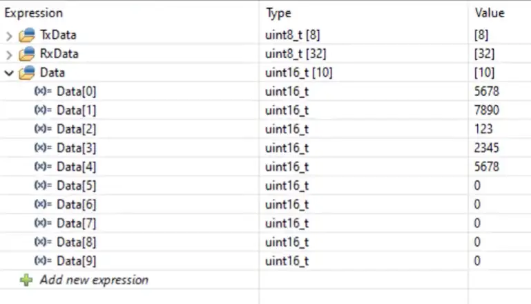
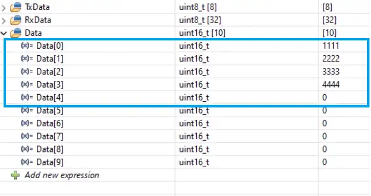
And finally we have the data array.
Input Registers
Below are the images of the request sent by the master and the response received by the master.
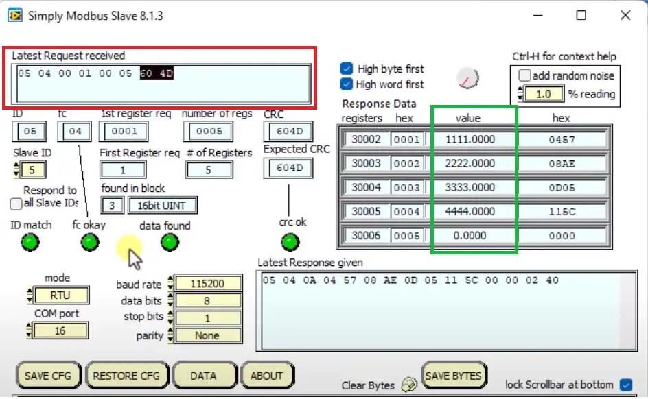
Here the Red box shows the request sent by the master and the green box contains the register values that were sent by the slave device.
On the right you can see the same values were received by the master.
STM32 Modbus RTU Tutorial Series

Modbus #2. STM32 Master Reads Coils and inputs

Modbus #3. STM32 Master Writes single Coil and Holding Register
Modbus #3.1 STM32 Master Writes Multiple Coils and Registers

Modbus #4. STM32 as Slave || Read Holding and Input Registers

Modbus #5. STM32 as Slave || Read Coils and Inputs

Modbus #6. STM32 as Slave || Write Registers

Modbus #7. STM32 as Slave || Writing Coils


from were should i download crc.h header file?
Hi Arumugam,
Any idea of make a tutorial of iec 60870-101,103,104 and iec 61850 on stm32 using official lib, i’ll be very appreciate.
many thanks!
your fans,
Junlian hu
from were should i download crc.h header file?
how did you find the crc16() ?
Its from the Modbus document. It’s shown in the video
I am facing the COM port issue in the Modbus master Master & Slave. I can see the port detail in Device Manager. But while I am trying to connect with the master/ slave using the same COM port I have seen in the device manager, it always shows in red [that means it is telling as an Invalid COM port but I had given the correct one]. Why it is showing as an invalid COM port even though I had given the correct one?