
Home ▸ STM32 Tutorials ▸
Updated On: March 23, 2026
Sending data from another task || Gauge || Animation
This is the 4th tutorial in the STM32 Touch GFX series, and today we will again see how to send the data from the MCU to the UI. In the previous tutorial I have covered how to sample from the GUI task and display the data on the UI.
In this tutorial we will see how to sample from the other tasks, and then send the data to the GUI task using the inter messaging system, which is further displayed on the UI.
I am going to use the Gauge to display the ADC value, and the animated image whose movement can be controlled by the button.
VIDEO TUTORIAL
You can check the video to see the complete explanation and working of this project.
TouchGFX Setup
Guage Setup

- I have added the gauge to the Screen.
- The name of the Gauge is “gauge1“.
- The range is set from 0 to 100 and the minimum value is set to 0.
- Rest of the configuration is kept to default.
Animated Image
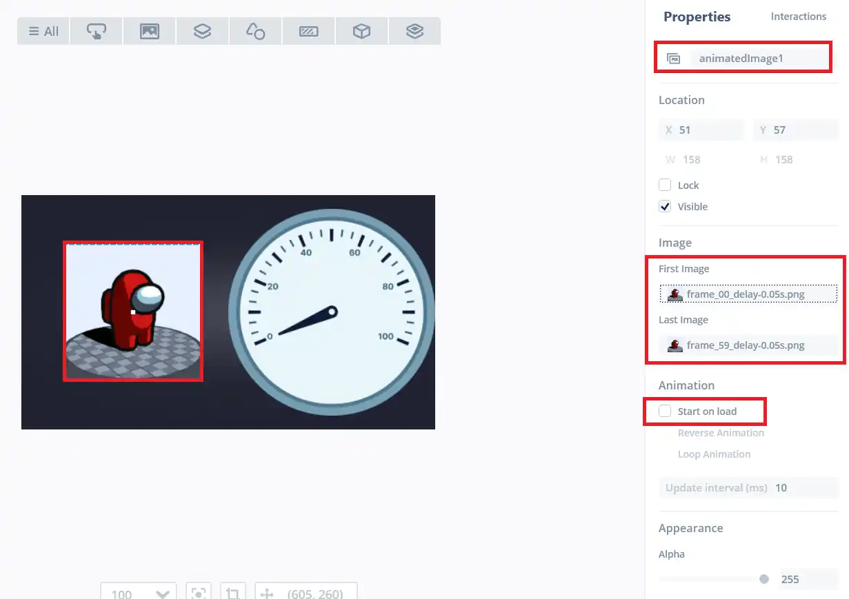
- The name of the animated image is “animatedImage1“.
- I have extracted 60 images from a gif file, so the first image is frame_00 and the last image is set to frame_59.
- I have also disabled the “Start on Load“, so that the animation does not start by its own.
- Rather I will control the start and stop using the button.
CubeMX Setup
The F750 discovery board has a user button, which is connected to the pin PI11. I have enabled the pin PI11 as the input pin.

The pin has been configured in the input mode along with the pull down. When the button is pressed this pin will be pulled high.
I am going to display the potentiometer values on the UI. This potentiometer is connected via the ADC.
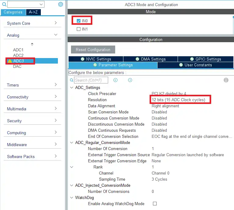
The ADC3 channel 0 is configured with 12 bit Resolution. Everything else is kept default in the ADC configuration. We will use the poll method to read the ADC values.
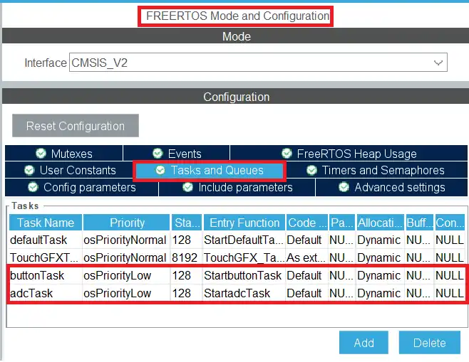
I have created 2 new tasks for the ADC and the button. Both the tasks have the low priority.
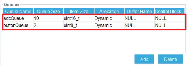
I have also created 2 queues for the inter task messaging. They will be used to send the data to the GUI task.
The adcqueue has 10 items of 16 bit data size. They will be used to store the ADC values.
The buttonqueue has 2 items of 8 bit data size.
Some Insight into the CODE
int Button_State = 0;

uint16_t ADC_Value;
int converted_val;

long map(long x, long in_min, long in_max, long out_min, long out_max)
{
  return (x - in_min) * (out_max - out_min + 1) / (in_max - in_min + 1) + out_min;
}I have created the Button_State variable to store the button state. The ADC_Value and the converted_val will be used to store the RAW ADC value and the converted value (0 – 100 Range).
The map function is used to convert the RAW ADC values to our required range (0-100 in this case).
void StartbuttonTask(void *argument)
{
  for(;;)
  {
	  Button_State = HAL_GPIO_ReadPin(GPIOI, GPIO_PIN_11);
	  osMessageQueuePut(buttonQueueHandle, &Button_State, 0, 0);
    osDelay(5);
  }

}- Here we will read the pin PI11 and store its value to the Button_State variable.
- Then send the value of the variable to the queue.
- the last 2 parameters in the osMessageQueuePut are the message priority and the timeout.
- I have kept the priority to the lowest (0), and the timeout of 0 means the message will be put to the queue only if there is some space available in the queue.
- The function will not wait for the space to become available.
- The button task will run every 5ms.
void StartadcTask(void *argument)
{
	for(;;)
	{
		HAL_ADC_Start(&hadc3);
		HAL_ADC_PollForConversion (&hadc3, 10);
		ADC_Value = HAL_ADC_GetValue (&hadc3);
		HAL_ADC_Stop (&hadc3);
		converted_val = map(ADC_Value, 0, 4095, 0, 100);

		osMessageQueuePut(adcQueueHandle, &converted_val, 0, 0);
		osDelay(10);
	}
}In the ADC task we simply read the ADC data and map it to the values between 0 to 100.
The mapped value is then sent to the adc queue.
protected:
    ModelListener* modelListener;
    uint16_t ADC_value;
bool Button_State;In the model header file I have defined the variables ADC_value and Button_State.
#ifndef SIMULATOR
#include <cmsis_os2.h>
#include "main.h"
extern "C"
{
    extern osMessageQueueId_t adcQueueHandle;
    extern osMessageQueueId_t buttonQueueHandle;
}
#endif

void Model::tick()
{
#ifndef SIMULATOR
	//Get Data from ADC Queue
	if (osMessageQueueGet(adcQueueHandle, &ADC_value, 0U, 0) == osOK)
	{
		modelListener->setADC(ADC_value);  // send data to presenter
	}

	// Get data from Button Queue
	static int button;
	if (osMessageQueueGet(buttonQueueHandle, &button, 0U, 0) == osOK)
	{
		if (button) Button_State = true;
		else Button_State = false;
		modelListener->setAnimation (Button_State);
	}
#endif
}Here we will first include the RTOS header file and the main header file. We also need to define the queues externally.
- Now in the tick function we will first get the value from the adc queue, and store it in the ADC_value variable.
- The the modelListener will call the function setADC in the presenter and send the ADC_value as the parameter to this function.
- Similarly we will get the button state from the button queue and store it in the variable Button_State.
- Again the modelListener will call the function setAnimation in the presenter and send the button state as the parameter of this function.
void Screen1Presenter::setADC(int val)
{
	view.setADC (val);
}

void Screen1Presenter::setAnimation (bool state)
{
	view.setAnimation (state);
}In the presenter source file, we will call the same functions in the view.
void Screen1View::setADC(int val)
{
	gauge1.setValue(val);
	gauge1.invalidate();
}

void Screen1View::setAnimation (bool state)
{
	if (!(animatedImage1.isAnimatedImageRunning()))
	{
		if (state == true)
		{
			animatedImage1.startAnimation(false, false, true);  // rev, should reset, loop
		}
	}

	else if ((animatedImage1.isAnimatedImageRunning()))
	{
		if (state == false)
		{
			animatedImage1.pauseAnimation ();
		}
	}

}In the view source file we will finally write the functions to display the data on the UI.
- In the setADC function, we will set the value (received from the presenter) to the Gauge.
- Then invalidate the gauge so that the update can take effect.
In the setAnimation function we will first check if the animation is running or not.
- If the animation is not running, and the state is true (button is pressed), then we will start the animation.
- startAnimation takes the following parameters
- @rev Defines if the animation should be performed in reverse order. I have set it to false
- @reset Defines if the animation should reset and start from the first (or last if reverse order) bitmap. It is set to false as I don’t want the animation to reset whenever the button is pressed.
- @loop Defines if the animation should loop or do a single animation. It is set to true because I want the animation to keep looping when the button is pressed.
- If the animation is already running and the button is released, we will pause the animation.
- The function pauseAnimation() is used to pause the animation.
Result
Below the gif shows the animated image and the gauge working.
STM32 TouchGFX Tutorial Series

TouchGFX #2. How to use TextArea and Wildcards

TouchGFX #3. Sending data to UI || MVP

TouchGFX #5. Data from UART to UI

TouchGFX #6. How to Build a Multiscreen Project

TouchGFX #7. How to implement on screen keyboard

TouchGFX #8. Send data from GUI to MCU

Subscribe
Login
0 Comments
Newest
