
Home ▸ STM32 Tutorials ▸
Updated On: March 23, 2026
QSPI & External Loader in H750
This is the 10th tutorial in the W25Q Flash series, and today we will see how to use the interface the W25Q external flash memory using the Quad SPI peripheral on an H7 based MCU. We will also see how to create an External Loader and how to relocate the data to the external flash using this loader.
I have also covered similar tutorials in the past but some of you still had some issues with QuadSPI on cortex M7 devices. This is why this tutorial will cover everything from interfacing the W25Q flash memory to creating an external loader.
VIDEO TUTORIAL
You can check the video to see the complete explanation and working of this project.
Connection
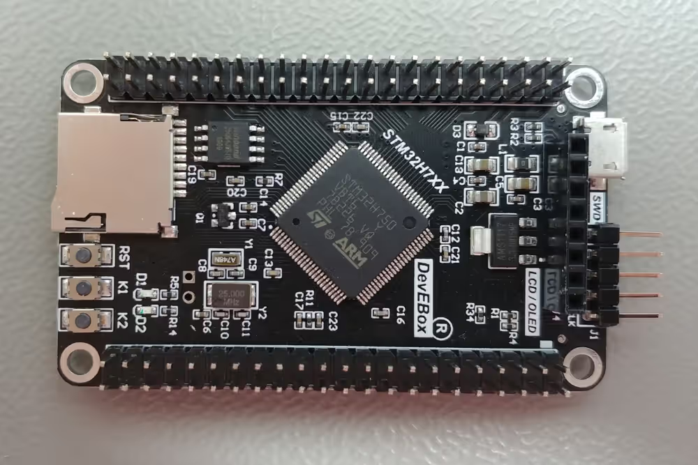
I am using the STM32H750 custom development board and it has the W25Q64 flash memory soldered on it. You can see the image of the board shown below.
The schematic of this board shows how the flash memory is connected to the MCU.
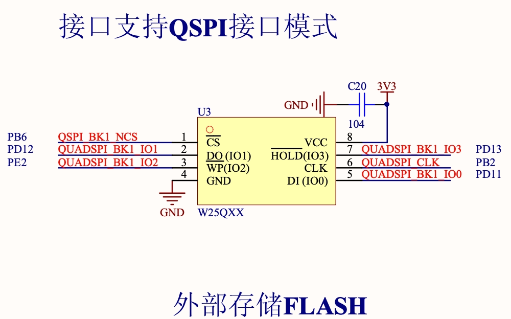
We will set up the cubeMX according to this diagram.
CubeMX Configuration
The clock is configured as shown below.
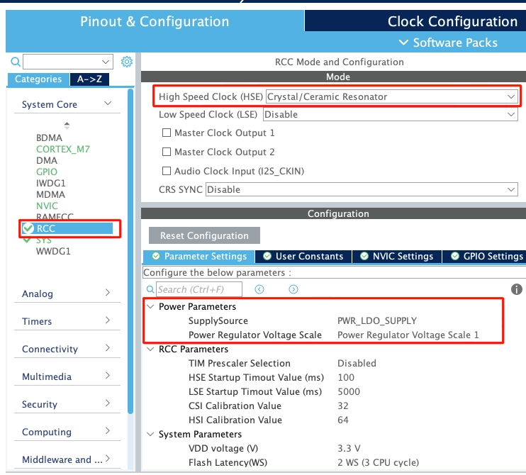
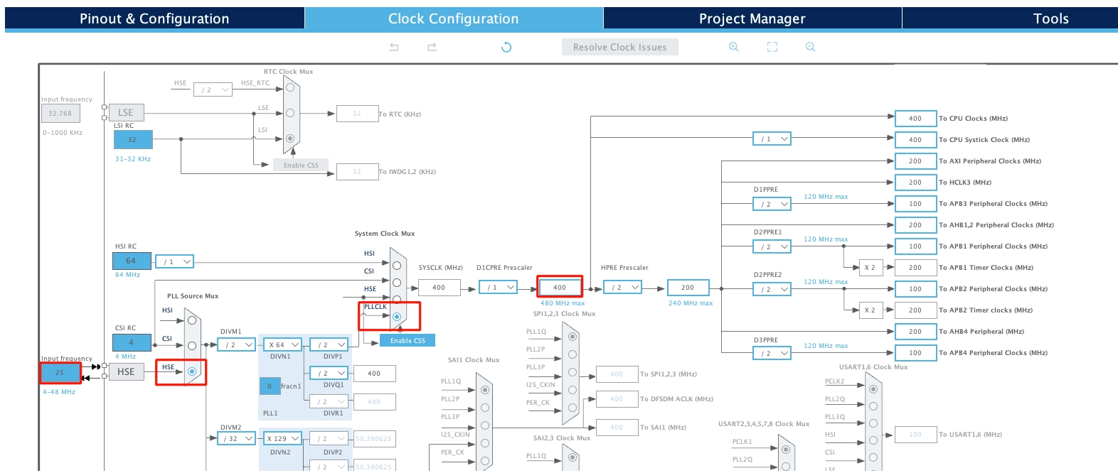
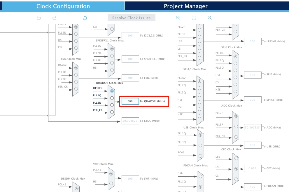
I have selected the external crystal for the clock. The board has 25MHz crystal on it and the board is configured to run at 400MHz clock. With this configuration the QuadSPI clock is running at 200MHz.
We will now configure the QuadSPI peripheral. Below is the image showing the QuadSPI configuration.
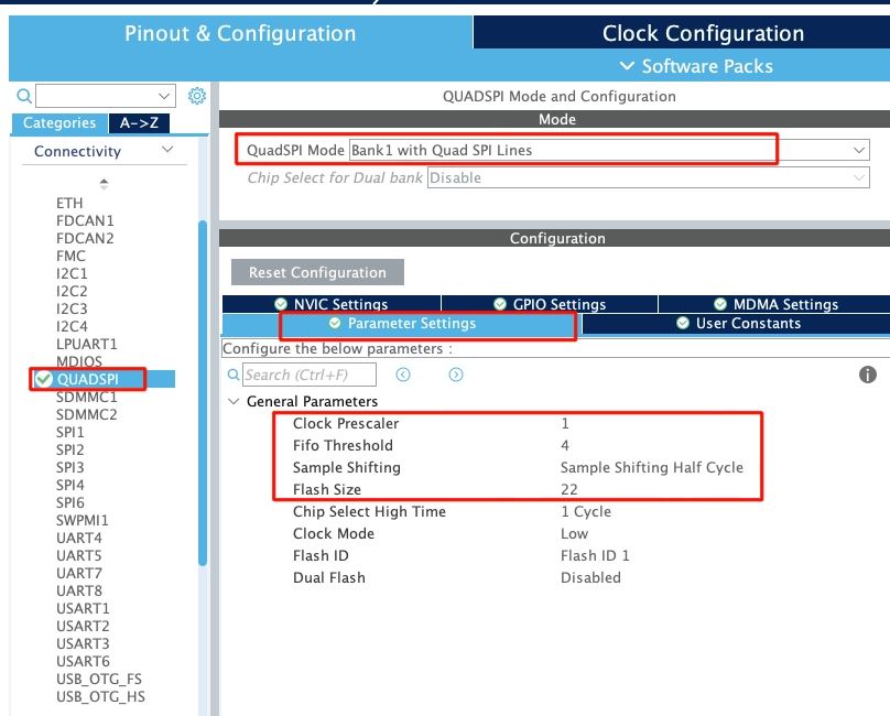
- The Prescaler of 1 (actually the value 2) will reduce the QuadSPI clock to 100MHz. (200MHz/2)
- Set the fifo threshold to 4, and the sample shifting to half cycle.
The flash size is based on the size of the external flash you are using. It can be calculated using the formula below.
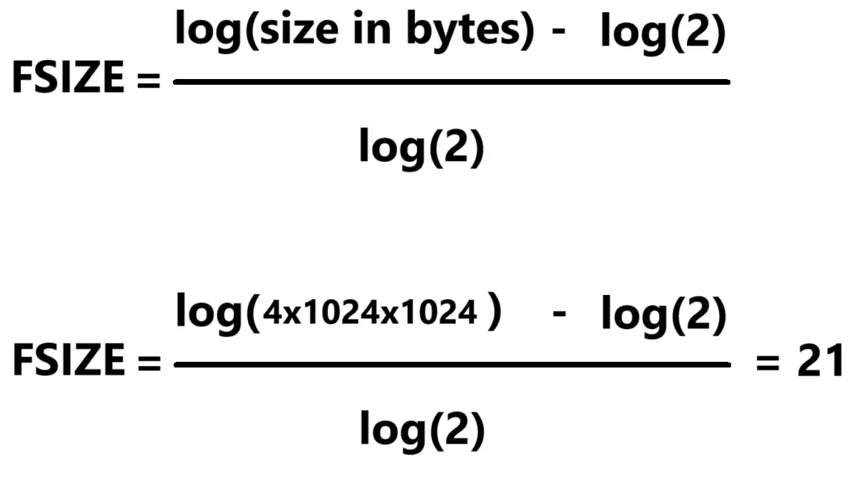
The board has the W25Q64 flash which is 8MB in size. As per the calculation, the Flash size will be 22.
The pins are configured as per the schematic, as I mentioned in the beginning of this tutorial.
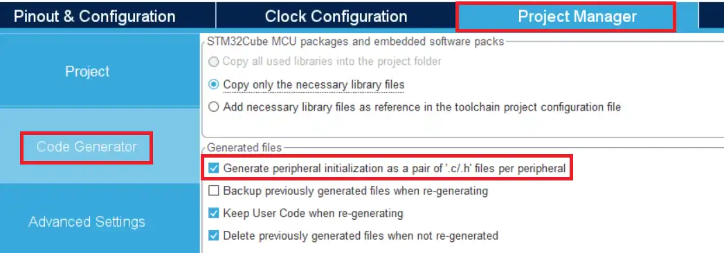
Also make sure to check the box shown below to generate the separate files for the peripherals.
Some Additional Process
I have modified the ST’s quadSPI library files so that they can be used with the W25Q series nor flash memories. You can get the files by downloading the project at the end of this post.
You need to copy the code inside the /* USER CODE BEGIN 0 */ and /* USER CODE END 0 */ in the respective position in the quadspi.c file.
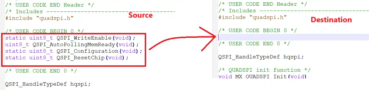
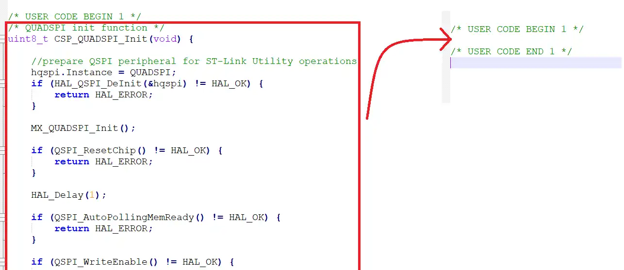
Similarly copy the code inside the /* USER CODE BEGIN 1 */ and /* USER CODE END 1 */ to the respective position.
Also replace the content of the quadspi.h file.
Since we are using W25Q64, we need to change the MEMORY FLASH SIZE to 8MB.
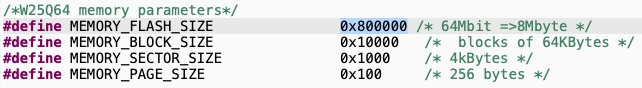
I have defined the MEMORY SIZE of 8MB for the W25Q64.
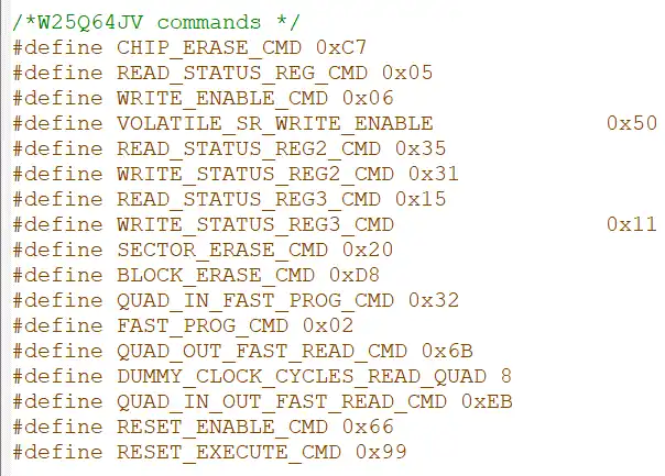
Also cross check the commands defined with the datasheet of the memory.
Test the Flash Memory
We will test the flash memory before we can proceed with the external loader. We can get test code from the ST’s github page itself.
/* USER CODE BEGIN 2 */

uint8_t buffer_test[MEMORY_SECTOR_SIZE];
uint32_t var = 0;

CSP_QUADSPI_Init();

for (var = 0; var < MEMORY_SECTOR_SIZE; var++) {
    buffer_test[var] = (var & 0xff);
}

for (var = 0; var < SECTORS_COUNT; var++) {

    if (CSP_QSPI_EraseSector(var * MEMORY_SECTOR_SIZE,
                             (var + 1) * MEMORY_SECTOR_SIZE - 1) != HAL_OK) {

        while (1)
            ;  //breakpoint - error detected
    }

    if (CSP_QSPI_WriteMemory(buffer_test, var * MEMORY_SECTOR_SIZE, sizeof(buffer_test)) != HAL_OK) {

        while (1)
            ;  //breakpoint - error detected
    }

}

if (CSP_QSPI_EnableMemoryMappedMode() != HAL_OK) {

    while (1)
        ; //breakpoint - error detected
}

for (var = 0; var < SECTORS_COUNT; var++) {
    if (memcmp(buffer_test,
               (uint8_t*) (0x90000000 + var * MEMORY_SECTOR_SIZE),
               MEMORY_SECTOR_SIZE) != HAL_OK) {
        while (1)
            ;  //breakpoint - error detected - otherwise QSPI works properly
    }
}

/* USER CODE END 2 */Here we first initialise the QuadSPI memory, then erase few sectors and write the data into those sectors. Then enable the memory mapped mode to map the external flash as internal memory. Finally compare the data in the external memory to the data we wrote. If everything works well, the control will not enter any of the infinite loops in these processes.
Below is the image of the debugger showing the result of the above code.
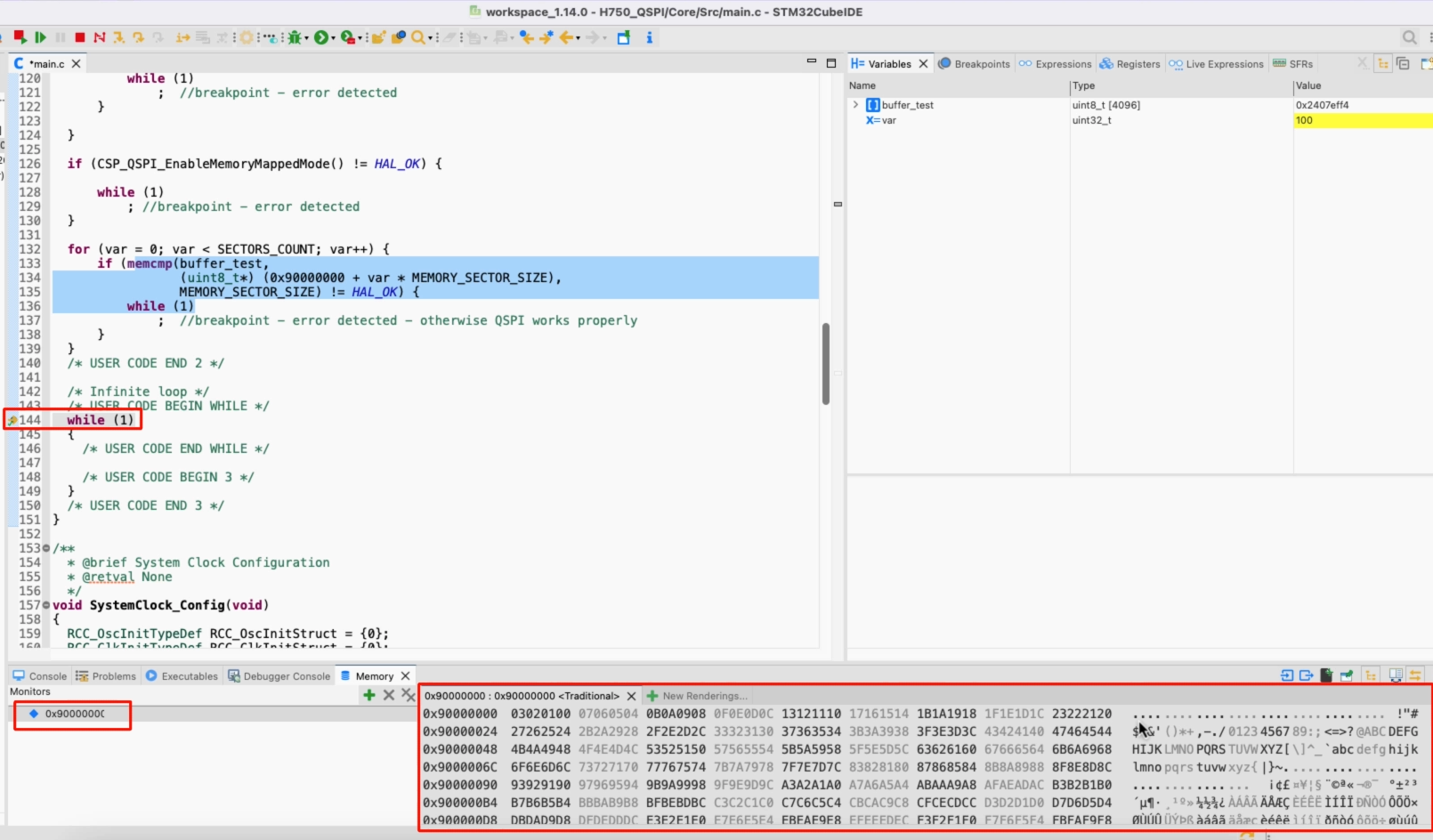
As you can see in the image above, we hit the breakpoint set at the while loop. This means all the functions were processed successfully and the code does not stuck in between.
Also note the data in the memory viewer. Since the memory mapped mode is enabled, we can view the external memory in the memory viewer, just like we can view the internal memories. We have he data at this location and it is same data that we wrote during the testing.
The test for the external flash memory using the QuadSPI peripheral is a success. We can now proceed to create the external loader for this board.
Create the External Loader
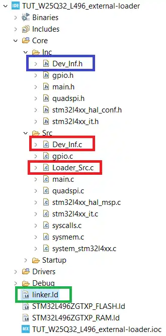
We need to first copy certain files from the ST’s folder into our project. Open the ST’s folder -> Loader_files. If you have H7 device, open the respective folder, otherwise open the Other devices folder.

Now copy the ***.c files in the src directory of the project, ***.h file in the inc directory and the linker file in the main project folder. The final project structure is shown below.
You can set the Loader name in the Dev_inf.c file as shown below. Also make sure to cross check the QSPI start Address (0x90000000 in this case) with the reference manual of your MCU.
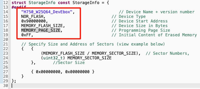
Other details like MEMORY_FLASH_SIZE, PAGE_SIZE, SECTOR_SIZE are fetched from the QuadSPI.h file we defied in the previous tutorial.
Now we need to set the linker file for the project.
Go to Project Properties -> C/C++ Build -> Settings -> MCU GCC Linker -> General. Here change the Linker Script to the Linker file we copied.
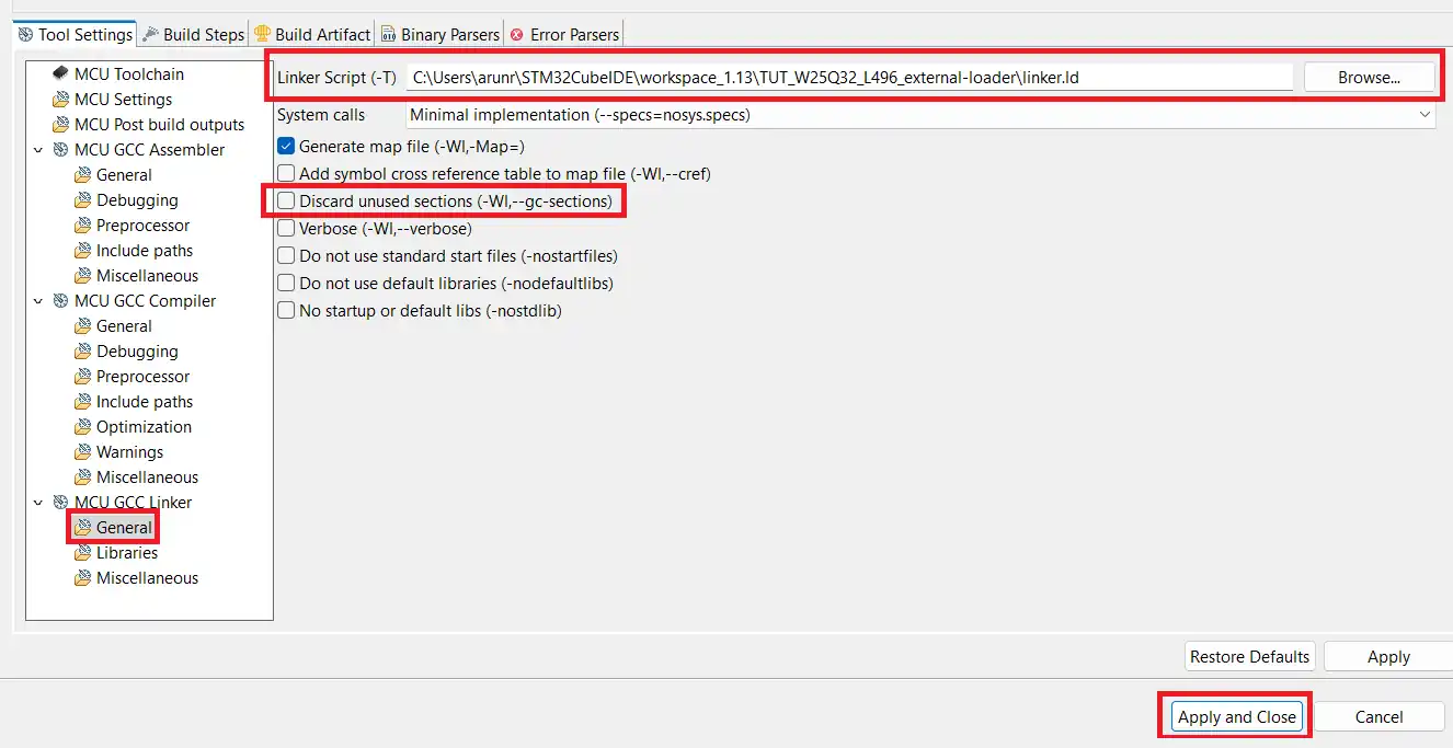
As shown above i have changed the Linker Script to the linker.ld file. Also make sure to uncheck the Discard unused sections. After making the changes, click on Apply and Close.
We also need to copy the post build command to the Build Steps tab as shown below.
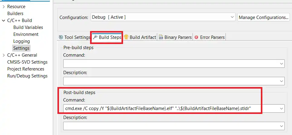
The command is cmd.exe /C copy /Y “${BuildArtifactFileBaseName}.elf” “..\${BuildArtifactFileBaseName}.stldr”. It will copy the stldr file (loader) to the main project folder.
Now build the code, and you should see the Loader file (***.stldr) in the main project folder itself. This is shown below.
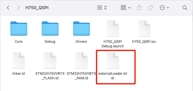
Here I have changed the name of the file to “externalLoader.stldr”.
Test the Loader
We can use the external loader to debug the external memory in cubeIDE.
Basically we will reallocate a data buffer to the external memory. This data buffer can be an image file, or an audio or video file, as it takes a lot of space in the internal flash memory. We need to initialise the QSPI memory in the memory mapped mode, and the external loader is needed to reallocate the buffer.
The main file
Below is the code needed to implement in the main file.
const __attribute__((section(".extFlash"))) uint8_t buf[] = "Hello world from H750 QSPI";

uint8_t Readbuf[40];Here I am allocating the buf to a specific section (extflash). We will define this section in the flash script file.
  /* USER CODE BEGIN 2 */

  if (CSP_QUADSPI_Init() != HAL_OK) Error_Handler();

  if (CSP_QSPI_EnableMemoryMappedMode() != HAL_OK) Error_Handler();

  memcpy(Readbuf, (uint8_t *) 0x90000000, 27);

/* USER CODE END 2 */In the main function, we will initialise the QSPI and enable the memory mapped mode. Then we will read the data from the QSPI location 0x90000000. If the reallocation is successful, we should see the data from buf into the Readbuf.
Note that we are not performing any write to the QSPI memory. We are simply reallocating the data buffer to the external memory.
Flash script
Define the QSPI memory in the flash script file as shown below.
MEMORY
{
  FLASH (rx)     : ORIGIN = 0x08000000, LENGTH = 128K
  DTCMRAM (xrw)  : ORIGIN = 0x20000000, LENGTH = 128K
  RAM_D1 (xrw)   : ORIGIN = 0x24000000, LENGTH = 512K
  RAM_D2 (xrw)   : ORIGIN = 0x30000000, LENGTH = 288K
  RAM_D3 (xrw)   : ORIGIN = 0x38000000, LENGTH = 64K
  ITCMRAM (xrw)  : ORIGIN = 0x00000000, LENGTH = 64K
  QSPI (rx)     : ORIGIN = 0x90000000, LENGTH = 8M
}Here I have added the last line in the MEMORY definition. The QSPI memory starts at 0x90000000 and has the size of 8 Megabytes.
Now add a new section towards the end of the memory and define the extflash section in it.
   .extFlash :
  {
    *(.extFlash)
} > QSPI We reallocated the buf to the extflash section, so it needed to be defined in the flash script file.
Debugger
The reallocation can not happen until we use the external loader, so we will now add the loader to the debug configuration.
Open the debug configuration, goto the debugger tab, scroll down to external loaders, and click add.
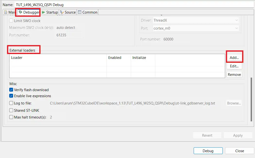
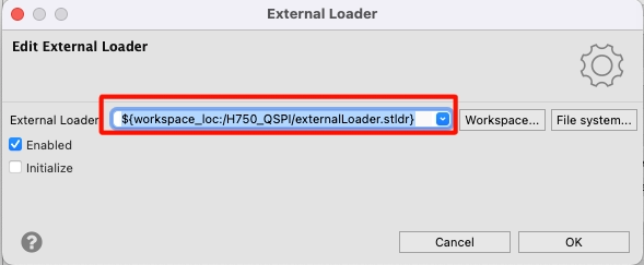
Now browse the external loader we created, and debug the project.
Result
Below is the image showing the result of the above code.
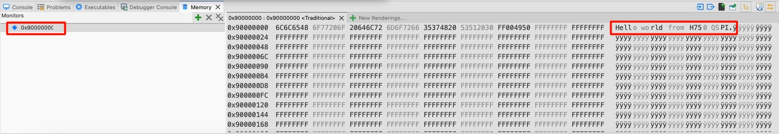
You can see the memory location (0x90000000) contains the same data that we relocated to it. We achieved the result without even performing a write operation to the QSPI memory. This means the relocation of the data works as the data has been relocated to the QSPI memory.
We can use it to relocate large files like images, audio files, or even the video files.
STM32 W25Q Flash Tutorials Series
W25Q Flash Series Part 5 – how to update sectors

W25Q Flash Series Part 6 – Integers floats and 32bit Data

W25Q Flash Series Part 7 – QUADSPI Write, Read, Memory Mapped mode

W25Q Flash Series Part 8 – QUADSPI External Loader
W25Q Flash Series Part 9 – SPI Flash Loader
W25Q Flash Series Part 11 – Xecute In Place (XIP)
LVGL on STM32 || PART7 || Load LVGL from Ext Flash


hello! i am making an external loader to write lvgl image to flash w25q128 connected to stm32h723zgt6 at ospi1 port running quad mode. following this 10th example everything runs correctly but at the last step which is real debugging on the chip it reports memory address error. do you have any solution for this case running at ospi port? thanks a lot!!!!
What cube programmer version are you use? I have issue with the newest but with 2.15 working.
What kind of issues ?
Hello Controllers Tech, I am using the external loader for uploading the touchgfx images to the core mcu using the external nor flash, i followed your tutorial 10 and 11 https://controllerstech.com/w25q-flash-series-part-10-qspi-ext-loader-in-h750/ for creating a loader file, in your video you have not enabled the check box of “initialize”. Kindly let me know the reason for that, as we need to dump the images we need to initialise. on initializing the both the HAL_Delay() is not working. My code is getting stuck inside this function HAL_getTick() function def. inside the “stm32l4xx_hal.c“.
Maybe you did not follow https://controllerstech.com/w25q-flash-series-part-11-xip/#:~:text=Now%20open%20the%20System_stm32H7xx.c