
Home ▸ STM32 Tutorials ▸
Updated On: September 14, 2025
STM32 as I2C SLAVE || PART 5
This is the 5th tutorial in the STM32 I2C Slave series. This tutorial will cover how the master can write some data into the memory of the slave device. We will define some memory location for the slave device and treat them as different registers.
uint8_t I2C_REGISTERS[10] = {0,0,0,0,0,0,0,0,0,0};The master can write a byte to a single register or multiple bytes starting from a particular register.
We will continue this tutorial from where we left in the PART3 of this series. Most of the code will remain exactly the same as the PART3 and we will just add the processing of data into it.
VIDEO TUTORIAL
You can check the video to see the complete explanation and working of this project.
CubeMX Setup
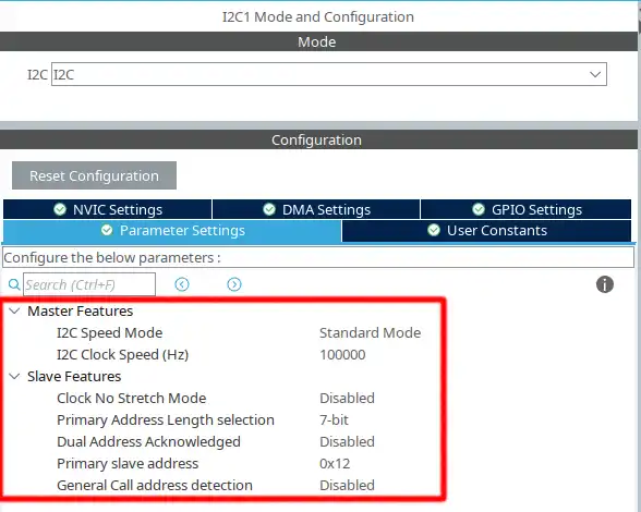
Above shown is the configuration for the I2C1
- The mode is set as standard mode with the clock speed of 100000 Hz
- The
Clock No Stretch Modeis disabled, that means the Clock stretching is enabled. - The Primary slave address length is 7 bit and the address for the device is set to 0x12 (7 bit)
- The STM32 I2C is capable of acting as 2 different slave devices with 2 different addresses, but it is disabled, and there will be only 1 slave.
- We will cover more about Clock stretching and General call address detection in the upcoming tutorials.
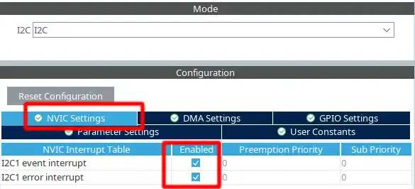
We also need to enable the Event Interrupt and Error Interrupt in the NVIC Tab
The pinout is shown below
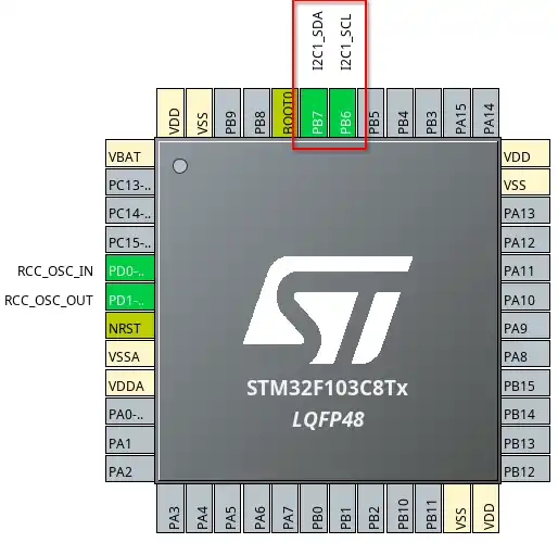
The pin PB6 is the SCL (Clock) pin and must be connectde to the SCL pin of the master. The pin PB7 is the SDA (Data) pin and must be connected to the SDA of the master. If you are connecting 2 similar MCUs, you can connect the same pins together. For eg- PB6 -> PB6 and PB7 -> PB7.
Some Insight into the CODE
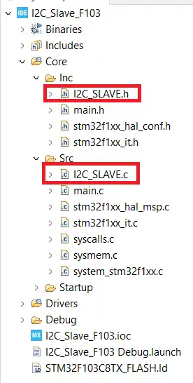
We created separate file to write the source code for the I2C Slave. We will modify these files again.
The i2c_slave.c is in the src folder and the i2c_slave.h is in the inc folder. The image is shown below.
The main function remains the same. We put the I2C in the Listen mode.
HAL_I2C_EnableListen_IT(&hi2c1);Address Callback
The changes are going to be made in the slave source file. They are as follows
int is_first_recvd = 0;

void HAL_I2C_AddrCallback(I2C_HandleTypeDef *hi2c, uint8_t TransferDirection, uint16_t AddrMatchCode)
{
	if (TransferDirection == I2C_DIRECTION_TRANSMIT)  // if the master wants to transmit the data
	{
		rxcount = 0;
		countAddr++;
		// receive using sequential function.
		HAL_I2C_Slave_Sequential_Receive_IT(hi2c, RxData+rxcount, 1, I2C_FIRST_FRAME);
	}
}The Address Callback is called when the address sent by master matches with the slave address.
- Here we will check if the Master wants to Write the data or Read it, using the variable TransferDirection.
- If the Master wants to write (Transmit) the data, we will start receiving the data.
- The variable rxcount keeps track of the buffer position, so we will reset it to 0. This way the new data will start storing from the beginning of the RxData buffer.
- The slave will receive only 1 byte in the interrupt mode, and the Option is set as I2C_FIRST_FRAME.
- The FIRST FRAME option allow to manage a sequence with start condition, and is generally used when the slave receives the fresh new byte.
Once the slave successfully receives 1 byte data, the Rx complete callback will be called.
Receive Callback
void HAL_I2C_SlaveRxCpltCallback(I2C_HandleTypeDef *hi2c)
{
	rxcount++;
	if (rxcount < RxSIZE)
	{
		if (rxcount == RxSIZE-1)
		{
			HAL_I2C_Slave_Sequential_Receive_IT(hi2c, RxData+rxcount, 1, I2C_LAST_FRAME);
		}
		else
		{
			HAL_I2C_Slave_Sequential_Receive_IT(hi2c, RxData+rxcount, 1, I2C_NEXT_FRAME);
		}
	}

	if (rxcount == RxSIZE)
	{
		process_data();
	}

}- In the Rx complete callback we increment the rxcount variable, so that the new data to be received can be stored at a new position in the buffer.
- Since we don’t want to receive more data than the RxSIZE, the reception will only continue if the rxcount is less than the RxSIZE.
- As long as the buffer has space in it, the slave will continue receiving 1 bye of data using the option I2C_NEXT _FRAME.
- I2C_NEXT_FRAME implies that the slave is receiving this byte and is also ready to receive the next byte.
- If the rxcount has reached a value that is 1 less than the RxSIZE (this means that there is only 1 space available in the buffer), we will receive 1 byte of data with the option set to I2C_LAST_FRAME.
- I2C_LAST_FRAME is used to indicate that the slave does not wants to receive anymore data after this. Now it’s upto the master, whether it wants to continue the transmission or end it. But the slave will start sending a NACK response after this reception is complete.
Basically the slave wants to end the transmission after receiving “RxSIZE” bytes of data. Also remember that even after receiving with the option of I2C_LAST_FRAME, the Rx complete callback will be called. So we need to make sure that the slave does not start the reception again. This is why the entire receving sequence is safeguarded inside the if (rxcount < RxSIZE) condition.
If the master sends more data than the RxSIZE, the slave will start sending the NACK response.
Finally if the rxcount is equal to RxSIZE (that means the RxData buffer is full), we will start processing the received data.
Error Callback
I mentioned earlier that the processing will begin when the slave has received all the data (RxSIZE) or if the master ends the transmission before that. In the latter case, an error is triggerd in the slave device. This is because it was expecting more data from the master, but the master sent a stop condition instead.
The Acknowledgement Failure error gets triggerd in the above scenario. We will use this error as an indication that the master has stopped the transmission.
void HAL_I2C_ErrorCallback(I2C_HandleTypeDef *hi2c)
{
	counterror++;
	uint32_t errorcode = HAL_I2C_GetError(hi2c);
	if (errorcode == 4)  // AF error
	{
		process_data();
	}
	HAL_I2C_EnableListen_IT(hi2c);
}- In the error callback function, we will first check the errorcode.
- If the errorcode is 4 (AF Error), indicating that the master has sent a stop condition, we will start processing the data.
Whether the processing data has been called by the “error callback” or the “Rx complete callback”, the valid data is always between RxData[0] and RxData[rxcount-1].
Processing Data
The processing request can be made by either the RX complete callback or the error callback. In terms of this particular tutorial, the processing data simply means that we have to update the registers database with the values sent by the master.
The STM32 master can make the request as follows:
HAL_I2C_Mem_Write(&hi2c1, DevAddress, 7, 1, TxData, 2, 1000); // write 2 bytes starting from register 7Using the function Mem_Write, the master is requesting to write 2 bytes stored in the TxData buffer into the slave registers, starting from the address 7.
Here @7 is the register address, @1 is the size of register address, @TxData is the buffer to send and @2 is the number of bytes to send.
The slave will proceed this request in the following manner.
void process_data (void)
{
	int startREG = RxData[0];
	int numREG = rxcount-1;
	int endREG = startREG + numREG -1;
	if (endREG>9)
	{
		Error_Handler();
	}

	int indx = 1;
	for (int i=0; i<numREG; i++)
	{
		I2C_REGISTERS[startREG++] = RxData[indx++];
	}
}When the slave receives the data from the master, the register address gets stored in the RxData[0] position and the main data is stored starting from the RxData[1].
- We will first retrieve the address of the register from the first byte of the RX buffer (RxData[0[).
- Then calculate the number of registers the master wants to write. This is equal to the rxcount-1. The variable rxcount holds the number of total bytes received by the slave. This includes the address byte also. So the remaining bytes (rxcount-1) is equal to the main data in the RX buffer.
- Using the start register and the number of registers, we calculate the address of the end register. The -1 is used because the register address starts from 0.
For example, if the start register is 7 and number of registers are 2, then the end register will be 7+2-1 = 8. So the master will write the data to the register 7 and register 8. - Since we have the database for only 10 registers (0-9), if the end register exceeds 9 we will call the error handler.
- If everything is fine, define an indx variable with the value 1. This will be used to keep track of the position inside the RxData buffer. It is currently set to 1 because the main data starts from the position 1.
- Now we will read the data from the RxData Register and store it in the I2C Register database. The loop runs as many times as the number of registers the master is writing.
- The indx variable and the startREG variable is incremented so that the position is updated for both the memory locations.
Result
Below is the image showing the master sending the data, the slave receiving the data in the RxData buffer and the I2C REGISTERS getting updated.
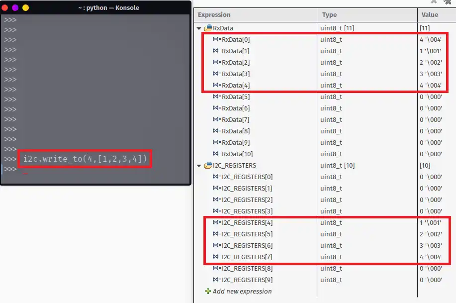
As shown in the image above, the master used the command i2c.write_to to write 4 bytes starting from the address 4.
The slave receives 5 bytes in the RxData buffer with the first byte being the Register address and the remaining 4 are the main data bytes.
Finally the I2C_REGISTERS database is updated, starting from the REGISTER[4].
STM32 I2C Slave Tutorial Series

STM32 as I2C SLAVE || PART 2

STM32 as I2C SLAVE || PART 3

STM32 as I2C SLAVE || PART 4

STM32 as I2C SLAVE || PART 6

STM32 as I2C SLAVE || PART 7

Subscribe
Login
0 Comments
Newest
