BLDC Motor Control with STM32 using PWM and ESC
Brushless DC (BLDC) motors are widely used in drones, robotics, and industrial automation because of their efficiency, reliability, and precise speed control. In this tutorial, we will learn how to interface a BLDC motor with an STM32 microcontroller using PWM signals. By combining an STM32 timer with an Electronic Speed Controller (ESC), you can easily manage motor speed and direction while keeping the system stable. This guide also covers CubeMX configuration, clock setup, ADC with DMA, and complete HAL code examples, making it easy to adapt to your own STM32 projects.
We’ll cover everything step by step: the wiring of the ESC and motor, CubeMX configuration for PWM and ADC, generating the correct duty cycle, and writing code to adjust motor speed with a potentiometer. This approach gives you hands-on experience with STM32 timers, ADC with DMA, and practical PWM control. By the end, you’ll not only have a working BLDC motor setup but also gain deeper knowledge of STM32 peripherals.
STM32 BLDC Motor Video Tutorial
Prefer video? Watch the same wiring, CubeMX setup, and code in action.
Watch the VideoWhat is a BLDC Motor and Why Use it with STM32?
A Brushless DC Motor (BLDC) is an electronically commutated motor that uses a controller instead of brushes for switching. This makes it more durable, efficient, and quiet compared to brushed motors. With an Electronic Speed Controller (ESC), the BLDC motor can be easily driven by PWM signals from an STM32 timer. This makes it a perfect choice for projects that require high precision, such as drones, robotics arms, and automation systems.
Key Points
- Efficient and reliable due to brushless design.
- Controlled via PWM signals from STM32 timers.
- Requires an ESC for smooth operation and speed regulation.
- Suitable for variable speed control using ADC + potentiometer.
- Works seamlessly with CubeMX and HAL libraries.
Applications
- Drones and quadcopters
- Robotics projects (arms, rovers, manipulators)
- Electric vehicles and e-bikes
- Industrial automation and CNC machines
- Research and educational projects
STM32 BLDC Motor Project Requirements
Here are the components used in this project. Some links are affiliate links that help support this work at no extra cost to you:
- STM32 Development Board (STM32F103C8T6)
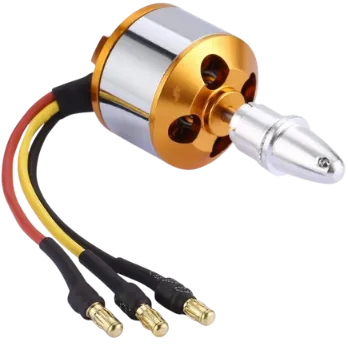
- 1400KV BLDC Motor
- 30A Electronic Speed Controller (ESC)
- 10kΩ Potentiometer (for speed control via ADC)
- LiPo Battery (11.1V / 3S)
- Jumper Wires and Breadboard
BLDC Motor ESC and STM32 Wiring Diagram
The image below shows the complete wiring between the BLDC motor, 30A ESC, LiPo battery, and the STM32 (including PA8 PWM signal and PA0 potentiometer input).
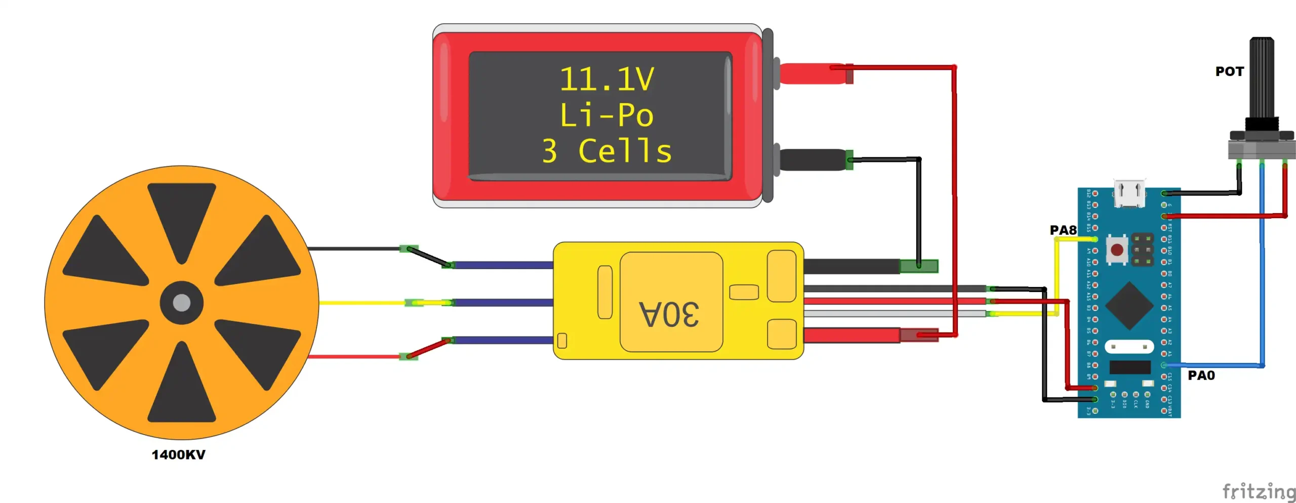
This connection diagram represents the signal flow: the ESC takes battery power, drives the BLDC motor phases, powers the MCU’s 5V rail via BEC, and receives the PWM command from STM32 PA8. The potentiometer feeds an analog voltage to PA0 for speed control via ADC + DMA.
The ESC gets the supply from the battery and powers both, the motor and the controller. The 2 side wires from the ESC can be connected to motor in either direction, but the center wire must be connected to the center wire of the motor.
The ESC also have a 3 pin wire, which can be connected to the controller, STM32 in this case. The Red wire is the VCC, By combining with the ground, it can supply 5 volts to the MCU.
The signal wire is connected to the pin PA8 of the STM32, which is basically the PWM output pin, and will be used to control the speed of the motor.
I have also connected the potentiometer to the pin PA0 of the controller. The potentiometer values will be read using the ADC, and we will use this potentiometer to control the speed of the motor.
STM32 CubeMX Configuration
In this section, we will configure the STM32 using CubeMX. The setup includes STM32 clock configuration, ADC setup with DMA, and PWM timer configuration for the BLCD Motor.
STM32 Clock Configuration
The image below shows the clock setup for this project.
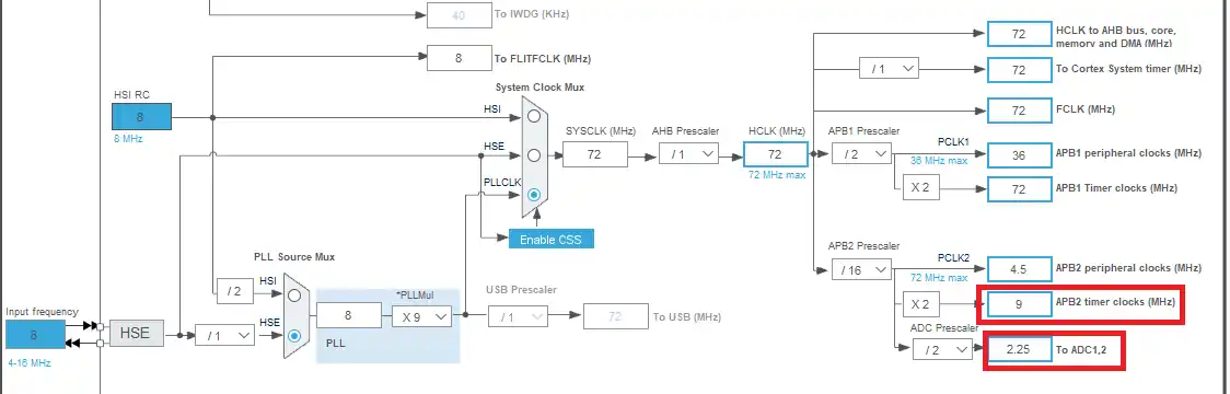
This configuration uses the external 8 MHz crystal oscillator and sets the system clock to the maximum 72 MHz using PLL. I have reduced the ADC clock to around 2MHz, so as to avoid overly high interrupt rates. The APB2 timer clock runs at 9 MHz, which feeds TIM1 for generating the PWM signals.
ADC Configuration for Potentiometer
The image below shows the ADC1 configuration with channel 0 selected for the potentiometer input.
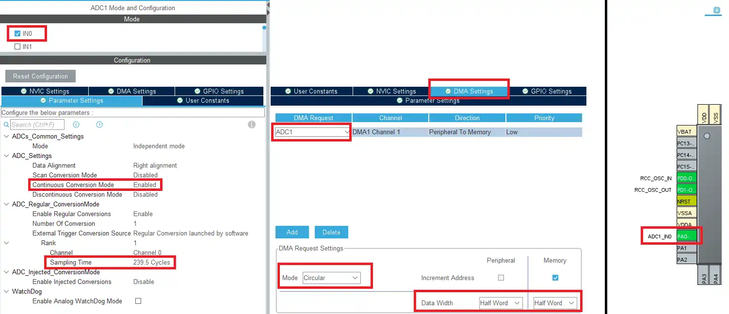
The ADC is configured in continuous conversion mode on channel 0. Enable the DMA in circular mode to transfer results automatically to memory. With 12-bit resolution, a half-word data width is sufficient. The long sampling time ensures conversions do not overload the system with interrupts.
Timer Setup for PWM
The image below shows the TIM1 configuration for PWM output on channel 1 (pin PA8).
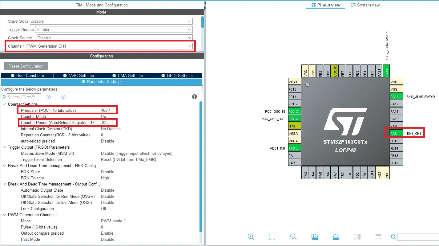
Configure the Timer to generate a 50 Hz PWM signal. By varying the duty cycle between 5% (1 ms pulse) and 10% (2 ms pulse), the ESC interprets the command as minimum to maximum throttle. This is the same principle used for driving servo motors.
The image below shows the prescaler and ARR values used to achieve the correct PWM frequency.
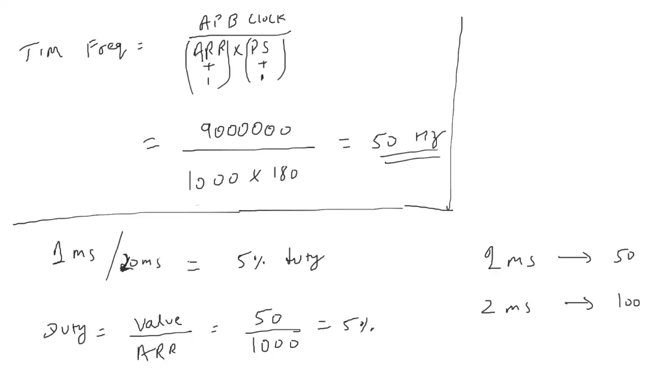
With ARR = 1000 and prescaler = 180, we achieve the required 50 Hz frequency. At runtime, we can update the capture/compare register (CCR1) dynamically to set duty cycles between 5% and 10%, directly controlling the BLDC motor speed via the ESC.
STM32 BLDC Motor Control Code Walkthrough
After configuring everything in CubeMX, let’s walk through the generated code and the key functions added to make the BLDC motor run with STM32. The code uses HAL drivers, DMA for ADC, and TIM1 PWM output.
Starting ADC with DMA
HAL_ADC_Start_DMA(&hadc1, (uint32_t *)&ADC_Data, 1);This line starts the ADC in DMA mode. The ADC continuously samples the potentiometer input at PA0 and stores results in the array ADC_Data. DMA takes care of moving data without CPU intervention, which improves efficiency and prevents blocking the main loop.
Starting the PWM
HAL_TIM_PWM_Start(&htim1, TIM_CHANNEL_1);This function enables the PWM output on TIM1 Channel 1 (pin PA8). Once enabled, the timer continuously generates PWM pulses at 50 Hz. These pulses act as throttle commands to the ESC, which drives the BLDC motor.
Using ADC Callback to Update PWM Duty Cycle
The ADC is running in DMA mode, which continuously stores the conversion result into the ADC_Data variable without CPU intervention. Once a conversion is complete, the DMA will trigger a callback function automatically.
uint16_t ADC_Data=0;
int ADC_Converted = 0;

long map(long x, long in_min, long in_max, long out_min, long out_max)
{
  return (x - in_min) * (out_max - out_min + 1) / (in_max - in_min + 1) + out_min;
}

void HAL_ADC_ConvCpltCallback(ADC_HandleTypeDef* hadc)
{
    ADC_Converted = map(ADC_Data, 0, 4095, 50, 100);
    TIM1->CCR1 = ADC_Converted;
}Inside this callback HAL_ADC_ConvCpltCallback() function, the raw ADC value (0–4095 for 12-bit resolution) is passed through a custom map() function. This maps it into the PWM duty cycle range (50–100), which corresponds to the ESC throttle range.
Finally, the mapped value is written directly into TIM1->CCR1. This will update the PWM duty cycle in real time, so the BLDC motor speed changes smoothly as the potentiometer rotates. Using a callback keeps the main loop free and ensures the motor control is always responsive.
Calibrating the ESC
Some ESCs (Electronic Speed Controllers) require calibration to understand the maximum and minimum PWM pulse widths. The code below calibrates the ESC according to the PWM cycle.
#if Calibrate
  TIM1->CCR1 = 100;  // Set the maximum pulse (2ms)
  HAL_Delay (2000);  // wait for 1 beep
  TIM1->CCR1 = 50;   // Set the minimum Pulse (1ms)
  HAL_Delay (1000);  // wait for 2 beeps
  TIM1->CCR1 = 0;    // reset to 0, so it can be controlled via ADC
#endifHere the code first sends a maximum pulse (2ms) and waits for the ESC to beep. Then, it sends the minimum pulse (1ms) and waits again. After you complete both steps, the ESC learns the valid PWM range and becomes ready for control through the potentiometer input.
- Send maximum pulse (2ms) → ESC beeps once
- Send minimum pulse (1ms) → ESC beeps again
- Calibration complete → ESC ready to use
You can easily enable or disable ESC calibration by changing the #define Calibrate macro. If set to 1, calibration runs during startup. If set to 0, the ESC will directly use ADC values for PWM control.
/* USER CODE BEGIN PTD */
#define Calibrate 1
/* USER CODE END PTD */Complete main() Function
Below is the complete main() function for this project. You can copy it into your STM32CubeIDE project after generating initialization code from CubeMX.
#define Calibrate 1
int main(void)
{
....
HAL_TIM_PWM_Start(&htim1, TIM_CHANNEL_1);
#if Calibrate
  TIM1->CCR1 = 100;  // Set the maximum pulse (2ms)
  HAL_Delay (2000);  // wait for 1 beep
  TIM1->CCR1 = 50;   // Set the minimum Pulse (1ms)
  HAL_Delay (1000);  // wait for 2 beeps
  TIM1->CCR1 = 0;    // reset to 0, so it can be controlled via ADC
#endif
HAL_ADC_Start_DMA(&hadc1, (uint32_t *)&ADC_Data, 1);
while (1)
{
}
}After the basic clock and peripheral initialization, start the TIM1 PWM on PA8. If Calibrate macro is set, thee function will start calibrating the ESC. Then, the ADC will start in the DMA mode. When the ADC conversion is finished, the HAL_ADC_ConvCpltCallback will be called and the calculated pulse value will be set to the motor.
The ADC will start the next conversion and this loop will keep running forever.
STM32 BLDC Motor Control Results
After you wire everything and flash the code, the STM32 sends PWM commands to the ESC, and the BLDC motor responds to the potentiometer input. At low potentiometer values, the motor starts slowly, and as you increase the input, the motor speed rises smoothly.
The video below shows the BLDC motor spinning under control of the STM32 PWM output.
As you turn the potentiometer knob, the motor speed gradually changes. This confirms that the ADC with DMA works correctly and directly updates the duty cycle into throttle commands for the ESC. The control is responsive and stable without jitter.
Troubleshooting Tips
- Motor not starting? Ensure the ESC is calibrated and powered by the LiPo battery. Some ESCs require an arming sequence (keeping throttle low for a few seconds).
- Jerky movement? Check the ground connections between STM32, ESC, and battery. A missing ground reference causes unstable PWM signals.
- No response from potentiometer? Verify that ADC channel 0 is enabled in CubeMX and DMA is linked to ADC1. Also confirm PA0 wiring.
- PWM not visible? Use a logic analyzer or oscilloscope to confirm TIM1 CH1 is generating pulses at 50 Hz.
- Overheating ESC or motor? Use a suitable BLDC motor and ESC rating for your LiPo battery. Avoid overloading the ESC with too high throttle on small motors.
Conclusion
In this tutorial, we successfully interfaced a BLDC motor with STM32 using an ESC and PWM output from TIM1. We learned how to configure the clock, ADC with DMA for potentiometer input, and generate PWM signals to control motor speed. This project shows how easily you can control real hardware once CubeMX is set up correctly. With these concepts, you can expand into advanced motor control applications like drones, robotics, and automation systems.
PROJECT DOWNLOAD
STM32 BLDC Motor Control FAQs


Hi! If I have a three phase motor do I need to have 3 different timers?