Updated On: May 6, 2026
STM32 FreeRTOS Software Timers Tutorial: Periodic, One-Shot & Button-Triggered
In the previous part of this series, we covered event flags and how to use them to synchronize tasks and handle hardware interrupts cleanly. In this part, we will look at software timers.
A software timer lets you run a function after a set period of time, without blocking a task or burning CPU cycles in a delay loop. You can use it to blink an LED, poll a sensor at a fixed interval, trigger a timeout, or debounce a button.
In this tutorial, we will cover how software timers work in FreeRTOS, what the CMSIS-RTOS V2 API looks like, and we will build examples using both periodic and one-shot timers on an STM32 board.
This is the Part 7 of the STM32 CMSIS-RTOS FreeRTOS series. You can go through the other parts of this series, here are the links:
- Part 1 — Configure CMSIS RTOS in STM32
- Part 2 — Creating Multiple Tasks and Priorities in CMSIS RTOS
- Part 3 — How to use Queues for inter-task communication
- Part 4 — Using Semaphores in CMSIS RTOS
- Part 5 — Using Mutexes in CMSIS RTOS
- Part 6 — Task Synchronization using Event Flags
- Part 8 — FreeRTOS Stack Management
Software Timers vs Hardware Timers on STM32
Let’s first understand what a software timer is and how it works inside FreeRTOS. This section covers the basics — why we use software timers, how FreeRTOS runs them internally, and the difference between the two timer types.
Why Use Software Timers Instead of Hardware Timers
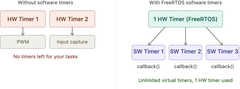
In embedded systems, hardware timers are a limited resource. A microcontroller typically has only a handful of them, and they are often already occupied by peripherals like PWM, input capture, or ADC triggering.
A software timer solves this by sitting on top of a single hardware timer managed by FreeRTOS. You can create as many software timers as the heap allows, and each one calls a callback function when its period expires.
The image below shows how multiple software timers share a single hardware timer resource.
How the Timer Daemon Task Works
FreeRTOS does not run timer callbacks inside the task or inside an interrupt. Instead, it has a dedicated background task called the timer daemon task (also known as the timer service task).
When a timer expires, FreeRTOS sends a message to the daemon task through an internal queue. The daemon task picks up that message and calls the callback function.
The image below shows how the timer daemon task fits into the FreeRTOS system.
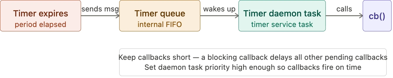
Two things to always keep in mind:
- Keep callbacks short and non-blocking. If you put a long delay inside a callback, the daemon task is blocked and all other waiting callbacks are delayed.
- Set the daemon task priority correctly. If the daemon task has a lower priority than your other tasks, callbacks will not fire on time. You can configure this in CubeMX under FreeRTOS advanced settings.
Periodic Timer vs One-Shot Timer
There are two types of software timers in FreeRTOS.
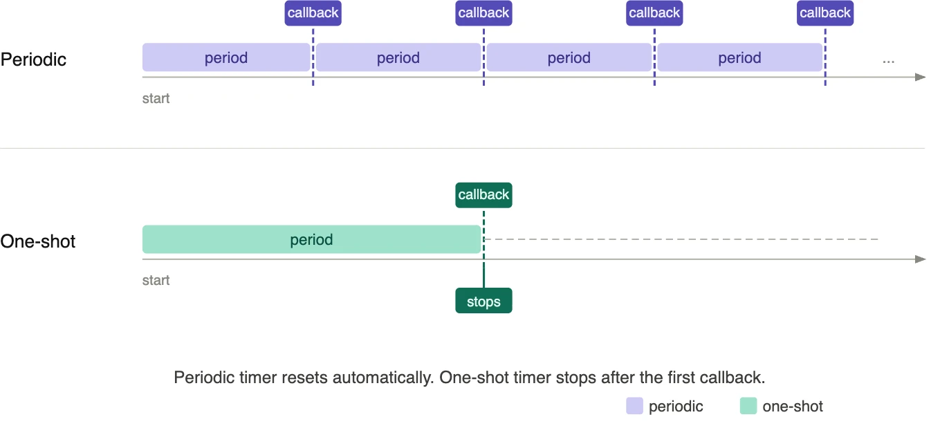
- A periodic timer keeps repeating. When the period expires, the callback runs, the timer resets, and it starts counting again. This continues until you explicitly stop it.
- A one-shot timer fires only once. After the period expires and the callback runs, the timer stops on its own. To run it again, you must restart it manually.
The image below shows the difference in behavior between the two timer types.
CMSIS-OS Timer API — Complete Reference
FreeRTOS provides a set of functions to create and manage software timers. In STM32CubeIDE with CMSIS-RTOS V2, these functions use the osTimer prefix. We will use four of them in this tutorial. Let us go through each one.
osTimerNew: Creating a Software Timer
This function creates a new software timer and returns a handle that we use in every subsequent call.
osTimerId_t osTimerNew(osTimerFunc_t func, osTimerType_t type, void *argument, const osTimerAttr_t *attr);The parameters are as follows:
func— the callback function to call when the timer expires.type— eitherosTimerPeriodicfor a repeating timer, orosTimerOncefor a one-shot timer.argument— a pointer passed to the callback. Set toNULLif we do not need it.attr— timer attributes such as name and memory allocation settings. CubeMX generates this for us.
When we create a timer through the CubeMX GUI, this function is called automatically inside main() function. You will see something like this in the generated code:
PeriodicTimerHandle = osTimerNew(PTCallback, osTimerPeriodic, NULL, &PeriodicTimer_attributes);
OneShotTimerHandle = osTimerNew(OSTCallback, osTimerOnce, NULL, &OneShotTimer_attributes);We do not need to call this manually. CubeMX handles it.
osTimerStart: Starting a Timer
Creating a timer does not start it automatically. We need to start it explicitly using:
osStatus_t osTimerStart(osTimerId_t timer_id, uint32_t ticks);timer_id— the handle returned byosTimerNew.ticks— the time period in milliseconds.
For example, to start the periodic timer with a one-second interval:
osTimerStart(PeriodicTimerHandle, 1000);And to start the one-shot timer with a five-second delay:
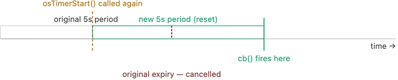
osTimerStart(OneShotTimerHandle, 5000);One important thing to note — if you call osTimerStart on a timer that is already running, it does not create a second timer. It simply resets the existing one and restarts the countdown from the new value. We will use this behavior intentionally when we demonstrate the one-shot timer reset later.
The image below shows what happens when osTimerStart is called on an already-running timer.
osTimerStop: Stopping a Timer
To stop a running timer before it expires, we use:
osStatus_t osTimerStop(osTimerId_t timer_id);Calling this on a periodic timer stops it from repeating. Calling it on a one-shot timer cancels it before it fires. In both cases, the callback is not called.
For example, to stop the periodic timer:
osTimerStop(PeriodicTimerHandle);The function returns an osStatus_t value. It returns osOK if the timer was stopped successfully. If you call it on a timer that is not running, it returns osErrorResource. You can check this return value if your application needs error handling, but in most cases we can ignore it.
osTimerIsRunning: Checking Timer State
Before starting or stopping a timer, it is useful to check whether it is currently active. We do this with:
uint32_t osTimerIsRunning(osTimerId_t timer_id);This function returns 1 if the timer is running, and 0 if it is stopped.
We will use this to conditionally start or stop timers. For example:
if (osTimerIsRunning(PeriodicTimerHandle))
{
osTimerStop(PeriodicTimerHandle);
}And to restart it only if it is currently stopped:
if (!osTimerIsRunning(periodic_timerHandle))
{
osTimerStart(PeriodicTimerHandle, 1000);
}STM32 FreeRTOS Timer CubeMX Setup
Let us set up the project in CubeMX. We will configure the timers, UART, and GPIO for this project.
Creating the Timers in CubeMX
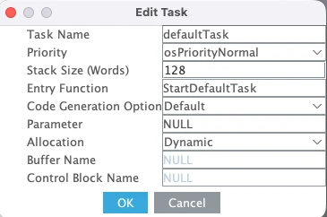
Go to the Tasks and Queues tab. A default task is already created here with normal priority and a stack size of 128 words. We will use this task in our project, so leave it as it is.
The image below shows the default task configuration.
Now go to the Timers and Semaphores tab. You will see a dedicated section for software timers. Click Add to create the first timer.
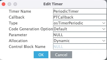
Set the following for the first timer:
- Type — Periodic
- Timer Name —
PeriodicTimer - Callback —
PTCallback - Allocation — Dynamic
The image below shows the first timer configured as a periodic timer.
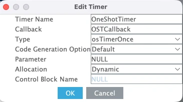
Click Add again to create the second timer. Set the following:
- Type — Timer Once
- Timer Name —
OneShotTimer - Callback —
OSTCallback - Allocation — Dynamic
The image below shows the second timer configured as a one-shot timer.
The table below summarizes the timer configuration:
| Parameter | Periodic Timer | One-Shot Timer |
|---|---|---|
| Type | Periodic | One Shot |
| Name | PeriodicTimer | OneShotTimer |
| Callback | PTCallback | OSTCallback |
| Allocation | Dynamic | Dynamic |
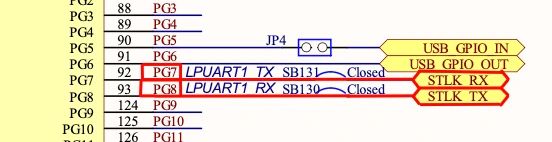
Configuring LPUART1 for printf Output
We will use printf to print the received data to a serial console. On the STM32L496 Nucleo board, the Virtual COM port routes UART data through the ST-LINK USB connection. Looking at the board schematic, ST-LINK RX is connected to LPUART1 TX and ST-LINK TX is connected to LPUART1 RX. These map to pins PG7 and PG8.
Go to Connectivity and enable LPUART1 in Asynchronous mode. By default, CubeMX assigns pins PC0 and PC1, so change these to PG7 (TX) and PG8 (RX).
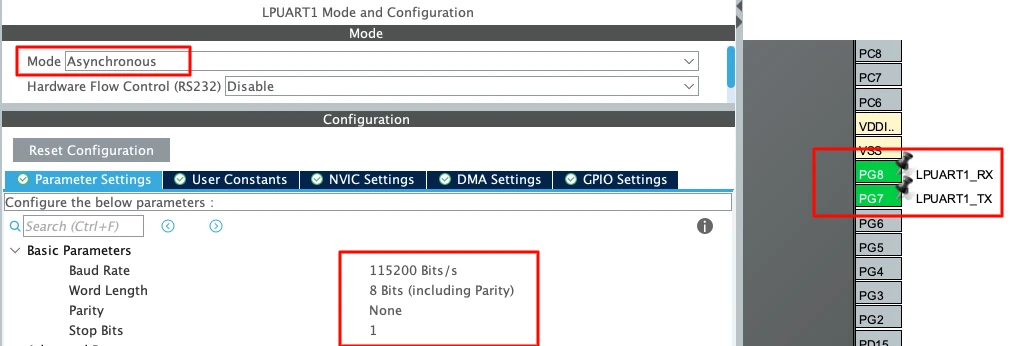
Use the following settings:
| Parameter | Value |
|---|---|
| Baud Rate | 115200 |
| Word Length | 8 bits |
| Parity | None |
| Stop Bits | 1 |
This is the standard UART configuration and matches what we will set in the serial console later.
Configuring GPIO for LED and button
Now we will configure the onboard LED. According to the board schematic, the LEDs on Nucleo-L496 are connected as shown below:
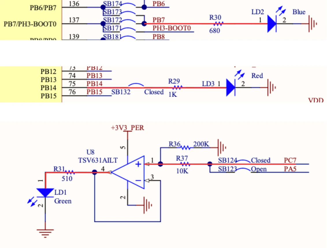
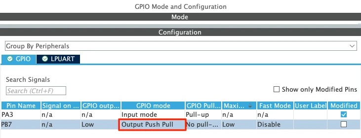
I am just going to use the Blue LED for this tutorial, which is connected to pin PB7. Therefore, configure the pins PB7 in the output mode. This is shown in the image below.
We also need a button. I have connected the button between pin PA3 and Ground. The pin will be high by default, and when the button is pressed, it will be pulled low to the ground.
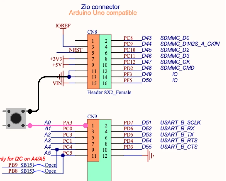
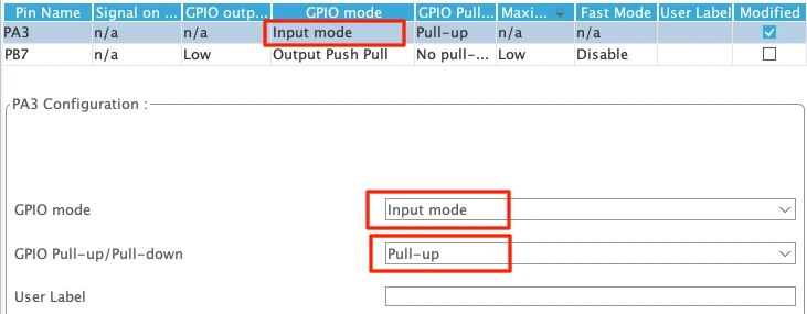
Configure the pin PA3 in the GPIO Input Mode. Set the pull to Pull-up so the pin stays high by default and goes low when the button is pressed.
Changing HAL Time Base from SysTick to TIM6
This step is very important in STM32 FreeRTOS projects. By default, STM32 uses SysTick as the HAL time base. But FreeRTOS also uses SysTick for its scheduler.
If both HAL and FreeRTOS share SysTick, it may create timing conflicts.
So we should dedicate:
- SysTick → FreeRTOS Scheduler
- TIM6 (or TIM7) → HAL Time Base
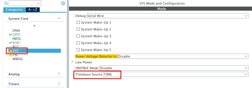
- Go to System Core → SYS
- Change Timebase Source from SysTick to TIM6 (or TIM7)
TIM6 and TIM7 are basic timers. They do not support PWM or advanced features. That is why they are ideal for this purpose.
Enabling Newlib Reentrant Support
Go to Middleware → FreeRTOS → Advanced Settings and Enable Use newlib reentrant.
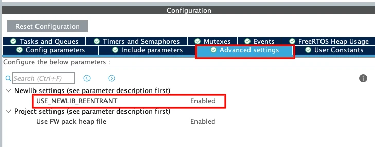
In an RTOS environment, multiple tasks may call functions like printf(); sprintf(); malloc(); etc. These standard C library functions are not thread-safe by default.
If two tasks call printf() at the same time, the output may get corrupted. Enabling newlib reentrant makes these functions safe in multitasking systems. It uses slightly more memory, but it prevents difficult debugging issues later.
STM32 FreeRTOS Timer Code: Periodic & One-Shot
CubeMX has already generated the initialization code for both timers inside main()function:
PeriodicTimerHandle = osTimerNew(PTCallback, osTimerPeriodic, NULL, &PeriodicTimer_attributes);
OneShotTimerHandle = osTimerNew(OSTCallback, osTimerOnce, NULL, &OneShotTimer_attributes);Both timers are created but not started. We need to start them manually from within our code. Let us go through each part.
Starting the Periodic Timer and Writing Its Callback
We start the periodic timer at the beginning of StartDefaultTask, before the infinite loop. Since this line runs only once, it is the right place to start a timer that is meant to run continuously.
void StartDefaultTask(void *argument)
{
    osTimerStart(PeriodicTimerHandle, 1000);

    for(;;)
    {
        // ...
        osDelay(1);
    }
}We pass 1000 as the period, so the callback fires every one second.
Now let us write the callback. The periodic timer callback PTCallback simply prints a log message to the serial console to confirm it is running.
void PTCallback(void *argument)
{
    printf("Data Sent from Periodic Timer's Callback\n");
}Keep in mind that this callback runs inside the timer daemon task. Keep it short. Do not add any blocking calls or long delays here.
Starting the One-Shot Timer on Button Press
Inside the infinite loop, we poll pin PA3. If it reads GPIO_PIN_RESET, the button has been pressed and the pin has been pulled LOW. At that point, we turn the LED on and start the one-shot timer with a 5000ms delay.
for(;;)
{
if (HAL_GPIO_ReadPin(GPIOA, GPIO_PIN_3) == GPIO_PIN_RESET)
{
HAL_GPIO_WritePin(GPIOB, GPIO_PIN_7, GPIO_PIN_SET);
osTimerStart(OneShotTimerHandle, 5000);
}
osDelay(1);
}Five seconds after the button is pressed, the one-shot timer expires and OSTCallback is called. Inside this callback, we turn the LED off and print a log message to confirm the timer has fired.
void OSTCallback(void *argument)
{
HAL_GPIO_WritePin(GPIOB, GPIO_PIN_7, GPIO_PIN_RESET);
printf("##### TIMER EXPIRED #####\n\n");
}Notice the behavior when the button is pressed multiple times before the five seconds are up. Every call to osTimerStart on an already-running one-shot timer resets it and pushes the expiry forward by another 5000ms. The timer never fires as long as you keep pressing within the window. This is useful for implementing inactivity detection or debounce logic.
We also handle the periodic timer inside the default task and the one-shot callback. When the button is pressed, we check if the periodic timer is running and stop it. When the one-shot timer expires, we check if the periodic timer is stopped and restart it.
/* In the default task — stop periodic timer on button press */
if (osTimerIsRunning(PeriodicTimerHandle) == 1)
{
osTimerStop(PeriodicTimerHandle);
}
/* In OSTCallback — restart periodic timer after one-shot expires */
if (osTimerIsRunning(PeriodicTimerHandle) == 0)
{
osTimerStart(PeriodicTimerHandle, 1000);
}We will cover this behavior in detail in the next section. For now, let us look at the complete code.
Complete Code
Here is the full code combining everything we have written so far.
/* USER CODE BEGIN Includes */
#include "stdio.h"
/* USER CODE END Includes */
/* USER CODE BEGIN 0 */
int __io_putchar(int ch)
{
uint8_t c = ch;
HAL_UART_Transmit(&hlpuart1, &c, 1, HAL_MAX_DELAY);
return ch;
}
/* USER CODE END 0 */
void StartDefaultTask(void *argument)
{
/* Start the periodic timer — fires every 1 second */
osTimerStart(PeriodicTimerHandle, 1000);
for(;;)
{
/* Check for button press — PA3 reads LOW when pressed */
if (HAL_GPIO_ReadPin(GPIOA, GPIO_PIN_3) == GPIO_PIN_RESET)
{
/* Turn LED on */
HAL_GPIO_WritePin(GPIOB, GPIO_PIN_7, GPIO_PIN_SET);
/* Start one-shot timer — fires once after 5 seconds */
osTimerStart(OneShotTimerHandle, 5000);
/* Stop the periodic timer while one-shot is running */
if (osTimerIsRunning(PeriodicTimerHandle) == 1)
{
osTimerStop(PeriodicTimerHandle);
}
}
osDelay(1);
}
}
/* Periodic timer callback — called every 1 second */
void PTCallback(void *argument)
{
    printf("Data Sent from Periodic Timer's Callback\n");
}
/* One-shot timer callback — called once after 5 seconds */
void OSTCallback(void *argument)
{
/* Turn LED off */
HAL_GPIO_WritePin(GPIOB, GPIO_PIN_7, GPIO_PIN_RESET);
printf("##### TIMER EXPIRED #####\n\n");
/* Restart the periodic timer if it was stopped */
if (osTimerIsRunning(PeriodicTimerHandle) == 0)
{
osTimerStart(PeriodicTimerHandle, 1000);
}
}A few things to note about this code:
- The
__io_putcharfunction redirectsprintfoutput through LPUART1 to the serial console. Make surestdio.his included at the top. osDelay(1)inside the task loop gives the scheduler a chance to run other tasks and also acts as a basic debounce for the button.- Both
osTimerIsRunningchecks use the return value to avoid redundant start or stop calls on a timer that is already in the desired state.
Output
The GIF below shows the complete behavior of both timers running on the STM32 Nucleo board.

The periodic timer prints a log message every second. Pressing the button turns the LED on and starts the one-shot timer. After five seconds, the LED turns off and the TIMER EXPIRED message appears on the console. Pressing the button again before the five seconds are up resets the one-shot timer, keeping the LED on and pushing the expiry forward.
Stop & Restart STM32 FreeRTOS Timer Dynamically
So far we have seen how to start both timers. But FreeRTOS also lets us stop a running timer and restart it later from a different point in the code. In this section, we will use osTimerStop and osTimerIsRunning to stop the periodic timer when the button is pressed, and restart it automatically once the one-shot timer expires.
Stopping the Periodic Timer on Button Press
Inside the default task, we already start the one-shot timer and turn the LED on when the button is pressed. We now add one more step — we check if the periodic timer is currently running and stop it.
if (HAL_GPIO_ReadPin(GPIOA, GPIO_PIN_3) == GPIO_PIN_RESET)
{
    HAL_GPIO_WritePin(GPIOB, GPIO_PIN_7, GPIO_PIN_SET);
    osTimerStart(OneShotTimerHandle, 5000);

    if (osTimerIsRunning(PeriodicTimerHandle) == 1)
    {
        osTimerStop(PeriodicTimerHandle);
    }
}We use osTimerIsRunning before calling osTimerStop. This avoids calling stop on a timer that is already stopped — for example, if the button is pressed a second time while the one-shot timer is still counting. In that case, the periodic timer is already stopped, so we skip the stop call entirely.
Restarting the Periodic Timer from the One-Shot Callback
Once the one-shot timer expires, OSTCallback is called. Inside this callback, we turn the LED off and then check if the periodic timer is stopped. If it is, we restart it.
void OSTCallback(void *argument)
{
    HAL_GPIO_WritePin(GPIOB, GPIO_PIN_7, GPIO_PIN_RESET);
    printf("##### TIMER EXPIRED #####\n\n");

    if (osTimerIsRunning(PeriodicTimerHandle) == 0)
    {
        osTimerStart(PeriodicTimerHandle, 1000);
    }
}Again, we use osTimerIsRunning before restarting. This ensures we do not accidentally restart a timer that is already running — for example, if somehow the periodic timer was never stopped before this callback fired.
Complete Code
Here is the full code for this section with both the stop and restart logic included.
void StartDefaultTask(void *argument)
{
    /* Start the periodic timer — fires every 1 second */
    osTimerStart(PeriodicTimerHandle, 1000);

    for(;;)
    {
        if (HAL_GPIO_ReadPin(GPIOA, GPIO_PIN_3) == GPIO_PIN_RESET)
        {
            /* Turn LED on */
            HAL_GPIO_WritePin(GPIOB, GPIO_PIN_7, GPIO_PIN_SET);

            /* Start one-shot timer — fires once after 5 seconds */
            osTimerStart(OneShotTimerHandle, 5000);

            /* Stop the periodic timer if it is currently running */
            if (osTimerIsRunning(PeriodicTimerHandle) == 1)
            {
                osTimerStop(PeriodicTimerHandle);
            }
        }
        osDelay(1);
    }
}

/* Periodic timer callback — called every 1 second */
void PTCallback(void *argument)
{
    printf("Data Sent from Periodic Timer's Callback\n");
}

/* One-shot timer callback — called once after 5 seconds */
void OSTCallback(void *argument)
{
    /* Turn LED off */
    HAL_GPIO_WritePin(GPIOB, GPIO_PIN_7, GPIO_PIN_RESET);

    printf("##### TIMER EXPIRED #####\n\n");

    /* Restart the periodic timer if it is currently stopped */
    if (osTimerIsRunning(PeriodicTimerHandle) == 0)
    {
        osTimerStart(PeriodicTimerHandle, 1000);
    }
}Output
The GIF below shows the full dynamic behavior on the STM32 Nucleo board. The periodic timer runs and prints a log every second. When the button is pressed, the periodic timer stops and the LED turns on. After five seconds, the one-shot timer expires, the LED turns off, and the periodic timer restarts automatically.

STM32 FreeRTOS Software Timers Tutorial — Video Walkthrough
This video covers the complete FreeRTOS software timer workflow on STM32: osTimerNew, osTimerStart, osTimerStop, and osTimerIsRunning API reference, CubeMX setup for periodic and one-shot timers, LPUART1 printf output, PB7 LED and PA3 button GPIO configuration, and a live combined demo — periodic timer logging every second, pausing on button press, one-shot timer turning the LED off after 5 seconds, and periodic timer restarting automatically — all on the STM32 Nucleo-L496ZG-P.
STM32 FreeRTOS Timers — Frequently Asked Questions
Conclusion
FreeRTOS software timers are one of the cleanest tools in the RTOS toolkit. No register configuration, no interrupt vectors, no peripheral clock enable — just a callback function, a period in milliseconds, and a type. The timer daemon task handles everything else in the background.
In this tutorial you built two timers on the STM32 Nucleo-L496ZG-P: a periodic timer that fires its callback every second and logs to the serial console indefinitely, and a one-shot timer that turns an LED on when the button is pressed and off exactly five seconds later. You saw how osTimerStart() resets a running timer rather than stacking a second one — behaviour you can use directly for inactivity detection, debounce logic, or any watchdog-style pattern that restarts on activity. And you saw how to coordinate both timers: the periodic timer pauses the moment the button is pressed and resumes the moment the one-shot expires, with osTimerIsRunning() as the state check in both directions.
The callback rules from this tutorial carry forward into every subsequent FreeRTOS design: keep callbacks short, never block, never call osDelay() or any API that yields. The timer daemon task is a shared resource — a callback that blocks delays every other timer in the system. If you need heavier processing on a timer event, set an event flag from the callback and handle the work in a dedicated task. The Event Flags tutorial covers exactly this pattern.
The next part in this series is Part 8 — Stack Management, Monitoring & Overflow Detection, where you will instrument a running FreeRTOS application with uxTaskGetStackHighWaterMark(), enable the stack overflow hook, and learn to size task stacks correctly before deploying to production. Browse the full STM32 FreeRTOS series for all parts.
Download STM32 FreeRTOS Software Timers Project Files
Complete STM32CubeIDE project for the STM32 Nucleo-L496ZG-P with two CMSIS-OS V2 software timers: PeriodicTimer (1-second PTCallback with printf logging) and OneShotTimer (5-second OSTCallback that turns off the PB7 LED). Includes button-triggered start on PA3, osTimerIsRunning() stop/restart logic, LPUART1 printf at 115200 baud, HAL time base on TIM6, and newlib reentrant enabled. Free to download — support the work if it helped you.
Browse More STM32 FreeRTOS Tutorials
STM32 FreeRTOS Multiple Tasks, Priorities & Preemption — CMSIS-RTOS V2 Guide
STM32 FreeRTOS Queue Tutorial: Inter-Task Communication with CMSIS-OS V2
STM32 FreeRTOS Semaphores: How to Use Binary and Counting Semaphores
STM32 FreeRTOS Mutex: Priority Inheritance & Recursive Mutex
STM32 FreeRTOS Event Flags: osFlagsWaitAll, WaitAny & ISR Callbacks

Subscribe
Login
0 Comments
Newest
