Data Logger using STM32 and ESP8266
I have covered a tutorial about Webserver using STM32 and ESP8266, where ESP8266 was used to create a webserver to control the LED on STM32. This tutorial will also cover another application of ESP8266, and here we will use it to log the data into the Thingspeak server.
This data will be collected from the ADC, potentiometer in my case, and some other local variables, and the values will be updated on the Thingspeak server.
************* UPDATE 2 ***************
L4 series and G series MCUs have some issues with UART_ISR_TXE. If you are having issues even after making changes according to UPDATE 1, then Replace the Uart_isr with the file https://controllerstech.com/wp-content/uploads/2020/08/Uart_Isr_single_new.c
************* UPDATE 1 ***************
Those, who have errors in the Uart_isr function, eg- F7 series MCU, replace the Uart_isr functon with the one provided in this file https://controllerstech.com/wp-content/uploads/2020/04/Uart_Isr_single.c
VIDEO TUTORIAL
You can check the video to see the complete explanation and working of this project.
SETUP
Setup part is very simple. All we need to do is enable the UART at 115200 baud rate. And also make sure to enable the interrupt, because the entire ring buffer concept works on interrupt itself
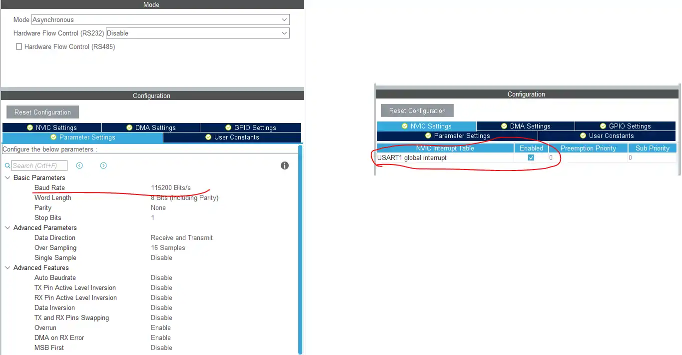
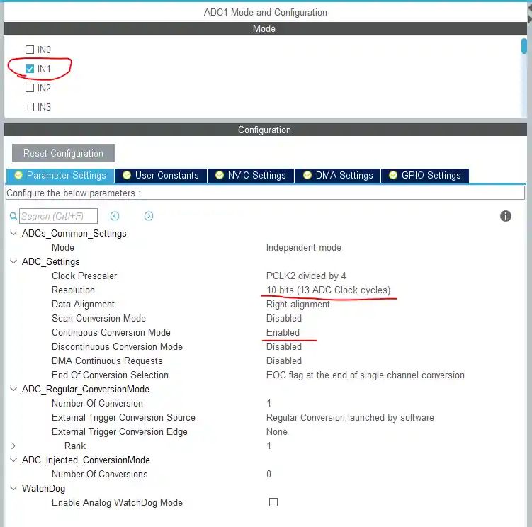
Also for the ADC, I am using only 1 channel, where the potentiometer is connected. For more details on ADC, and how to set it up and use it, check the link https://controllerstech.com/stm32-adc-multi-channels/
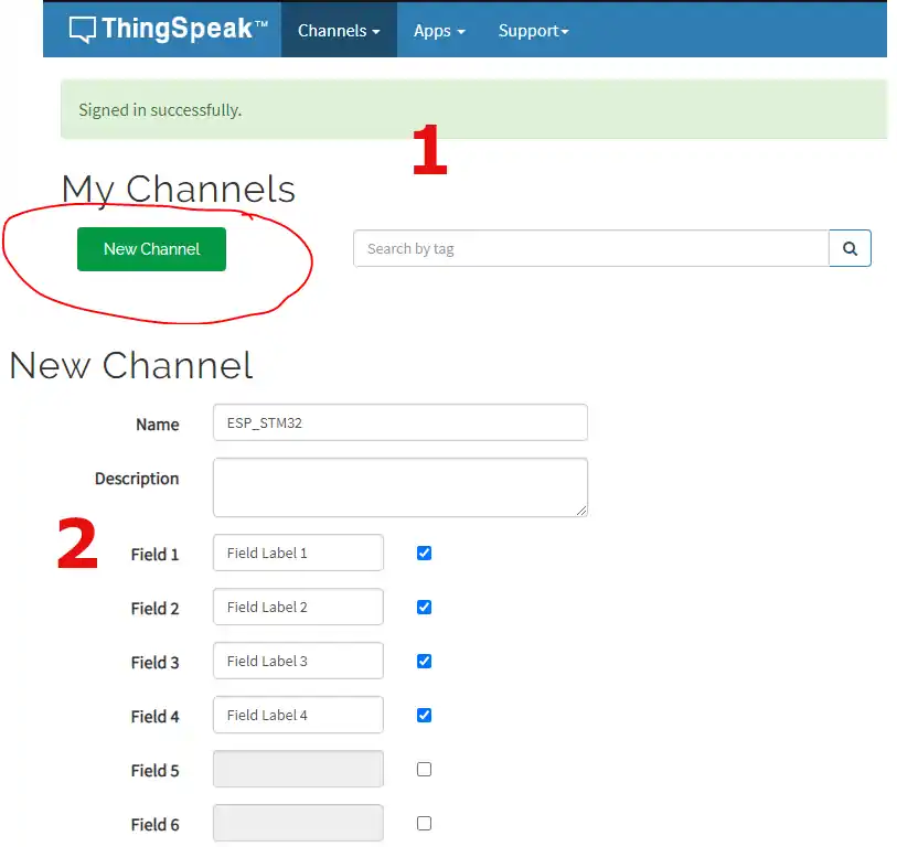
Next, we need to setup the Thingspeak for receiving data. Create an account on Thingspeak.com if you don’t have one.
Go to channels, and create NEW CHANNEL
You can setup the number of fields you want, as in the picture below I will send the 4 variables and that’s why selected 4 fields to store them
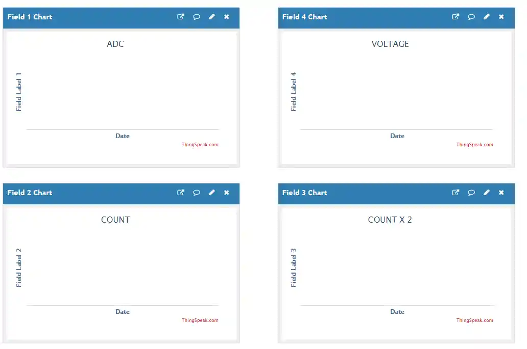
you can give name to these field charts, and arrange their positions. My final setup looks as shown below
Finally, we need to include the library files into the project. Just copy the ESPDataLogger.c and UartRingbuffer.c files into the src and ESPDataLogger.h and UartRingbuffer.h files into the inc directories of your project.
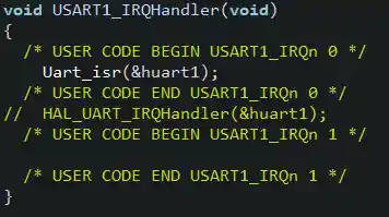
We need to modify the UART interrupt handler, and redirect it to our interrupt handler. Modify it as shown in the picture below
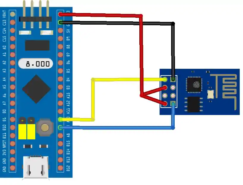
CONNECTION
The connection of ESP8266 with the STM32 will be same as always. Connect the TX to RX pin, and RX to TX pin as shown below
Some insight into the code
void ESP_Init (char *SSID, char *PASSWD)
{
	char data[80];

	Ringbuf_init();

	Uart_sendstring("AT+RST\r\n");
	HAL_Delay(1000);

	Uart_flush();

	/********* AT **********/
	Uart_sendstring("AT\r\n");
	while(!(Wait_for("OK\r\n")));

	Uart_flush();


	/********* AT+CWMODE=1 **********/
	Uart_sendstring("AT+CWMODE=1\r\n");
	while (!(Wait_for("OK\r\n")));

	Uart_flush();


	/********* AT+CWJAP="SSID","PASSWD" **********/
	sprintf (data, "AT+CWJAP=\"%s\",\"%s\"\r\n", SSID, PASSWD);
	Uart_sendstring(data);
	while (!(Wait_for("GOT IP\r\n")));

	Uart_flush();

	/********* AT+CIPMUX=0 **********/
	Uart_sendstring("AT+CIPMUX=0\r\n");
	while (!(Wait_for("OK\r\n")));

	Uart_flush();

}ESP_INIT will initialize the ESP8266 by connecting it with the provided Access Point
AT+CIPMUX = 0 is to disable the Multiple connections. This is necessary for setting up the TCP connection
void ESP_Send_Multi (char *APIkey, int numberoffileds, uint16_t value[])
{
	char local_buf[500] = {0};
	char local_buf2[30] = {0};
	char field_buf[200] = {0};


	Uart_sendstring("AT+CIPSTART=\"TCP\",\"184.106.153.149\",80\r\n");
	while (!(Wait_for("OK\r\n")));

	sprintf (local_buf, "GET /update?api_key=%s", APIkey);
	for (int i=0; i<numberoffileds; i++)
	{
		sprintf(field_buf, "&field%d=%u",i+1, value[i]);
		strcat (local_buf, field_buf);
	}

	strcat(local_buf, "\r\n");
	int len = strlen (local_buf);

	sprintf (local_buf2, "AT+CIPSEND=%d\r\n", len);
	Uart_sendstring(local_buf2);
	while (!(Wait_for(">")));

	Uart_sendstring (local_buf);
	while (!(Wait_for("SEND OK\r\n")));

	while (!(Wait_for("CLOSED")));

	bufclr(local_buf);
	bufclr(local_buf2);

	Ringbuf_init();

}ESP_Send_Multi is to send the data to the multiple fields
@APIKey is the unique key that you can get from the Thingspeak channel setting
@numberoffields are the number of fields in your channel, where you want to update the data
@value[] is the array of values that you want to send to the thingspeak channel
Updating multiple fields at once becomes a requirement because Thingspeak only allows to communicate once in every 15 seconds. So it’s better if we update all the fields at once.
float Voltage = 0;
uint16_t ADC_Value = 0;
uint8_t count = 0;

uint16_t Value_Buf [4];

uint16_t ADC_Get_Value (void)
{
	uint16_t val = 0;
	HAL_ADC_Start(&hadc1);
	HAL_ADC_PollForConversion(&hadc1, 100);
	val = HAL_ADC_GetValue(&hadc1);
	HAL_ADC_Stop(&hadc1);
	return val;
}

int main(void)
{

  HAL_Init();

  SystemClock_Config();

  MX_GPIO_Init();
  MX_ADC1_Init();
  MX_USART1_UART_Init();
  /* USER CODE BEGIN 2 */

  ESP_Init("myphone", "12345678");

  while (1)
  {

	  ADC_Value = ADC_Get_Value();
	  Voltage = ((float) ADC_Value * 5.0 / 1023);
	  count++;

	  Value_Buf[0] = ADC_Value;
	  Value_Buf[1] = count;
	  Value_Buf[2] = count*2;
	  Value_Buf[3] = Voltage;

	  ESP_Send_Multi("77C19M0JJMDFS5SA", 4, Value_Buf);

	  HAL_Delay(15000); // must be at least 15 sec delay between 2 send
  }
}As mentioned above, first of all I am polling for the ADC value
Then converting the value to the respective voltage
Then incrementing the count variable
Next, storing the values to the respective positions in the array, in the order that I want to send them
And finally, send the values using the ESP_Send_Multi function
Result

You can see above, the values are updating every 15 seconds. There is change in ADC value, as I was rotating the potentiometer, and also the voltage follow the same change. The count, and count X 2 increments every 15 seconds too.


Hello,
i have stm32l4 and with UPDATE 2 function getting error ‘USART_CR1_RXNEIE_RXFNEIE’ undeclared
without fix update i cant get any data on my th rx connection.
I couldnt find any solution for that.
I’m using STM32wle5ccu6 based board with esp32 c3 mini embedded. ESP_Init() function is not working in my case. I’m connecting the board with st link v2 debugger. The board has only SWD port. it doesn’t show on the COM port. It runs my code block with trying to initialize ESP32 c3 module in it. I don’t how enable the esp32 c3 mini in it.
where did you get “myphone” and “12345678” ?
This is the hotspot created on phone.
Hello,
When the wifi in the environment drops and comes back up, its stuck on IsDataAvailable() function.
Do you have any suggestions for solving this problem?
Thank you 🙂
Hello sir,
Can you provide me this code for keil ide
Hi, ı have a problem with uart_isr() function. I have also downloaded the function which you have noticed above of page but it still stand. I am using stm32f429ı discovery board. What is the problem ? please help me…
can I turn on a led from thingspeak??
thanks
thanks for your help
where do i download the code?
click the download button
hi. Im using f4 discovery. İ have ESP_init() problem. Inside of this one, its stuck on Wait_for() function, and inside of this one, its stuck on IsDataAvailable() function. I have same problem with Pepe.
you have to be more precise. Debug you code, and see what command it stucks in.
I have a problem with the code, it stuck on the ESP_init() function. Inside of this one, its stuck on Wait_for() function, and inside of this one, its stuck on IsDataAvailable() function.
did you find solution for this problem?
I have the same problem… what is the solution?
could be anything..
you can separately connect the esp8266 to PC using FTDI and test those commands
also separately check if ring buffer (rx_buffer) is able to receive data when you send from the computer
Debug your code.. find the problem..
The solution is change the crystal clock to ceramic resonator.
Hello,
first of all excuse my bad english, please.
The proposal changing the clock doesn’t work out by my problem with the Wait_for() function.
The code stucks always in the Wait_for() function.
My problem is that the program goes in line 226 (UartRingbuffer.c) every time in the if-function.
The reason for is that the Uart_peek() function (code line 161 UartRingbuffer.c) returns at every time _rx_buffer->buffer[_rx_buffer->tail];
it should be ADC_Value * 3.3 / 4096);