Home ▸ STM32 Tutorials ▸ STM32 CAN ▸
Updated On: September 29, 2025
STM32 FDCAN in Loopback Mode
This is another tutorial covering the CAN peripheral of STM32 and today we will go a little further with FDCAN. It stands for Flexible Data-Rate Controlled Area Network.
As the name suggests, this is a major upgrade over the regular CAN specifically in the areas where the CAN was very limited, for eg- the data size and the bandwidth. The FDCAN overcomes these disadvantages making it suitable for modern applications.
This tutorial will cover the configuration of the FDCAN along with a simple test performed using the Loopback mode. A more practical application using the 2 different FDCAN devices will be covered in the next tutorial.
Let’s start with understanding the FDCAN format and how is it different from the CAN
VIDEO TUTORIAL
You can check the video to see the complete explanation and working of this project.
FDCAN Format
Below is the image showing the format of the FDCAN
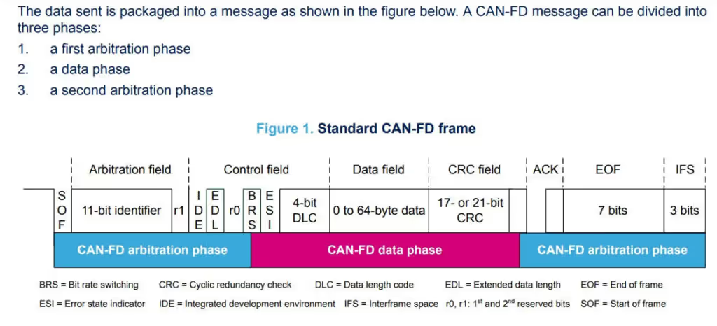
- The first arbitration phase is a message that contains:
- a start of frame (SOF)
- an ID number and other bits, that indicate the purpose of the message (supplying or requesting data), and the speed and format configuration (CAN or CAN-FD)
- The data transmission phase consists on:
- the data length code (DLC), that indicates how many data bytes the message contains
- the data the user wishes to send
- the check cyclic redundancy sequence (CRC)
- a dominant bit
- The second arbitration phase contains:
- the receiver of acknowledgment (ACK) transmitted by other nodes on the bus
- the end of frame (EOF)
No message is transmitted during the IFS: the objective is to separate the current frame with the next.
Let’s see the Frame architecture comparison between CAN-FD and CAN 2.0
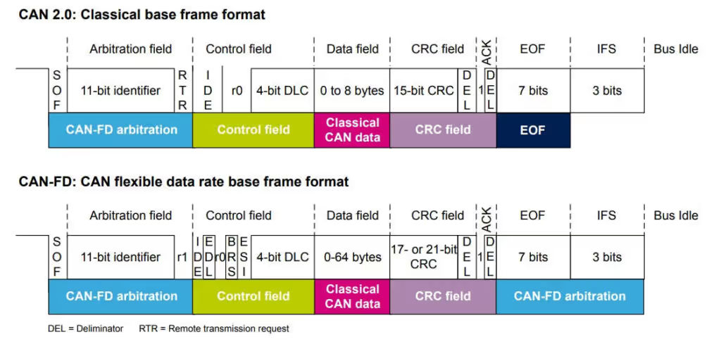
- CAN 2.0 sends an RTR bit to precise the type of frame: data frame (RTR is dominant) or remote frame (RTR is recessive), whereas the CAN-FD sends always a dominant RRS (reserved) as it only supports data frames
- In the CAN-FD frame, three new bits are added in the control field compared to CAN 2.0:
- Extend data length (EDL) bit: is recessive to signify the frame is CAN-FD, otherwise this bit is dominant (called R0) in CAN 2.0 frame.
- Bit rate switching (BRS): indicates whether two bit rates are enabled (for example when the data phase is transmitted at a different bit rate to the arbitration phase).
- Error state indicator (ESI): indicates if the node is in error-active or error-passive mode.
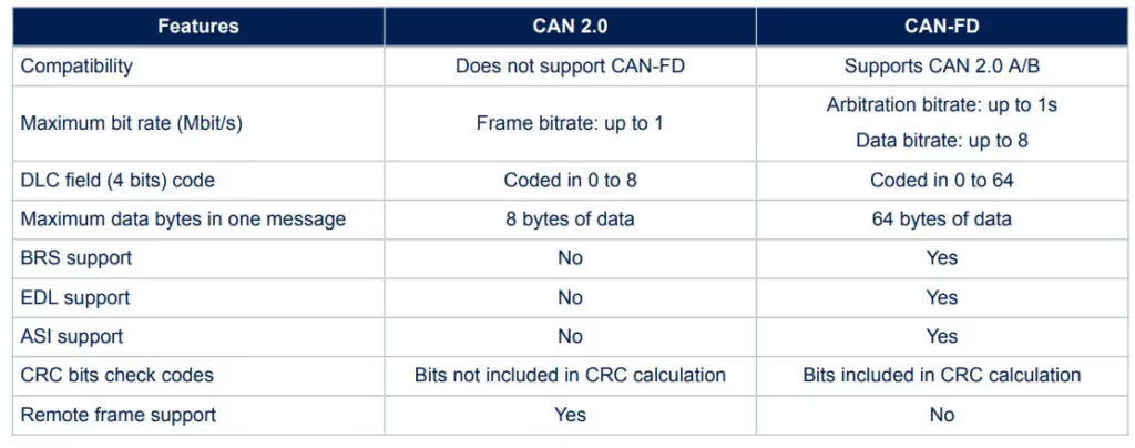
The Main differences between CAN-FD and CAN 2.0 are shown below:
The Setup
This section is going to be very large, as we will cover the cubeMX setup, along with a huge number of parameters and the reasons behind their values.
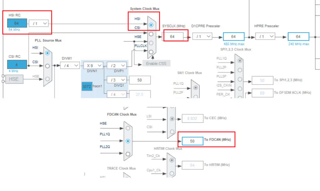
I am choosing the 64 Mhz internal clock in this tutorial. The reason for the same will be explained in a while. Also note that the FDCAN clock is 50 Mhz. This will be used in the later part of the tutorial.
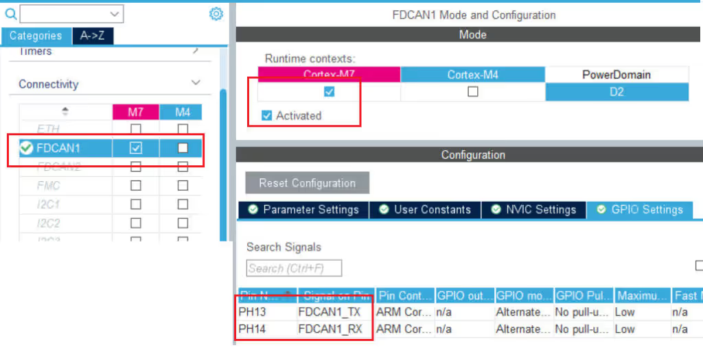
Here I have enabled the FDCAN for the cortex M7. Note the pins PH13 is the TX pin and PH14 is the RX pin.
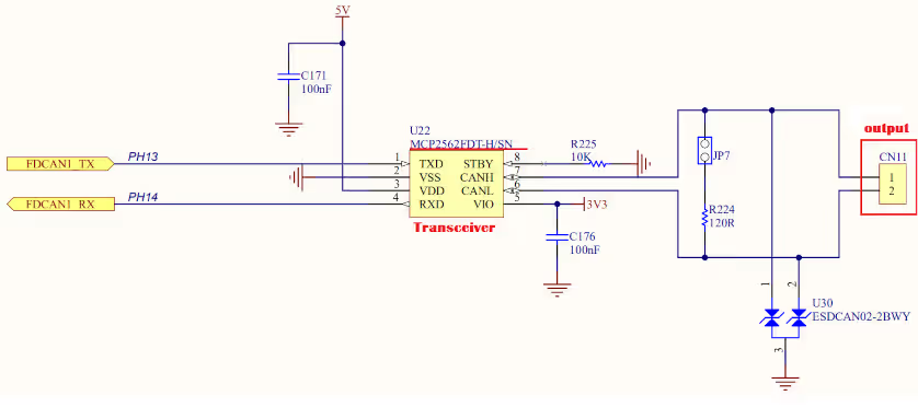
The controller I am using, H745 Discovery, has the Transceiver on the board itself. MCP2562FDT is connected to the pins PH13 and PH14. The connectors available on the board are for the CANH and CANL. This is shown on the picture below.
There are a lot of parameters to configure in the CAN-FD, so we will see few at a time
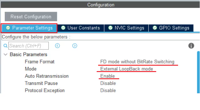
- Here I am using the format as FD Mode without bitrate switching.
- Actually the FD CAN can transfer arbitration field and data filed at different bitrates. But I want to use the same bitrate for both of them.
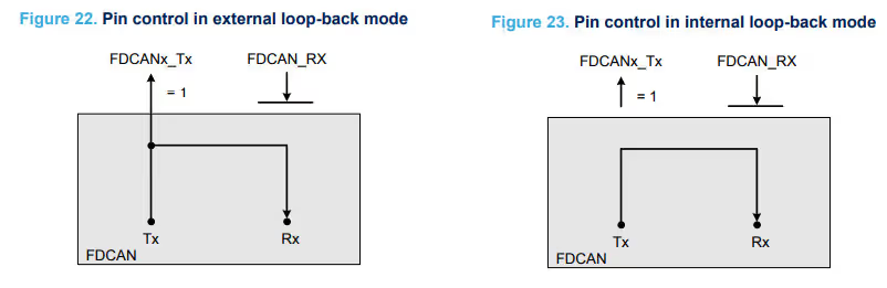
- The mode is set to External LoopBack Mode. You can also use the Internal LoopBack, as they are mostly the same.
- I have enabled the Auto Retransmission in case of errors, and disabled the other non important parameters.
In the LoopBack Mode, The FDCAN treats its own transmitted messages as received messages and stores them if they pass the acceptance filtering. Actually the TX Pin is internally connected to the RX pin as shown below.
To calculate these set of parameters we need to use an external calculator, which could be found at https://www.kvaser.com/support/calculators/can-fd-bit-timing-calculator/
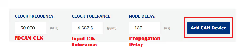
The first 3 parameters we need to input are the FDCAN CLK Frequency, The Input CLK Tolerance and the Transceiver node delay.
The FDCAN clock Frequency is 50 MHz and we have already covered this in the beginning of this section.
Next comes the Clock Tolerance. I mentioned in the beginning that I am using the internal clock in this tutorial, and it was because it’s easier to find the clock tolerance for the input clock. The picture below summarizes it:
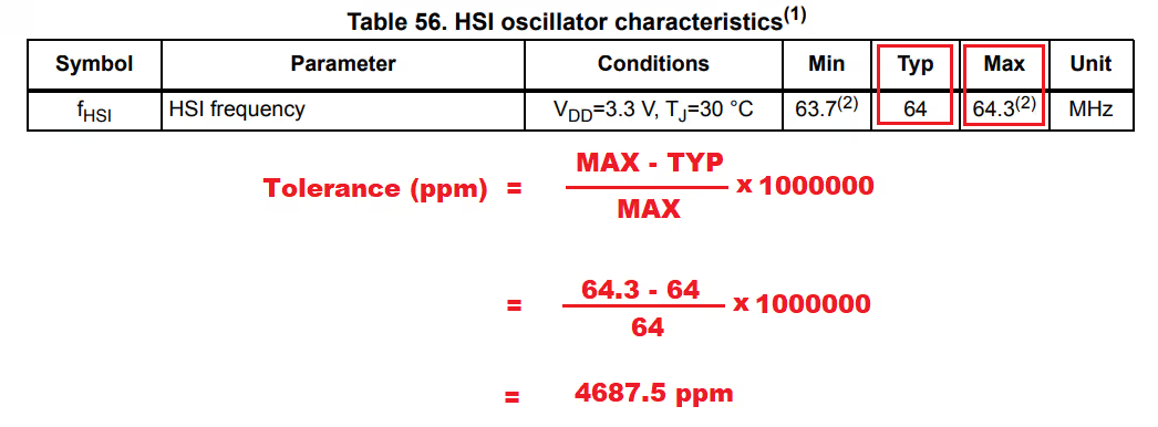
Finally we have the node delay or Propagation Delay. This can be found in the AC characteristics of the Transceiver you are using.
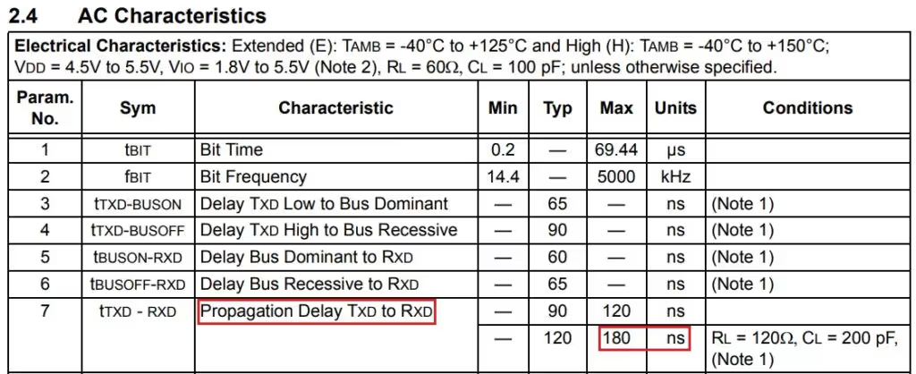
As I mentioned the board I am using have an on board transceiver, MCP2562FD. Above is the AC characteristics of it, and I am using the delay of 180 ns.
After we input all the values, we need to add the CAN device.
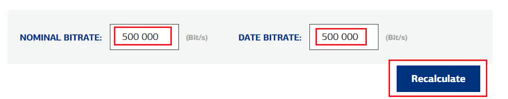
Next we have to input the bitrates that we want to set for the CAN.
As I already mentioned the FD CAN can transfer arbitration field and data filed at different bitrates. But I want to use the same bitrate for both of them, and that would be 500 Kbps. After you have entered the bitrates, click recalculate to calculate the values.
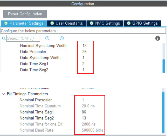
After we click the recalculate button, we will get the values of the parameters. This is shown in the picture below
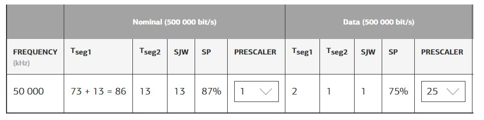
We can input these values in the FDCAN parameters.

Now we will see the rest of the parameters. The arrows shows the parameters which has been modified.
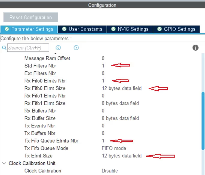
- In the image above, the message Ram offset is set to 0. This is used in the multiple instances of the FDCAN and will be covered in the next tutorial
Std Filters Nbris the number of standard (ID) filters we are using.- We can use up to 128 different filters configured to accept or reject messages from different IDs
- I am only using a single filter.
Ext Filters Nbris set to 0 because we are not using any Extended IDs in this tutorial- We will use the RX FIFO 0 to receive the message. Totally we can use up to 64 FIFO elements and each element can store up to 64 bytes of data.
- Here I am only using a single element to receive 12 bytes of data.
- I am not using any RX buffer or TX buffer, so all those parameters are set to 0.
- TX Fifo will be used to send the data to the CAN bus. So here I am using 1 element of the TX Fifo to send 12 bytes of data.
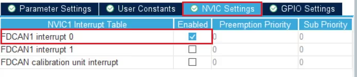
One last thing we need to do is enable the RX Fifo 0 interrupt. This interrupt will trigger whenever we receive a new message in the RX Fifo 0.
This completes the setup for the FDCAN. Now we will take a look at the code.
The Filter Configuration
Just like the regular CAN, we have filters in FDCAN too. The things are a bit more complicated here since there are many types of filters available. Let’s take a look at them
There are 4 types of filter available in FDCAN:
- RANGE Filter, which filters the messages coming from the IDs in range between ID1 and ID2
- DUAL Filter, which filters the messages specifically from the two IDs, ID1 and ID2
- MASK Filter, which filters the messages based on the ID (ID1) and Mask (ID2). This is similar to what we did in the CAN tutorial and we will be following this one today.
- RANGE Filter without External IDs, which filters just like the normal Range filter but here the External IDs will not be filtered.
Other than the types of filters, we also have the Filter Configuration. This field decides what should be done with the filtered messages. For example, should the messages be sent to FIFO, or should they be rejected, or marked as the High Priority messages, etc.
Basically you can configure multiple filters at the same time and each filter configuration will be stored in a separate filter index.
In this tutorial, I am going to use the Mask filter, and the filtered messages will be sent to fifo. Below is the configuration for the same.
  FDCAN_FilterTypeDef sFilterConfig;

  sFilterConfig.IdType = FDCAN_STANDARD_ID;
  sFilterConfig.FilterIndex = 0;
  sFilterConfig.FilterType = FDCAN_FILTER_MASK;
  sFilterConfig.FilterConfig = FDCAN_FILTER_TO_RXFIFO0;
  sFilterConfig.FilterID1 = 0x11;
  sFilterConfig.FilterID2 = 0x11;
  sFilterConfig.RxBufferIndex = 0;
  if (HAL_FDCAN_ConfigFilter(&hfdcan1, &sFilterConfig) != HAL_OK)
  {
    /* Filter configuration Error */
    Error_Handler();
}- The IdType defines if we are using the Standard IDs or Extended IDs
- Filterindex is used in case of configuring the multiple filters. Since I am only using 1 filter, it is set to 0.
- FilterType is the type of filter we are using. As I mentioned before, I am using the MASK Filter.
- For this MASK Filter, the ID1 (0x11) will act as the ID and ID2 (0x11) will act as the mask bits.
- If you want to learn more about how this works, I would suggest that you watch https://youtu.be/JfWlIY0zAIc
- FilterConfig decides what should be done to the messages that pass through the filter. It is set to be sent to RX FIFO 0.
- RxBufferIndex is used if you use the RX Buffer instead of FIFO, so it is set 0 her.
Finally ConfigFilter function will configure the above set filter.
The Code
We will start with some definitions.
FDCAN_TxHeaderTypeDef   TxHeader;
FDCAN_RxHeaderTypeDef   RxHeader;
uint8_t               TxData[12];
uint8_t               RxData[12];
int indx = 0;- Here I have defined the Headers and buffers for the TX and RX
- The index variable will be incremented later in the code.
In the main function we will start the FDCAN and set the notification for the new message in the RX Fifo 0.
  if(HAL_FDCAN_Start(&hfdcan1)!= HAL_OK)
  {
	  Error_Handler();
  }
  if (HAL_FDCAN_ActivateNotification(&hfdcan1, FDCAN_IT_RX_FIFO0_NEW_MESSAGE, 0) != HAL_OK)
  {
    /* Notification Error */
    Error_Handler();
}Here FDCAN_IT_RX_FIFO0_NEW_MESSAGE is the interrupt flag. Which basically enables the interrupt for the new message in the RX FIFO 0.
When the new message arrives in the RX FIFO 0, the interrupt handler gets called. We will handle the received data inside this interrupt handler.
void HAL_FDCAN_RxFifo0Callback(FDCAN_HandleTypeDef *hfdcan, uint32_t RxFifo0ITs)
{
  if((RxFifo0ITs & FDCAN_IT_RX_FIFO0_NEW_MESSAGE) != RESET)
  {
    /* Retreive Rx messages from RX FIFO0 */
    if (HAL_FDCAN_GetRxMessage(hfdcan, FDCAN_RX_FIFO0, &RxHeader, RxData) != HAL_OK)
    {
    /* Reception Error */
    Error_Handler();
    }
    if (HAL_FDCAN_ActivateNotification(hfdcan, FDCAN_IT_RX_FIFO0_NEW_MESSAGE, 0) != HAL_OK)
    {
      /* Notification Error */
      Error_Handler();
    }
  }
}- Here we will copy the message header into the RXHeader and message data into the RxData.
- We will activate the notification again as the interrupt gets disabled after each call.
In the main function we will configure the TX Header before sending the message to the CAN Bus.
  TxHeader.Identifier = 0x11;
  TxHeader.IdType = FDCAN_STANDARD_ID;
  TxHeader.TxFrameType = FDCAN_DATA_FRAME;
  TxHeader.DataLength = FDCAN_DLC_BYTES_12;
  TxHeader.ErrorStateIndicator = FDCAN_ESI_ACTIVE;
  TxHeader.BitRateSwitch = FDCAN_BRS_OFF;
  TxHeader.FDFormat = FDCAN_FD_CAN;
  TxHeader.TxEventFifoControl = FDCAN_NO_TX_EVENTS;
TxHeader.MessageMarker = 0;- The Identifier is the ID of the Transmitter, which is going to be 0x11
- The IdType is set to Standard ID as we are not using Extended ID in this tutorial.
- TxFrameType implies whether we are sending a Data frame or Remote frame. It is set to Data Frame.
- DataLength is set to 12 bytes. This is the length of the actual Data we are going to send.
- ErrorStateIndicator is active and it will notify us if there is any error in transmission.
- BitrateSwitch is OFF, as I mentioned we will be using the same bitrate for both Arbitration and Data Fields
- FDFormat implies whether you want to use the standard CAN or FD CAN. It is set to FD CAN
- We are not using the TxEvent or MessageMarker.
In the while loop we will send data at an interval of 1 second
while (1)
{
 for (int i=0; i<12; i++)
 {
  TxData[i] = indx++;
 }

 if (HAL_FDCAN_AddMessageToTxFifoQ(&hfdcan1, &TxHeader, TxData)!= HAL_OK)
 {
  Error_Handler();
 }

 HAL_Delay (1000);
}- Here we will first populate the TxData Array with the integral values.
- Then the function
HAL_FDCAN_AddMessageToTxFifoQwill add the message to the FIFO queue. - Once the message is added to the FIFO Queue, the message will be transferred to the CAN Bus
- Finally a delay of 1000 ms will keep the loop repeating every 1 second.
Result
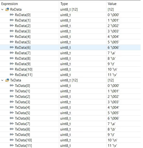
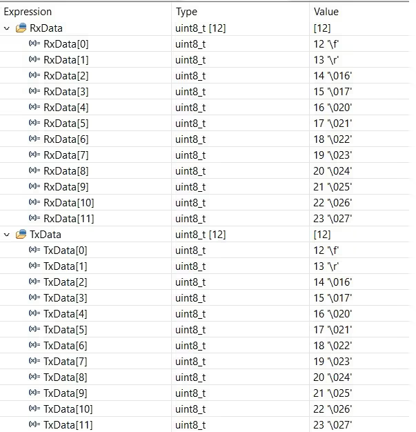
Below are the images captured from the Live Expression in the Debugger. You can see the TxData and RxData have the same values.
We are updating the Data in the TxData, which is then received by the FIFO and transferred to the RxData.
Other STM32 CAN Tutorials

Subscribe
Login
0 Comments
Newest
