How to measure input PWM signal in STM32
PWM (Pulse Width Modulation) signals are commonly used in embedded systems to represent information such as speed, position, or sensor data. In many real-world applications, it is not enough to generate a PWM signal — we also need to measure it. This includes finding the signal’s frequency and duty cycle accurately using the microcontroller.
In this second tutorial in the STM32 Timer Series, we will learn how to read a PWM input signal using an STM32 microcontroller. We will configure the timer in PWM input mode using STM32CubeMX and then use HAL functions to capture the signal’s high time and period. By the end of this tutorial, you will understand how to calculate the duty cycle and frequency of an incoming PWM signal and use this technique in applications such as motor feedback, RC receiver input, and signal monitoring.
PWM Signal Basics and PWM Input Working in STM32
What Is a PWM Signal?
PWM (Pulse Width Modulation) is a digital signal that alternates between HIGH and LOW states, but instead of varying voltage, it varies time.
A PWM signal is defined by three main parameters:
- Period – Total time taken for one complete cycle
- Frequency – How often the signal repeats (Frequency = 1 / Period)
- Duty Cycle – Percentage of time the signal stays HIGH in one period
Why these matter
- Duty cycle often represents power, speed, or position
- Frequency defines how fast the control or data updates
- Many peripherals (ESCs, motors, RC receivers) encode information using PWM
This makes PWM a very common signal type that needs to be measured, not just generated.
How PWM Input Works in STM32
STM32 microcontrollers measure PWM signals using timers, which are high-resolution hardware counters.
- Timers continuously count at a known clock frequency
- The counter value represents elapsed time
- This allows precise time measurement between signal edges
Measuring Duty Cycle and Frequency
STM32 uses both edges of the PWM signal:
- Rising edge → Falling edge
- Measures HIGH time
- Rising edge → Next rising edge
- Measures total period
Using these two values:
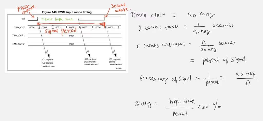
- Duty Cycle = (High Time / Period) × 100
- Frequency = Timer Clock / Period
This method is fully hardware-assisted, accurate, and efficient, making it ideal for reading PWM signals in real-time applications before moving on to the firmware implementation.
STM32 CubeMX Configuration
Clock Configuration
The image below shows the STM32 clock configuration.
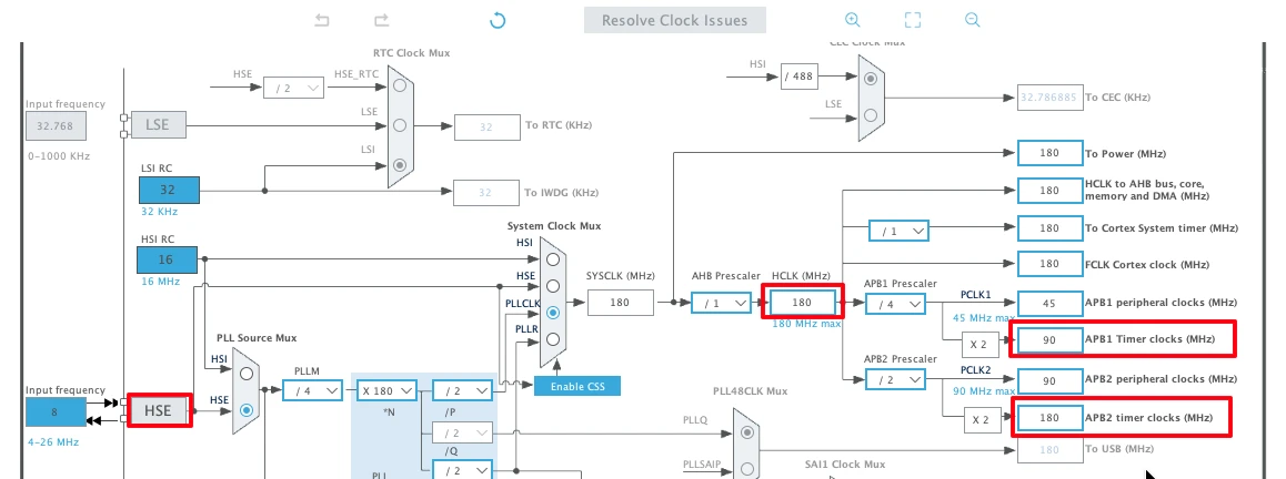
The Nucleo-F446 has 8MHz crystal shared between ST-Link and the main MCU. We will use this 8MHz crystal along with PLL to generate the system clock.
- The system is running at 180 MHz
- The APB1 Timer clock (TIMER 2 Clock) is at 90 MHz
- The APB2 Timer Clock (TIMER 1 Clock) is at 180 MHz
Timer 1 Configuration (PWM out for Testing)
To measure the input PWM signal, we need a PWM signal. I am going to use the TIM1 to generate one. This will be useful as we will already know the pulse width and frequency, making it easier for us to debug any issue with the measured pulse.
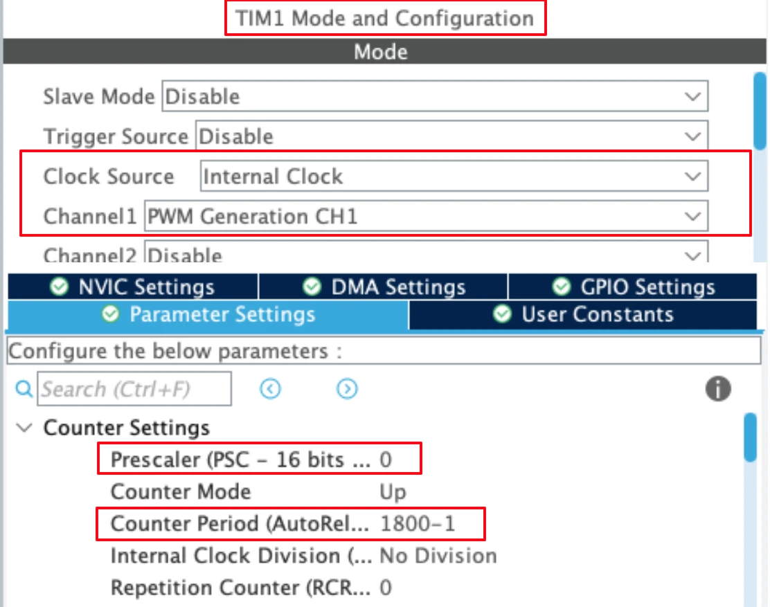
- We already know that the APB2 Timer Clock is running at 180 MHz.
- Using the Auto Reload Value (ARR) of 1800, along with the prescaler of 1 (0 in the configuration) will set the PWM output Frequency at 100 KHz.
- The channel 1 is being used as the PWM Out channel.
- The duty cycle part will be covered in the code itself.
I have already covered how to generate the PWM with STM32. If you have any issues understanding these parameters, check out the linked tutorial.
Note:
Calculate the ARR and CCR values for the STM32F4 Timers using the STM32F4 PWM Tool:
https://controllerstech.com/tools/stm32f4-pwm-calculator/
Timer 2 Configuration (PWM Input)
Timer 2 will be used to measure the incoming signal. The image below shows the Timer 2 configuration for PWM input mode.
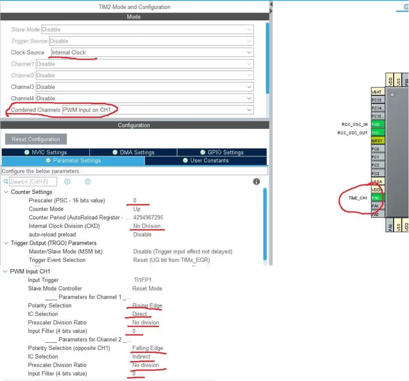
- The clock source is internal clock.
- The combined channels has been selected in the PWM Input mode on channel 1
- Note that only one Pin (PA0) has been selected as the input Pin, it is actually the channel 1 pin
- The channel 2 is internally connected to the channel 1, and this is to measure the duty cycle
- The prescalar is 0, so the timer clock will be same as APB 1 Timer clock, that is 90 MHz
- The polarity for the channel 1 is set to the rising edge, and it is set to falling edge for the channel 2.
- The IC Selection for the Channel 1 is direct, and here we are going to connect our input signal (PA0)
- The IC selection for the channel 2 is inDirect, and it is internally connected to the channel 1.
- The rest of the configuration is explained below
Internal Clock Division
This field indicates the division ratio between the timer clock (CK_INT) frequency and the dead-time and sampling clock (tDTS) used by the dead-time generators and the digital filters (ETR, TIx)
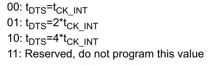
In the main setup, I have set it to NO DIVISION. This means the Sampling Clock will be same as the Internal clock, i.e. 90 MHz
Prescaler Division Ratio
This bit basically defines how often we want to do the capture on the input signal.
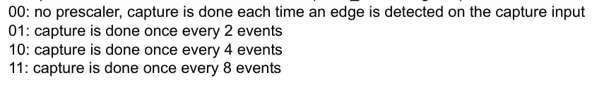
The CubeMX did not let me configure this part. But I will configure it later in the main code.
Setting this to 8 events would make it easier for the rest of the code to run. This way the captures will be limited, and less number of interrupts will be triggered.
Input Filter
This basically defines the sampling frequency. Also how many events does it take to validate a transaction.
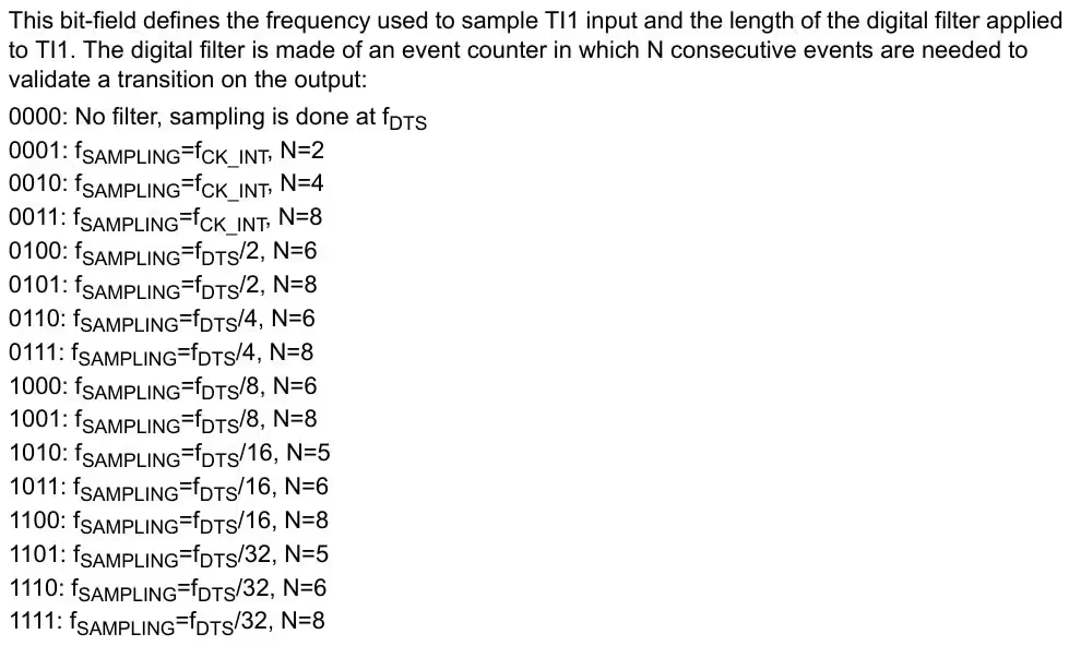
The IC Filter configures the Sampling Frequency. It also configures the low pass filter, but I will update the information about that some other day.
For now I am choosing the filter as 0, so the Fsample = FDTS , which will be same as the internal clock.
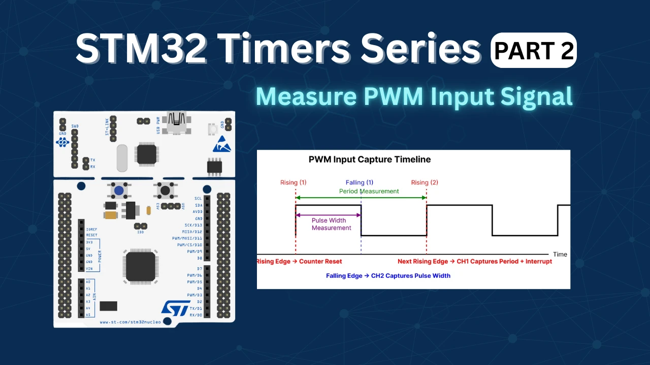
How PWM Input Works
PWM Input mode measures the characteristics of an incoming PWM signal by monitoring its edges. The timer uses two capture channels that observe the same input signal but react to different edges. This allows the timer to measure both the total signal period and the duration for which the signal stays high.
When the timer detects the first rising edge of the PWM signal, it resets the timer counter to zero. This marks the start of a new measurement cycle. As the timer continues counting, it waits for the falling edge of the signal. When the falling edge occurs, the timer captures the counter value using the second channel. This captured value represents the pulse width, which is the time duration for which the signal remained high.
The timer then continues counting until the next rising edge of the PWM signal is detected. At this moment, the first channel captures the counter value again, which represents the complete period of the PWM signal. Immediately after capturing the period, the timer resets the counter again to begin measuring the next cycle. The interrupt is typically generated at this rising edge, because at that instant both the pulse width and the period values from the same signal cycle are available.
The image below shows the timing sequence of PWM Input mode, illustrating how the timer resets on the rising edge, captures the pulse width on the falling edge using Channel 2, and measures the signal period on the next rising edge using Channel 1.
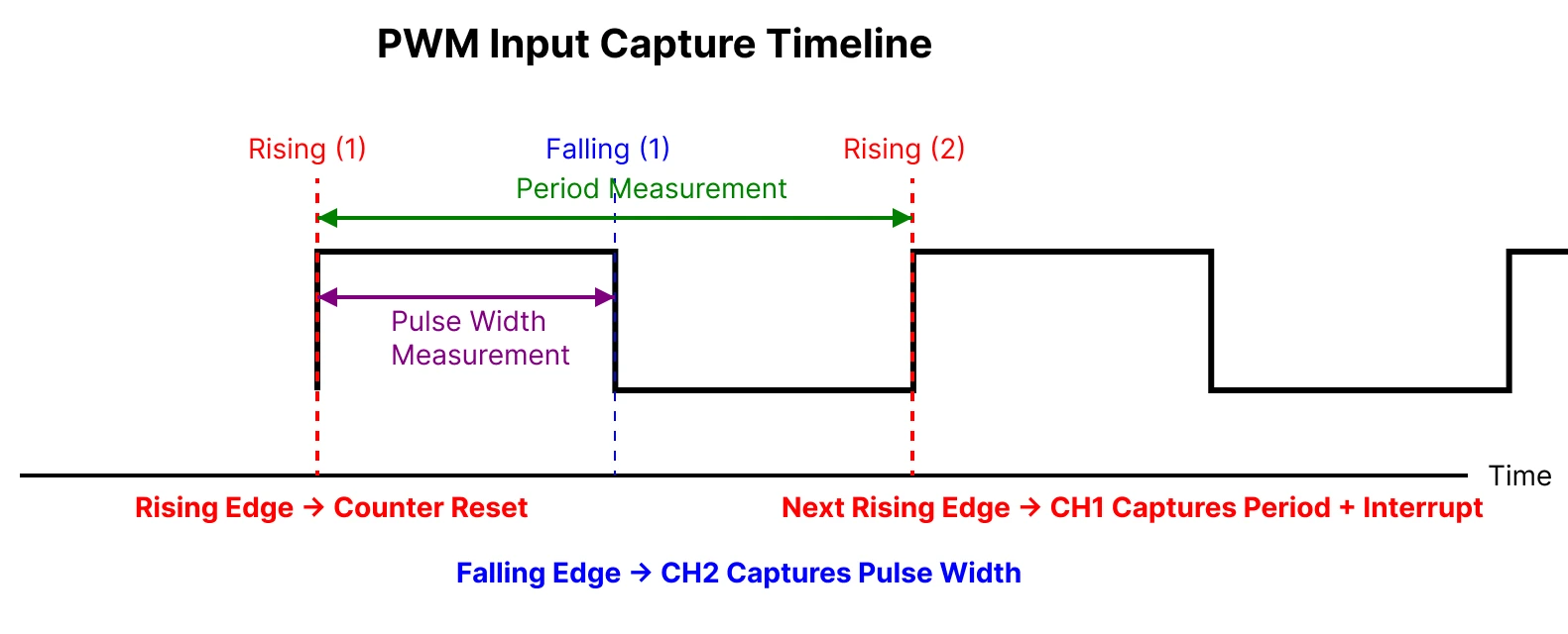
This sequence ensures that both measurements are synchronized and belong to the same PWM cycle. Using these captured values, the duty cycle is calculated by dividing the pulse width by the total period, while the signal frequency is calculated using the timer clock and the captured period value.
STM32 Code to measure PWM Input
We need a PWM signal in order to measure one. Therefore we will first start with Generating the PWM output with TIM1. I have already covered it in the previous part of this series, so do check it out.
Generate PWM signal
Before we capture the PWM input signal, we need to generate it using Timer 1. Inside the main function, we will simply start the Timer 1.
  HAL_TIM_PWM_Start(&htim1, TIM_CHANNEL_1);
TIM1->CCR1 = 900;Here I am starting Timer 1 in the PWM mode. The Capture Compare Value is set to 900. With the ARR of 1800, this will generate a pulse with the duty cycle of 50% [(900/1800)*100].
We will measure this signal using the Timer 2 PWM Input Mode.
Start Timer 2
Inside the main function, we will start the TIM2 in the input capture mode. We need to start both the channels, even though the signal pin is connected to only one of them.
HAL_TIM_IC_Start_IT(&htim2, TIM_CHANNEL_1);   // main channel
HAL_TIM_IC_Start(&htim2, TIM_CHANNEL_2); // indirect channel- Here I am starting the input capture for the Channel 1 in the interrupt mode, and channel 2 in the normal mode.
- This way the interrupt handler will only be called, when the rising edge gets captured. And that much is enough to get it working.
Once the rising edge is captured, the Input Capture callback will be called, and we will write the rest of the code inside it.
Input Capture Callback
We will do our entire calculation inside the HAL_TIM_IC_CaptureCallback function.
#define TIMER_CLOCK		90000000
uint32_t Frequency = 0;
float Duty = 0;


void HAL_TIM_IC_CaptureCallback(TIM_HandleTypeDef *htim)
{
    if (htim->Channel == HAL_TIM_ACTIVE_CHANNEL_1)
    {
        uint32_t period = HAL_TIM_ReadCapturedValue(htim, TIM_CHANNEL_1);
        uint32_t pulse  = HAL_TIM_ReadCapturedValue(htim, TIM_CHANNEL_2);

        if (period != 0)
        {
            Duty = ((float)pulse * 100.0f) / period;

            Frequency = (float)TIMER_CLOCK / period;
        }
    }
}TIMER_CLOCK is the actual clock frequency driving TIM2 (The one which is measuring the input signal). It must be defined because the timer measures time in clock ticks, and this value is required to convert the captured timer counts into real signal frequency and duty cycle.
- Inside the callback function, we read the input capture values from both channels and store them in local variables representing the period and the pulse width.
- During the first rising edge, the timer counter gets reset, so the captured period value may not be valid for measurement. From the next cycle onward, the capture on Channel 1 provides a non-zero value, which represents the complete period of the incoming PWM signal.
- At the falling edge of the signal, Channel 2 captures the counter value, which represents the duration for which the signal remained in the HIGH state. This captured value is used as the pulse width of the signal.
- The duty cycle of the PWM signal is calculated by dividing the pulse width by the period of the signal. The frequency of the input signal is calculated by dividing the timer clock frequency by the captured period value.
The calculation used in the code above is explained below with the figure from the reference manual.
Result of the PWM input Capture
The image below shows the result captured on the STM32CubeIDE Debugger console.
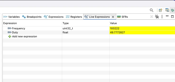
The Frequency is around 100 KHz, and the Duty Cycle is 49.7%. This is the same duty and Frequency generated by the TIM1.
VIDEO Tutorial
STM32 PWM Input Tutorial Video
This tutorial explains how to read and measure a PWM input signal using STM32 microcontrollers. Along with the written guide, this video walks through the timer configuration in CubeMX, input capture setup, and the HAL code used to calculate the duty cycle and frequency of an incoming PWM signal. Watch the video to clearly understand how PWM input works at both the hardware and code level.
Watch the VideoConclusion
In this tutorial, we covered how to read a PWM input signal using an STM32 microcontroller by configuring the timer in input capture mode. We discussed the basics of PWM signals, explained how STM32 timers use rising and falling edges to measure time, and walked through the CubeMX configuration and HAL-based code needed to capture the signal accurately. By measuring the high time and total period, we were able to calculate both the duty cycle and frequency of the incoming PWM signal.
Understanding PWM input is extremely useful in many real-world embedded applications where external devices communicate using PWM. This technique can be applied to read signals from RC receivers, motor controllers, sensors, and feedback systems without additional hardware. Since the measurement is handled by the timer peripheral, it is both precise and efficient, making it suitable for real-time applications and forming a strong foundation for more advanced timer-based features in STM32 projects.
Checkout More STM32 Timer Tutorials
STM32 Timers (Part 3): How to use the Timer Encoder Mode
STM32 Input Capture: Measure Frequency & Pulse Width
STM32 Timer Synchronization: Slave Trigger Mode with CubeMX & HAL
STM32 Timers (Part 6): Timer Synchronization for 3-Phase PWM Generation
STM32 Timers (Part 7): Timer synchronization using Slave Reset mode
STM32 Timers (Part 8): How to Create a 48-Bit Counter by Cascading Timers
STM32 Timers (Part 9): One Pulse Mode (OPM) – Generate Precise Triggered Pulses with Delay and Width Control
STM32 PWM Input Project Download
STM32 PWM Input FAQs


I test this code in STM32F103C8T6 Chinese clone, controller, and i was able to made it batter even without DMA:
First i modify IRQ interrupt callback to:
volatile uint32_t period;
volatile uint32_t pulse;
void TIM2_IRQHandler(void)
{
if (TIM2->SR & TIM_SR_CC1IF)
{
TIM2->SR &= ~TIM_SR_CC1IF;
period = TIM2->CCR1;
TIM2->SR &= ~TIM_SR_CC2IF;
pulse = TIM2->CCR2;
}
}
and next i calculate in main loop:
while (1)
{
/* USER CODE END WHILE */
HAL_Delay(500);
if (period != 0)
{
Duty = ((float)pulse * 100.0f) / period;
Frequency = (float)TIMER_CLOCK / period;
}
/* USER CODE BEGIN 3 */
}
it work fine even on 4MHZ, but i always have stable mistake in 2 CPU tick. even if i set Prescaler TIM2 to 1 i have difference in 1 timer tick, if i set 0 – i get 2 tick. Independent what freq i use. But on 4MHZ it is too big mistake, because i have only 18 tick per period.
As I understand timers 1, 8, 9, 10, 11 are connected to APB 2 and 2, 3, 4, 5, 6, 7, 12, 13, 14 to APB 1
Yes you are correct, that is a typing mistake. I will fix it.
When I use the ADC value to dynamically change the pulse value of Timer 1 Channel 1 (
__HAL_TIM_SET_COMPARE(&htim1, TIM_CHANNEL_1, adc_value );), why doesn’t the duty cycle change? That is,HAL_TIM_ReadCapturedValue(htim, TIM_CHANNEL_2)does not change along with the ADC value.I observed the PWM generated by Timer 1 Channel 1 using a logic analyzer, and it indeed changes according to the ADC value.
chibba chibba
If I change the prescaler of TIM2, can I measure lower frequcy PWM
Is it possible to simulate this example with Proteus (PWM/Timers) for F103 or F401 ?
Thank you for all STM32 tutorials
Hi, do u know how to setup it by DMA?
Input pin Only connected to channel 2.
If u are getting Ic_VAl2 as 0, use channel 3 in indirect mode. However i will advice not to use this. There are 2 more posts on how to measure pulse width and frequency. Use them.. i was supposed to delete this post but forgot.
Sir, In your code IC_Val2, is not getting updated. Hence duty cycle is zero. Also How falling is detected?
Did you followed the steps correctly? As shown above it detects falling edge. I wouldn’t prefer this method though. Look for another tutorial “measure pulse width using input capture”. That is more effective