Updated On: March 23, 2026
STM32 One Pulse Mode (OPM) – How to Generate a Single Triggered Pulse
In many embedded applications, we don’t need a continuous PWM signal — we only need one precise pulse generated exactly when an event occurs. For example, triggering an ultrasonic sensor, generating a gate pulse, producing a timed output after an input edge, or creating a controlled delay followed by a pulse.
This is where STM32 One Pulse Mode (OPM) becomes extremely powerful. In this mode, the timer waits for a trigger event and then generates a single pulse with programmable delay and pulse width, after which it automatically stops. In this tutorial, we’ll understand how One Pulse Mode works internally, how ARR and CCR define delay and width, how to configure it in STM32CubeMX, and how to verify the output timing using an oscilloscope.
What is One Pulse Mode (OPM) in STM32?
One Pulse Mode (OPM) is a special timer operating mode in STM32 that allows the timer to generate a single output pulse in response to a trigger event. Unlike standard PWM, which runs continuously, OPM produces only one pulse and then automatically stops.
This makes it ideal for applications where a precisely timed pulse must be generated only when required, such as ultrasonic triggering, stepper motor control, external device activation, or event-based timing measurements.
How One Pulse Mode Works
In One Pulse Mode, the timer remains idle until a valid trigger event is received (internal or external). Once triggered:
- The counter starts running.
- After a programmable delay, the output changes state.
- The output remains active for a programmable pulse width.
- After completing the pulse, the timer automatically stops.
Both the delay before the pulse and the pulse width are configurable using the timer registers (ARR and CCR).
Controlling Pulse Delay and Pulse Width
In OPM, two parameters define the waveform:
- Pulse Delay → Controlled by the Compare Register (CCR)
- Pulse Width → Determined by the difference between ARR and CCR (depending on configuration)
This allows precise control over:
- When the pulse starts
- How long the pulse remains active
Because STM32 timers are hardware-based, this timing is extremely accurate and does not depend on software delays.
Single Pulse vs Continuous Pulse Train
One Pulse Mode can be configured in two ways:
- Single Pulse Mode
A single trigger produces one pulse, and the timer stops automatically. - Continuous Pulse Mode (Triggered PWM)
A single trigger can start a continuous PWM signal if OPM is disabled. This is useful when you want hardware-triggered continuous operation instead of a single pulse.
The key difference is whether the timer automatically stops after one cycle.
Retriggerable One Pulse Mode
STM32 timers also support a retriggerable option.
In retriggerable mode:
- If a new trigger arrives before the pulse finishes,
- The counter is reset,
- The pulse duration is extended accordingly.
This is useful in applications like:
- Pulse stretching
- Frequency-to-pulse-width conversion
- Event timing where overlapping triggers must extend the output
Retriggerable OPM ensures the output remains active as long as triggers keep arriving within the pulse duration.
This timing diagram illustrates STM32 Timer One Pulse Mode in Trigger Mode using TI2 as the input trigger and OC1 as the output channel.
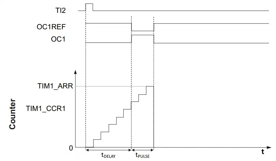
When a rising edge appears on TI2, the timer counter (CNT) starts counting from zero. The counter increases step-by-step until it reaches the value stored in TIM1_CCR1, which defines the output compare point.
- The time from the trigger event to when the output changes state is labeled as tDELAY — this is the programmable delay (defined by CCR1).
- When the counter reaches CCR1, OC1REF becomes active, and the output OC1 changes accordingly.
- The counter continues counting until it reaches TIM1_ARR, which defines the end of the pulse.
- The duration between CCR1 and ARR is labeled as tPULSE, which represents the programmable pulse width.
- After reaching ARR, the timer stops automatically, completing a single pulse.
This clearly shows how both the pulse delay and pulse width are independently controlled using CCR1 and ARR.
STM32CubeMX Configuration
In this section, we will set up the timer in One Pulse Mode with Trigger Mode enabled, configure the input trigger source (TI2), and set the output channel (OC1) to generate the pulse. We will also adjust the prescaler, ARR, and CCR values to achieve the required timing.
Clock configuration
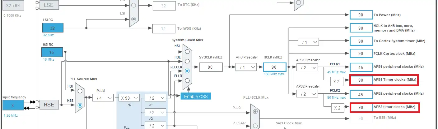
I have configured the 8 MHz external crystal to provide the clock. The system is running at 90MHz and note that both the APB timer clocks are also running at 90MHz. This will make us easier to configure the timer as we don’t have to worry which timer is connected to which APB bus.
Timer configuration
I am using TIM1 for this application. The setup is shown below.
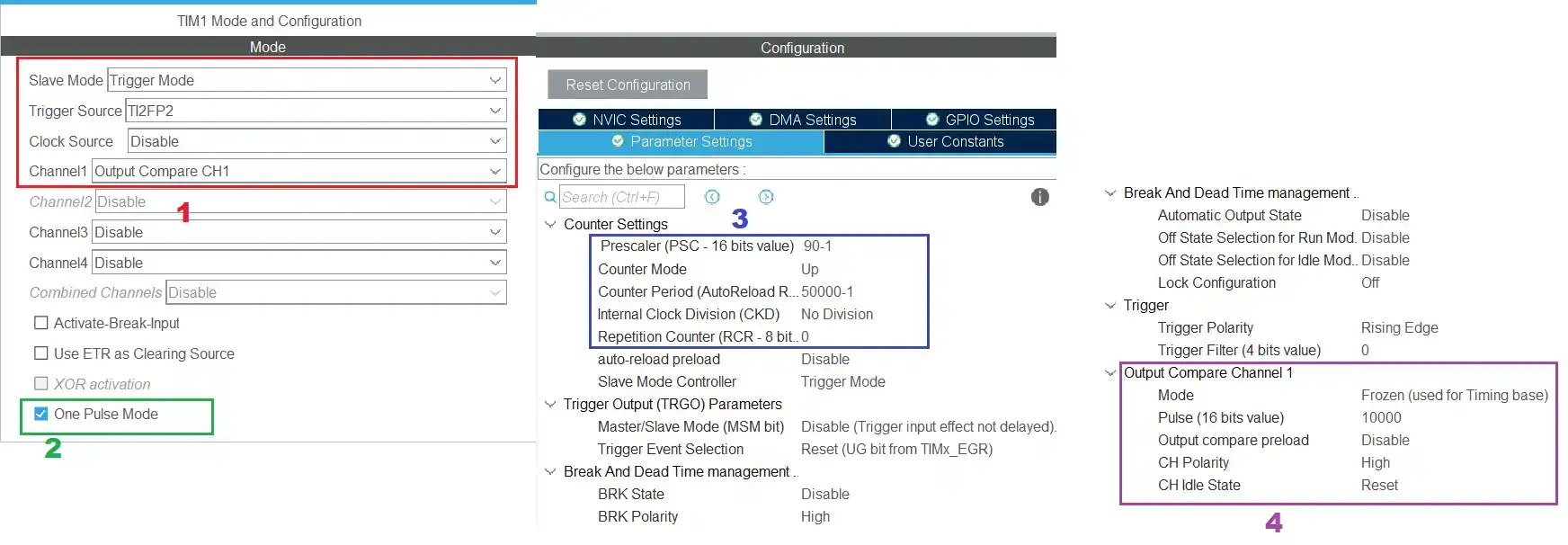
- The timer must be configured in the slave mode with trigger mode.
- I have selected the trigger source as TI2FP2, i.e the channel 2 of the timer. Here we will connect the signal pin.
- The channel 1 is used for the output compare. Here we will get the output from the timer.
- Make sure to select the one pulse mode.
- The prescalar of 90 will bring down the clock to 1MHz. This is the rate at which the counter counts and each count will take 1us.
- I have set the ARR to 50000, so the maximum width of the pulse can be 50ms.
- Also note that the Repetition counter is set to 0, which means we only want a single pulse. If you set this value to 10 (11-1), there will be 11 pulses for each trigger.
- The Mode in output compare will be changed later in the code.
- The pulse value (the CCR1 value) is set to 10000. This means the pulse will be delayed by 10000 counts, i.e. 10ms after the trigger.
The above configuration will generate a pulse of 40ms (ARR – CCR) on each trigger on channel 2 of the timer 1.
Note:
Calculate the ARR and CCR values for the STM32F4 Timers using the STM32F4 PWM Tool:
https://controllerstech.com/tools/stm32f4-pwm-calculator/
We are using 2 channels for the timer 1, below is the pinout for the same.
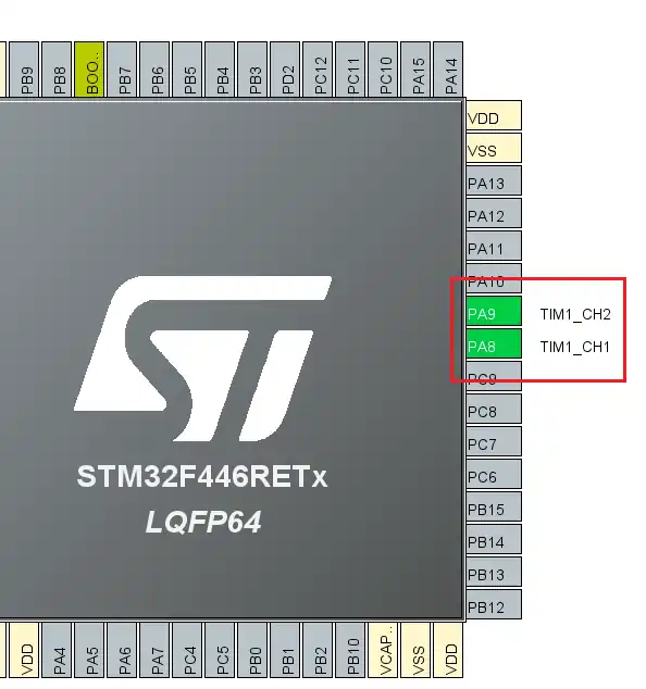
Here the pin PA9 (TIM1_CH2) will be used as the input pin, where we will send the external signal. And the pin PA8 (TIM1_CH1) will be used as the output pin, where the one pulse will be generated. We will monitor this on the oscilloscope.
Generating Multiple pulses
The above configuration will only generate a single pulse of the predefined delay and pulse width. If you want to generate a pulse train on a single trigger signal, you have to write the value in the Repetition counter. This is shown below.
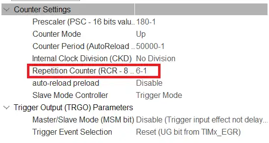
The rest of the configuration is still the same. I have only modified the Repetition counter value to 5 (6-1). This arrangement will generate the 6 pulses of the same width upon receiving a trigger signal on the channel 2.
Retriggerable One Pulse Mode
In the Retriggerable mode, a new trigger arriving before the end of the pulse will cause the counter to be reset and the pulse width to be extended accordingly. The setup for the Retriggerable mode is shown below.
Note:
All the STM32 MCUs don’t have the retriggerable option. I am using STM32F750 discovery board and it have the retriggerable mode.
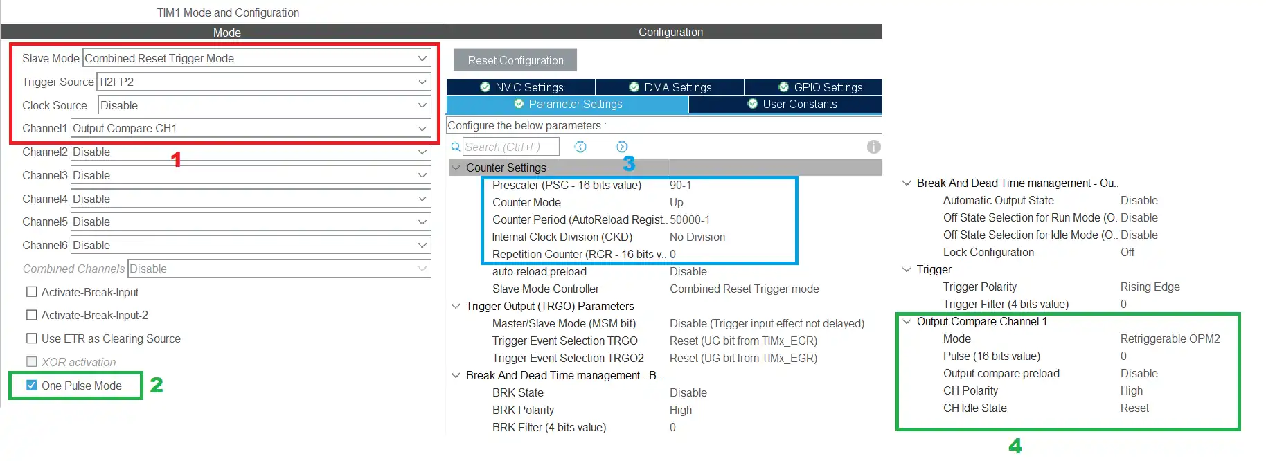
- The timer must be configured in the slave mode with Combine Reset and trigger mode. The reset of the configuration is same as what we configured earlier.
- Make sure to select the one pulse mode.
- The Prescalar and ARR configuration is same as what we configured earlier.
- The Mode in output compare is set to Retriggerable One pulse mode 2.
- The pulse value must be set to 0.
Wiring Diagram for the One Pulse Mode
The image below shows the wiring connection used in this project.

In the picture above you can see that the BLACK wire is connected between the button and the pin PA9, the TIM_CH2 Pin. The PURPLE wire is connected between the button and the 3.3V pin on the MCU.
When the button is pressed, the input pin, PA9, is pulled up to 3.3V and the Timer will see this as the trigger signal.
The BLUE wire is connected between the pin PA8, TIM_CH1, and the Logic analyzer. This is the output pin, so we will use it to see the one pulse generated on the Logic Analyzer.
STM32 HAL Code for One Pulse mode
Once the timer has been configured in STM32CubeMX, the next step is to initialize and start it using the STM32 HAL functions. In One Pulse Mode, the timer remains idle until a valid trigger event occurs, after which it generates a single pulse and stops automatically. In this section, we’ll look at the essential HAL functions required to configure and start One Pulse Mode properly.
Generate a Single Pulse
Inside the MX_TIM1_Init() function, we need to slightly modify the Output Compare configuration.
Change the Output Compare mode to PWM2:
sConfigOC.OCMode = TIM_OCMODE_PWM2;PWM2 mode is used here because it generates an output pulse that becomes active only after the counter reaches the CCR value, and remains active until the counter reaches ARR.
This means:
- The output stays LOW from 0 → CCR (this is the delay period).
- The output becomes HIGH from CCR → ARR.
- When ARR is reached, the timer stops (since we are using One Pulse Mode).
Therefore, the pulse width is effectively: Pulse Width = ARR − CCR
For the remaining duration outside this interval, the signal stays LOW, which perfectly matches the timing behavior required in One Pulse Mode.
Inside the main function, after the timer initialization is over, start the timer in one pulse mode.
  /* USER CODE BEGIN 2 */

  HAL_TIM_OnePulse_Start(&htim1, TIM_CHANNEL_1);

/* USER CODE END 2 */Output of Single Pulse
Below is the image showing the output on the logic analyzer.
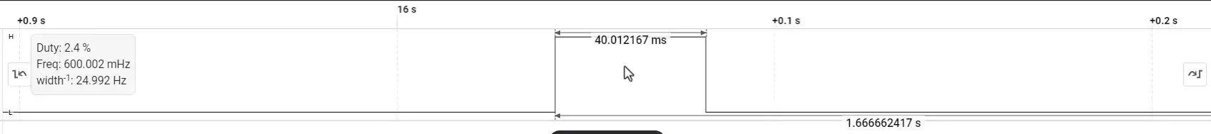
The image above shows a single pulse of 40ms was generated when the button was pressed.
This is as per the setup we did in the cubeMX for the timer, with ARR at 50000(50ms) and CCR at 10000(10ms). The difference between them is 40ms and that is the width of the pulse.
Generating Multiple Pulses
Now, suppose we want to generate 8 pulses using a single external trigger instead of just one pulse. To achieve this, we only need to modify one parameter in the timer initialization: the Repetition Counter.
htim1.Init.RepetitionCounter = 8-1;Since we want 8 pulses, we set the repetition counter to 7.
This is because the repetition counter works in a zero-based manner: Number of pulses = RepetitionCounter + 1
So,
RepetitionCounter = 7 → 8 pulses generatedHow This Works
When the external trigger arrives:
- The timer starts counting.
- It generates one PWM pulse (based on ARR and CCR).
- Instead of stopping immediately (as in single OPM),
the timer repeats the cycle according to the repetition counter. - After 8 update events, the timer automatically stops.
This means a single trigger event produces 8 consecutive pulses, and then the timer disables itself automatically.
What Remains Unchanged
- PWM mode is still PWM2
- Pulse delay is still defined by CCR
- Pulse width is still ARR − CCR
- Trigger configuration remains the same
- One Pulse Mode is still enabled
The only change required to convert a single pulse into multiple pulses is the RepetitionCounter value.
Output of Multiple Pulses
The images below show the output waveform when the timer is configured to generate multiple pulses using a single external trigger.
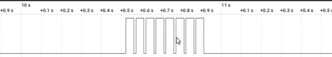
In the first image, a single trigger event produces 8 consecutive pulses, confirming that the repetition counter is working correctly. After the eighth pulse, the timer automatically stops, as expected in One Pulse Mode.
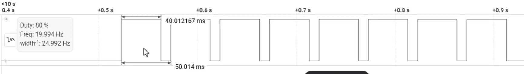
In the second image, the measured pulse width is 40 ms, and this value remains identical for all generated pulses. This verifies that while the repetition counter controls the number of pulses, the pulse timing itself is still determined by the configured ARR and CCR values.
Retriggerable Pulse Mode
In Retriggerable One Pulse Mode, the output pulse is extended if a new trigger event arrives while the pulse is still active (HIGH). Instead of ignoring the new trigger, the timer resets its counter and effectively increases the pulse duration. This allows the output to remain active as long as valid triggers continue to arrive within the pulse period.
For this demonstration, I am using the STM32F750 Discovery board, since retriggerable One Pulse Mode is not supported on all STM32 MCUs.
The trigger signal is generated from another GPIO pin, PA0, which is connected to TIMx_CH2 (the input channel 2 of the timer). By controlling the toggle timing of PA0 in software, we can precisely adjust when the trigger event occurs and observe how it affects the output pulse extension.
The configuration for enabling Retriggerable One Pulse Mode is shown below.
- The timer must be configured in the slave mode with Combine Reset and trigger mode. The reset of the configuration is same as what we configured earlier.
- Make sure to select the one pulse mode.
- The Prescalar and ARR configuration is same as what we configured earlier.
- The Mode in output compare is set to Retriggerable One pulse mode 2.
- The pulse value must be set to 0.
  while (1)
  {
	  HAL_GPIO_WritePin(GPIOA, GPIO_PIN_0, 1);
	  HAL_Delay(5);
	  HAL_GPIO_WritePin(GPIOA, GPIO_PIN_0, 0);
	  HAL_Delay(40);
}Remember that PA0 is physically connected to TIMx_CH2, which is the timer’s trigger input. Therefore, whenever PA0 is driven HIGH, the corresponding timer trigger input also sees a HIGH level and generates the trigger event (based on the configured edge).
In this configuration:
- ARR = 50000 → 50 ms
- CCR (Pulse value) = 0
Since we are using PWM2 mode with CCR = 0, the output becomes active immediately when the counter starts and remains active until it reaches ARR. Therefore, the output pulse width is 50 ms.
Now, inside the while loop, PA0 is toggled HIGH every 45 ms.
Notice that:
Trigger interval = 45 ms
Pulse width = 50 msBecause 45 ms is less than 50 ms, a new trigger arrives before the current pulse finishes.
In Retriggerable One Pulse Mode, this causes:
- The counter to reset.
- The timing cycle to restart.
- The output pulse to remain HIGH longer than the original 50 ms.
As a result, the pulse does not go LOW at 50 ms. Instead, its duration is extended each time a new trigger arrives before the previous pulse ends.
Output of the Retriggerable Pulse
The image below shows the output of the retriggerable pulse mode.

You can see in the image above, the pulse width has been extended. This is because the new trigger signal is arriving before the pulse can even go low, so it simply keep extending.
Video Tutorial
STM32 Timer One Pulse Mode (OPM) – Complete Video Tutorial
This video explains how to configure and use One Pulse Mode (OPM) in STM32 timers. You’ll learn how to generate a single pulse using an external trigger, control the pulse delay and width using ARR and CCR, and extend the setup to generate multiple pulses using the repetition counter. The step-by-step walkthrough covers CubeMX configuration, HAL implementation, oscilloscope testing, and even demonstrates Retriggerable One Pulse Mode for pulse extension applications.
Watch the VideoConclusion
In this tutorial, we explored how to use STM32 Timer One Pulse Mode (OPM) to generate precise, hardware-controlled pulses in response to an external trigger. We saw how the ARR and CCR registers define the pulse timing, where CCR controls the delay and ARR determines the total duration of the pulse.
We then extended the concept by using the Repetition Counter to generate multiple pulses from a single trigger event, allowing us to create a fixed number of consecutive pulses without any CPU intervention.
Finally, we demonstrated Retriggerable One Pulse Mode, where the pulse duration automatically extends if a new trigger arrives before the current pulse ends — a powerful feature for applications such as signal conditioning, timeout extension, and pulse stretching.
Browse More STM32 Timer Tutorials
STM32 Timers (Part 3): How to use the Timer Encoder Mode
STM32 Input Capture: Measure Frequency & Pulse Width
STM32 Timer Synchronization: Slave Trigger Mode with CubeMX & HAL
STM32 Timers (Part 6): Timer Synchronization for 3-Phase PWM Generation
STM32 Timers (Part 7): Timer synchronization using Slave Reset mode
STM32 Timers (Part 8): How to Create a 48-Bit Counter by Cascading Timers
STM32 Timers (Part 10): Timer in Gated Mode ‒ Control PWM and Counter with External Signals
STM32 One Pulse Mode Project Download
STM32 One Pulse Mode FAQs


can i configure this with complementary output like the same configuration with tim1 ch1 and ch1n
how to change this timer property at runtime htim1.Init.RepetitionCounter = 59 when using HAL_TIM_OnePulse_Init(&htim1, TIM_OPMODE_SINGLE) option
There are some properties which you can’t change during the runtime. I am not sure if RCR comes under that but you can try TIM1->RCR = value.
Is there a possibily of triggering the one-pulse from a HAL command from the software instead of an external input?
You are doing an amazing job. thank you very much
I would like to trigger the One Pulse timer from code. How could I do that?
Hello, thank you very much, Sir.