Generate PWM Output in STM32
Learn STM32 PWM setup using HAL and CubeMX. This tutorial will cover the timer prescaler & ARR configuration, controlling duty cycle via CCR, and starting PWM with sample code and visuals. The project is available for download at the end of the post.
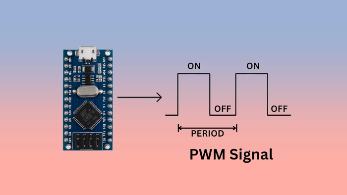
Introducing the Pulse Width Modulation
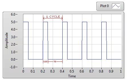
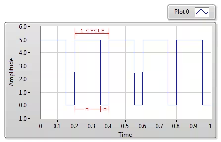
Pulse Width Modulation (PWM) is a technique used to control the amount of power delivered to electronic devices by varying the width (duration) of digital pulses. Instead of adjusting voltage levels directly, PWM rapidly switches the signal between ON and OFF states. The proportion of time the signal stays ON in one cycle is called the duty cycle, and it determines the effective power delivered to the load.
PWM is widely used in applications such as motor speed control, LED brightness, servo positioning, and digital-to-analog signal emulation. In microcontrollers like STM32, PWM signals are typically generated using timers configured with specific frequency and duty cycle values.
PWM consist of two main components:-
1.) Duty cycle
2.) Frequency
By cycling a digital signal ON and OFF at a fast enough rate and at a certain duty cycle, the output will appear like a constant voltage analogue signal. For eg: To create a 2V signal from a digital source which is either HIGH(5V) or low (0). We can use PWM with duty cycle of 40% here. This 40% duty cycle would yield an average voltage of 5×0.4=2V.
Important Features of PWM:
- Precise Duty Cycle Control
Allows fine-grained control over output power by adjusting the ON duration within each cycle. - Efficient Power Usage
Minimizes energy loss by switching devices fully ON or OFF, making it ideal for power-sensitive applications. - Wide Range of Applications
Used in motor control, LED dimming, audio modulation, signal generation, and more. - Timer-Based Hardware Generation
PWM is generated using internal timers in microcontrollers, ensuring accurate and consistent output without heavy CPU usage.
CUBEMX CONFIGURATION
I am using the famous STM32F103C8 (BluePill) for this project. We will start with the Clock Configuration.
Clock Configuration
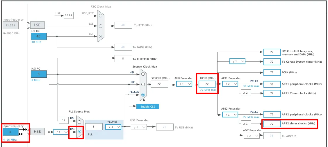
The clock configuration for the project is shown in the image below.
- External Crystal (8MHz) is used to provide the clock via the PLL and the system is running at maximum 72MHz clock.
- I am going to use the TIM1 for the PWM, which is connected to the APB2 Bus.
- The APB2 Timer clock is at 72MHz right now and that makes TIM1 clock = 72MHz.
PWM Configuration
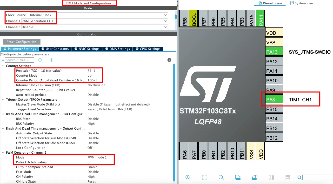
The Timer1 PWM configuration is shown in the image below.
The detailed description of the image is mentioned below.
Timer Setting
- Clock Source: Internal Clock
This sets the timer to use the internal APB2 clock as its source. It’s essential for generating precise time-based signals like PWM without relying on external clocks. - Channel1: PWM Generation CH1
This enables PWM output on Channel 1 of TIM1. It’s what makes the timer output a PWM signal rather than just counting.
Counter Settings
- Prescaler (PSC = 72-1)
This divides the timer’s input clock frequency by 72.
For example, if the APB clock is 72 MHz, the timer counts at 1 MHz after prescaling. - Counter Mode: Up
The timer counts from 0 up to the value in the AutoReload Register (ARR), then resets and starts over. This is the typical mode for PWM. - Counter Period (ARR = 100-1)
Sets the maximum count value (100 – 1 = 99), which defines the PWM frequency in combination with the prescaler.
PWM Frequency = Timer Clock / (PSC + 1) / (ARR + 1)
→ For 72 MHz APB clock:
→ PWM Frequency = 72 MHz / 72 / 100 = 10 kHz
PWM Generation Channel 1 Settings
- Mode: PWM mode 1
This sets the PWM output to PWM Mode 1, which means:- Output is HIGH when the counter is less than the pulse value.
- Output is LOW when the counter is greater than or equal to the pulse value.
- Pulse (CCR1) = 0
This defines the initial duty cycle — in this case, it’s 0, meaning no ON time.
The output will stay LOW until this value is changed in code.
Pin Mapping (PA8 – TIM1_CH1)
- PA8 (TIM1_CH1)
This is the GPIO pin where the PWM signal will appear.
It is automatically configured as an alternate function output for TIM1 Channel 1. You can connect an LED, motor driver, or other device to this pin to control it with PWM.
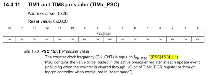
Why do we need to use -1 ?
This is the setup as per the registers in STM32. The Prescaler Register and the ARR Registers are setup in a way, that they add a 1 to the value.
So whatever value we enter for the PSC, 1 will be added to that value. This is why we enter 1 less than the actual value.
THE CODE
Below is the code for the main function.
 int main()
{
  ....
  TIM1->CCR1 = 30;
  HAL_TIM_PWM_Start(&htim1, TIM_CHANNEL_1);
  while (1)
  {}
}- Inside the main function, set the pulse value in the Capture Compare Register (CCR).
- Since I am using Channel 1, the Register is CCR1. similarly, You can CCR2 for channel2, CCR3 for channel3 and so on.
- Finally Start the Timer in PWM mode
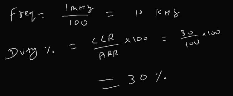
The value set in the CCR decides the width of the pulse. The formula to calculate the duty cycle is shown below
RESULT
Below is the image showing the PWM pulse captured on the Logic Analyser.
The image shows a PWM waveform with the following characteristics:
- Frequency: 10 kHz — each complete cycle lasts 100 microseconds.
- Duty Cycle: 30% — the signal stays HIGH for 30 microseconds and LOW for 70 microseconds in each cycle.
- The waveform clearly displays consistent pulse spacing and width, confirming stable PWM output.
VIDEO TUTORIAL
You can check the video to see the complete explanation and working of this project.
Check out the Video Below
PROJECT DOWNLOAD
Info
You can help with the development by DONATING Below.
To download the project, click the DOWNLOAD button.
🙏 Support Us by Disabling Adblock
We rely on ad revenue to keep Controllerstech free and regularly updated. If you enjoy the content and find it helpful, please consider whitelisting our website in your ad blocker.
We promise to keep ads minimal and non-intrusive.
Thank you for your support! 💙





hello
im usin stm32f407vet6 to control bldc motor for my graduation project
idk whats the teacher sayin about the frequency must be 5kHz he said use only PWM and dont use the adc the sys frequency is 84MHz
can u plz help in configuring the card also help on codin !
This article explains the exact thing, how to generate PWM with some fixed frequency. Please read it, or watch the video.
Para que utilizas interrupciones! solo quiero enviar una señal pwm solo eso. You code while is empty not interrpt
Where did I used interrupt ?
Great example! Worked fine for me for anyone who can’t get it working
1) Make sure PWM Timer is enabled.
2) Make sure CCR value is correct.
3) Double check Timer clock settings.
Thanks for your tutorial.
I switched from Microchip to STM32 and everything is a little bit different^^
I use the Board Nucleo G474RE and got the PWM-Output working. So I wanted to use more outputs with the same PWM-Timer and set the CCR for Channel 2, 3 and 4 of TIM1.
Unfortunately I get only an output on channel 1.
I tried this:
HAL_TIM_PWM_Start(&htim1, TIM_CHANNEL_1 | TIM_CHANNEL_2 | TIM_CHANNEL_3 | TIM_CHANNEL_4);
this:
HAL_TIM_PWM_Start(&htim1, TIM_CHANNEL_1);
HAL_TIM_PWM_Start(&htim1, TIM_CHANNEL_2);
HAL_TIM_PWM_Start(&htim1, TIM_CHANNEL_3);
HAL_TIM_PWM_Start(&htim1, TIM_CHANNEL_4);
and this: //makes no sense for me…
HAL_TIM_PWM_Start(&htim1, TIM_CHANNEL_1 & TIM_CHANNEL_2 & TIM_CHANNEL_3 & TIM_CHANNEL_4);
with the CCR-Settings:
TIM1->CCR1 = 120; // PWM OUTPUT is on PIN A5 (PC0)
TIM1->CCR2 = 120; // PWM OUTPUT is on PIN A4 (PC1)
TIM1->CCR3 = 120; // PWM OUTPUT is on opposite Pin of A5 (PC2)
TIM1->CCR4 = 120; // PWM OUTPUT is on opposite Pin of A4 (PC3)
best regards
Yeah, I got it running.
Unfortunately I selected “Output Compare CHx” instead of “PWM Generation CHx”.
I want to see how you wire up the complete circuit and what are the necessary links
Hi I want to use example but with an interrupt, can I modify CCRx while using interrupt? if not I can just use the example as is. But will I get accurate timing with the cpu running other parts of the code if I don’t use interrupt?
Hi I want to use example but with an interrupt? can I modify CCRx while using interrupt? if not I can just use the example as is. But will I get accurate timing with the cpu running other parts of the code if I don’t use interrupt?
I used the same configuration, but the last example didnt work either. There is no signal output at TIM_CH1. The others worked as expected.
I use STM32F410RB board.
There is nothing in this example, so “not working” is not possible.
Check your CCR value, also if you have started the timer in PWM mode.
Also make sure you are measuring the output from the right pin.
You are the best! Thanks for all of your work.
I am using the STM32F401RE with the same code and same configuration, I confirmed the oscillator is 8Mhz and check that TIM1 is on APB1 – when I connect my logic analyzer I see nothing, no PWM signal.
is there something I can check to figure out what I am missing ?
2 things.
Thanks, I fixed the problem – another question, to bring the frequency to 100 kHz, the ARR to 10 instead of 100 ?
yes
That works like a charm !
I am running a Nucleo-64 with a STM32F401RE on it and the PWM frequency, as clocked by APB1, is nothing compared to what it should be. Say APB1 clock frequency is 84MHz and the pre-scale is 20 I get 19.84MHz on the PWM output?
In the clock setup make sure that input frequency is 8 MHz and not 25 MHz
How to generate a center aligned pwm.
Because the PWM is a periodic signal it is center aligned.
But it is easier to to read the time if you don’t view it as center aligned.