Updated On: June 20, 2026
How to Use STM32 Timers in Gated Mode for Conditional Counting and PWM Control
In Gated Mode, a timer counts only while a specific trigger signal is active. This allows you to control timer operations based on external inputs, like a button press, or internal signals from another timer — without writing extra code to start or stop the timer.
In this tutorial, we’ll explore how to configure STM32 timers in Gated Mode, set up triggers from both external pins and internal timers, and generate PWM outputs that are active only when needed. By the end, you’ll understand how to make your timers smarter and more responsive to real-world signals.
I will use a button for the trigger signal. When the button will be pressed, the trigger signal will go LOW and the counter will start running. The timer will output a PWM signal at this point. When the button is released, the trigger signal will go HIGH, the counter will stop and so does the PWM signal.
We will also see how to automate the process without the need of using the button for the trigger. Basically we will use another timer to generate the trigger signal periodically, and this timer will act as the master timer.
Understanding STM32 Timer Gated Mode
STM32 timers are highly flexible, and Gated Mode is one of the slave timer modes that makes them respond automatically to external or internal signals. Unlike a regular timer that runs continuously, a timer in Gated Mode counts only when a trigger signal is active, allowing precise control of timing and PWM outputs without constantly monitoring inputs in software.
This mode is particularly useful in applications like:
- Generating PWM only when a button is pressed or a sensor is active
- Measuring the duration of an external event
- Synchronizing one timer to another timer’s output
In Gated Mode:
- The timer is configured as a slave.
- A trigger source is selected (external pin or internal timer).
- The timer starts counting when the trigger becomes active (HIGH or LOW, depending on polarity).
- The timer stops counting when the trigger becomes inactive.
- The counter does not reset automatically, so it can accumulate over multiple gate pulses.
Trigger Sources in Gated Mode
The STM32 allows multiple trigger sources for Gated Mode:
- External Trigger (ETR): Any external signal connected to the ETR pin can start or stop the timer.
- Timer Internal Trigger (ITRx): Another timer’s output can be used as the trigger to synchronize multiple timers.
- Filtered Inputs: The timer can also use filtered versions of the trigger signal to avoid glitches.
Polarity and Active Level
The trigger signal can be configured to determine when the timer counts:
- Active HIGH: Timer counts when the trigger is HIGH.
- Active LOW: Timer counts when the trigger is LOW.
This flexibility allows you to adapt the timer behavior to your circuit logic, whether it’s a button, sensor, or PWM signal from another timer.
Practical Use Cases
Some real-world applications of Gated Mode include:
- PWM controlled by a switch: Generate a PWM only when a user presses a button.
- Event duration measurement: Count how long a sensor stays active.
- Multi-timer synchronization: One timer acts as a master, gating multiple slave timers for complex timing sequences.
The image below shows an STM32 timer operating in Gated Mode.
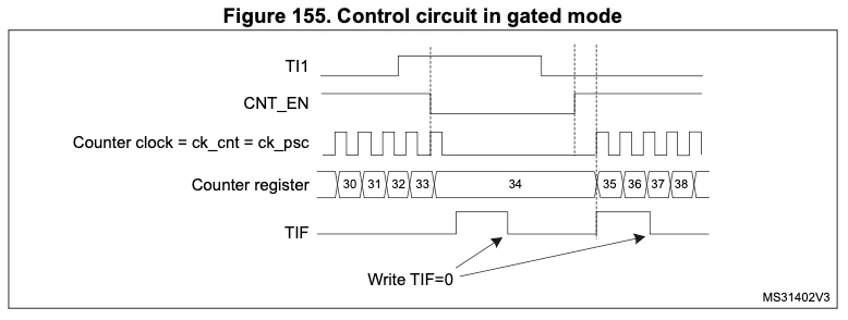
The TI1 line is the trigger input. The timer counts only while TI1 is active (high or low depending on configuration).
- When TI1 goes active, CNT_EN becomes high, enabling the timer clock.
- The Counter Register increments with each timer clock pulse while the gate is active.
- When TI1 becomes inactive, counting pauses automatically.
- The TIF (Timer Interrupt Flag) is set when the timer reaches a compare or overflow event, indicating an update.
Using a button as the trigger
In this example, we’ll use a simple push-button as the trigger for the STM32 timer in Gated Mode. When the button is pressed, the timer starts counting and generates a PWM signal (or other timer outputs) as configured. When the button is released, the timer pauses automatically, without resetting the counter.
CubeMX Configuration
The image below shows the configuration for the TIM1 in the Slave Gated Mode.
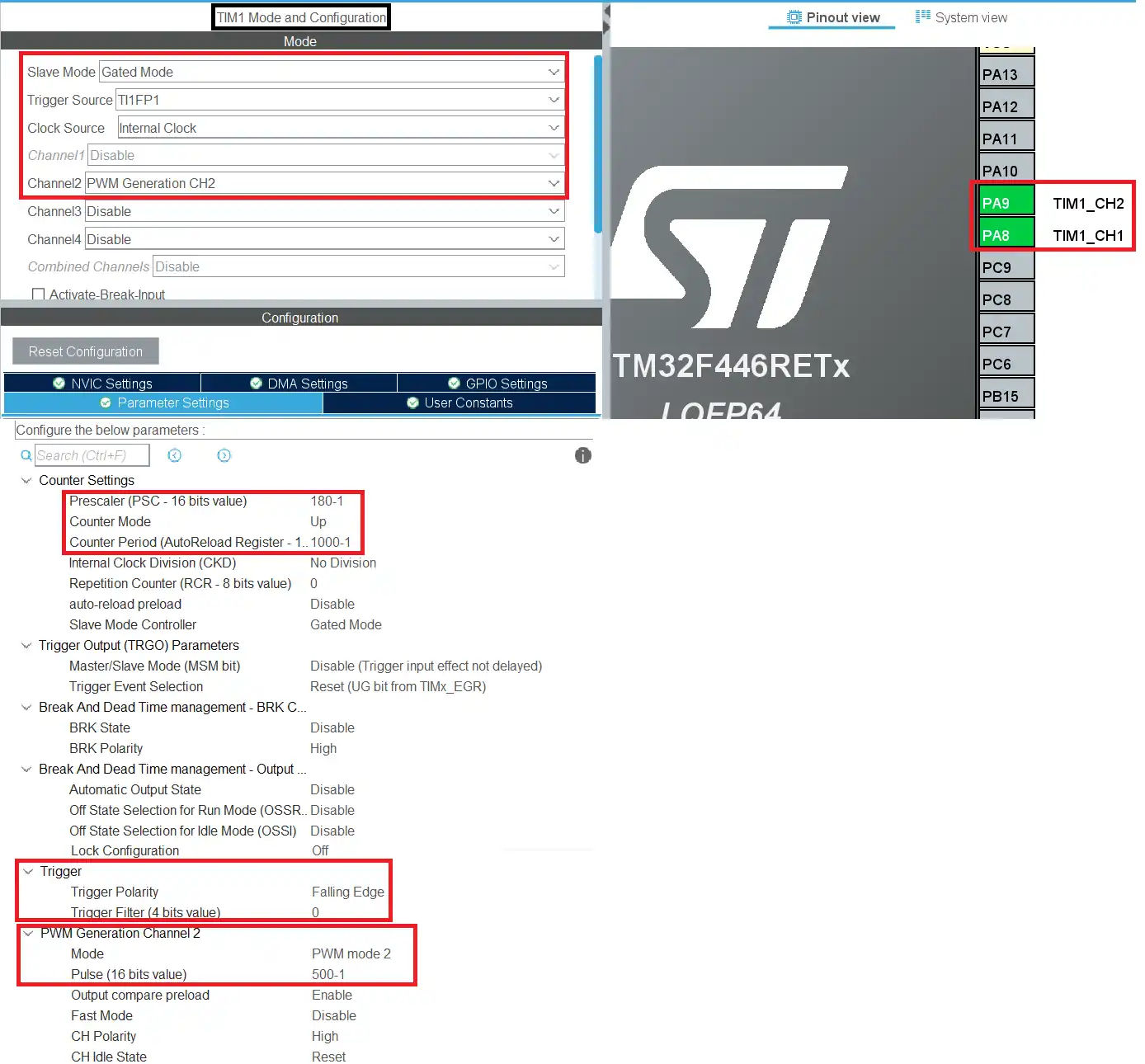
- The Timer is configured in the Gated Mode with Trigger source being selected as the TI1FP1, basically the channel 1.
- The channel 2 is configured to output a PWM signal.
- The pin PA8 is the CH1 pin where we will connect the button to and the pin PA9 is the CH2 pin where the PWM will be generated.
- The TIM1 is connected to APB2 BUS, which is running at 180MHz. So a PSC of 180 along with the ARR value of 1000 will bring down the clock to 1KHz.
- This will be the Frequency of the PWM signal.
- Also the Pulse value is set to 500, which is 50% of the ARR. Thus making the duty cycle 50%.
- The trigger polarity is set to falling edge, therefore the counter will only operate as long as the signal is LOW.
Note:
Calculate the ARR and CCR values for the STM32F4 Timers using the STM32F4 PWM Tool:
https://controllerstech.com/tools/stm32f4-pwm-calculator/
Code for the Gated Mode
There is not much in the code. We will simply start the timer in the PWM mode.
HAL_TIM_PWM_Start(&htim1, TIM_CHANNEL_2);Here I am using the timer 1 channel 2 to generate the PWM signal.
Wiring Diagram
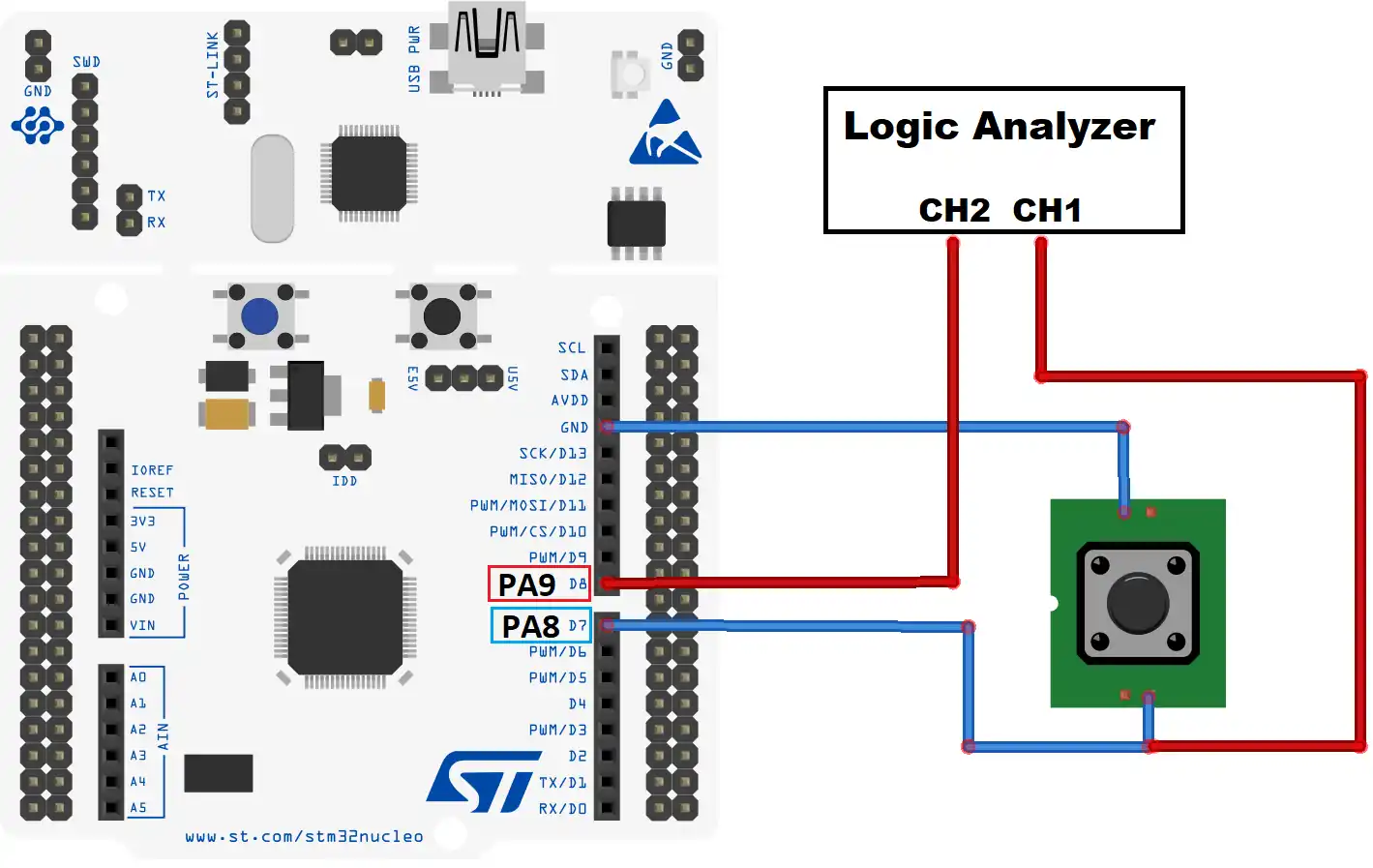
As shown above, the button is connected between the GND and the pin PA8. The pin PA9 is connected to the Logic Analyzer, where we will see the output of both the button and the PWM.
Output
Below is the GIF showing the working.

As you can see above, whenever the trigger signal goes low we can see the PWM being generated.
Basically when the button is pressed, the pin PA8 is pulled to the ground. As soon as this trigger signal goes LOW, the counter resumes and the PWM is generated. And when the button is released, the pin PA8 is pulled back to high, therefore the trigger signal goes HIGH again. The counter stops at this point and since the counter is not running, the PWM signal also stops.
Using an Automatic Trigger Signal
We saw how to use the button as the trigger signal, now we will see how can we automate this process. I am going to use another timer to generate a trigger signal periodically.
Below is the picture from the MCU reference manual showing the Internal Trigger System in the F446RE.
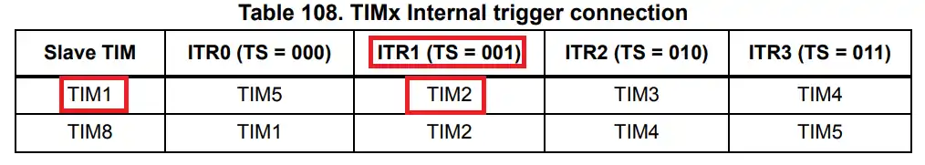
As you can see above, the TIM1 is a slave to TIM2 and can be triggered by the ITR1 signal.
CubeMX Configuration
Below is the configuration for both the TIM1.
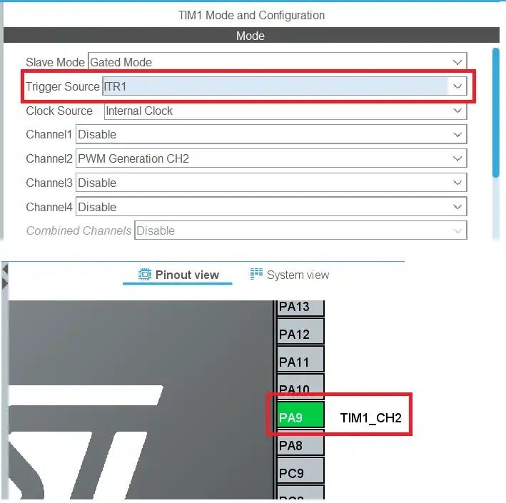
The only change I made here is that the trigger source has been changed to ITR1. Also note that the PA8 has been disabled now since the trigger source is set to internal trigger between the timers.
Below is the configuration for both the TIM2.
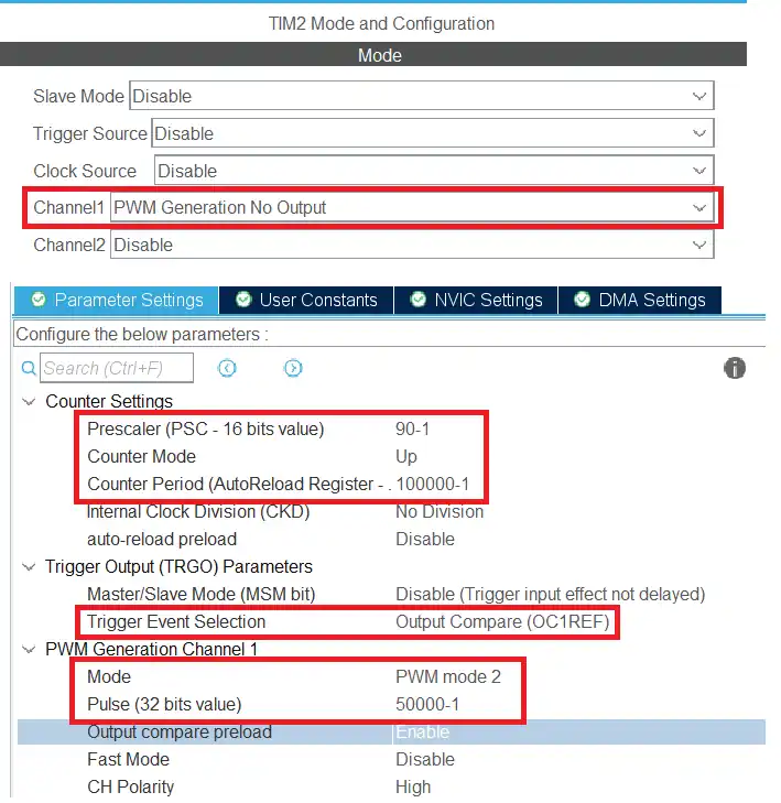
- The TIM2 Channel 1 is configured to generate the PWM with no output. The output will be fed to the internal Trigger signal.
- The TIM2 is connected to APB1 BUS, which is running at 90MHz. So a PSC of 90 along with the ARR value of 100000 will bring down the clock to 10Hz.
- This will be the Frequency of the PWM signal.
- Also the Pulse value is set to 50000, which is 50% of the ARR. Thus making the duty cycle 50%.
- Basically the trigger signal will remain HIGH and LOW for equal amount of time, i.e. 50ms.
- The Trigger Event is set to OC1REF, i.e. the output compare of channel 1.
Code for using automatic trigger
  HAL_TIM_PWM_Start(&htim1, TIM_CHANNEL_2);
HAL_TIM_PWM_Start(&htim2, TIM_CHANNEL_1);Here we will start both the timers in PWM mode. The TIM1 channel 2 is connected to the Logic analyzer and the TIM2 channel 1 will provide the trigger signal.
Output
Image below shows the output of the automatic trigger signal.

As you can see above, the PWM is being generated at fixed intervals.
The signal is disabled for 50ms and PWM is also being generated for 50ms.
The PWM frequency is 1KHz and the duty cycle is 50%.
Video Tutorial
STM32 Timer Gated Mode – Complete Video Tutorial
This video demonstrates how to configure and use STM32 timers in Gated Mode. You’ll learn how to make a timer count only when a trigger signal is active, use both external signals and other timers as triggers, and generate PWM outputs that run conditionally. The step-by-step walkthrough covers CubeMX configuration, HAL implementation, oscilloscope testing, and shows practical examples like button-controlled PWM and timer-to-timer gating.
Watch the VideoConclusion
Gated Mode in STM32 timers allows precise control over when a timer counts by linking it to an external or internal trigger. This makes it ideal for applications where timer outputs, like PWM signals, need to be active only under certain conditions.
Using Gated Mode, you can easily control timers with simple inputs like buttons or with more complex signals from other timers, without writing extra software logic to start or stop the timer manually. This reduces code complexity and improves system reliability.
By following this tutorial, you now know how to configure CubeMX, implement Gated Mode in HAL, and test the setup with real hardware. These concepts open the door to advanced timing applications such as conditional PWM generation, event duration measurement, and synchronized multi-timer operations.
Browse More STM32 Timer Tutorials
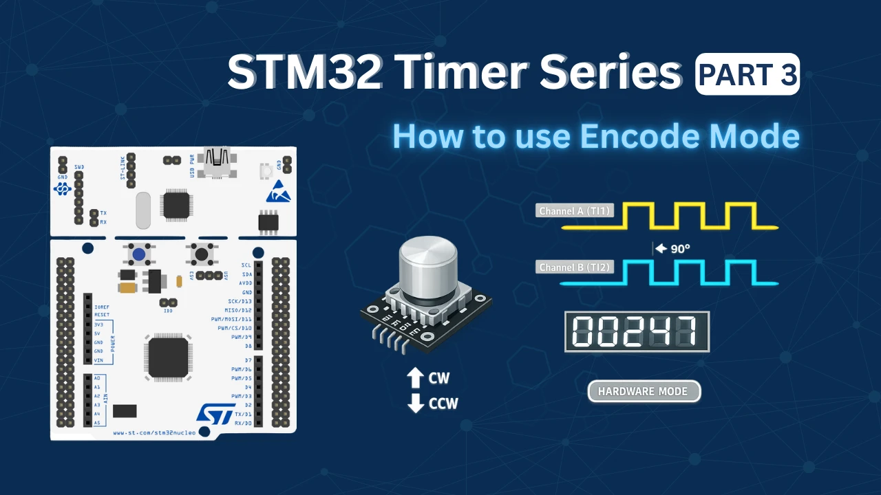
STM32 Timers (Part 3): How to use the Timer Encoder Mode
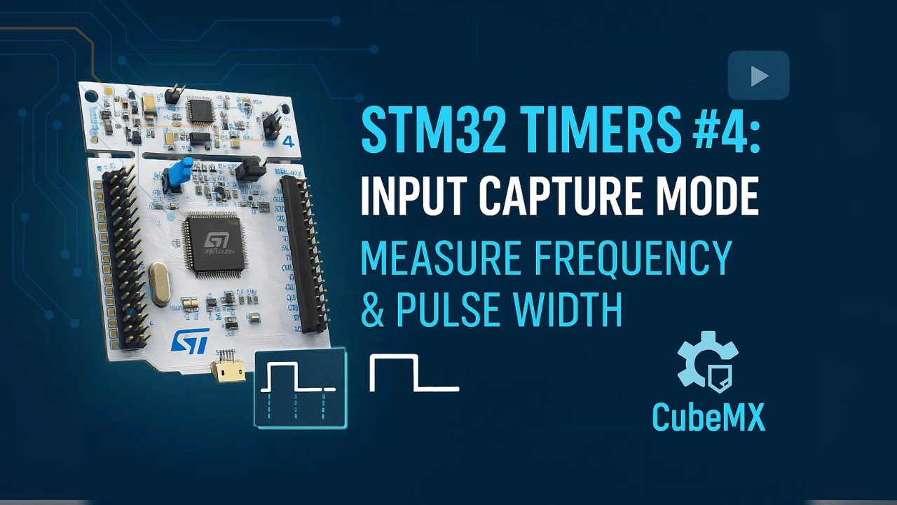
STM32 Input Capture: Measure Frequency & Pulse Width
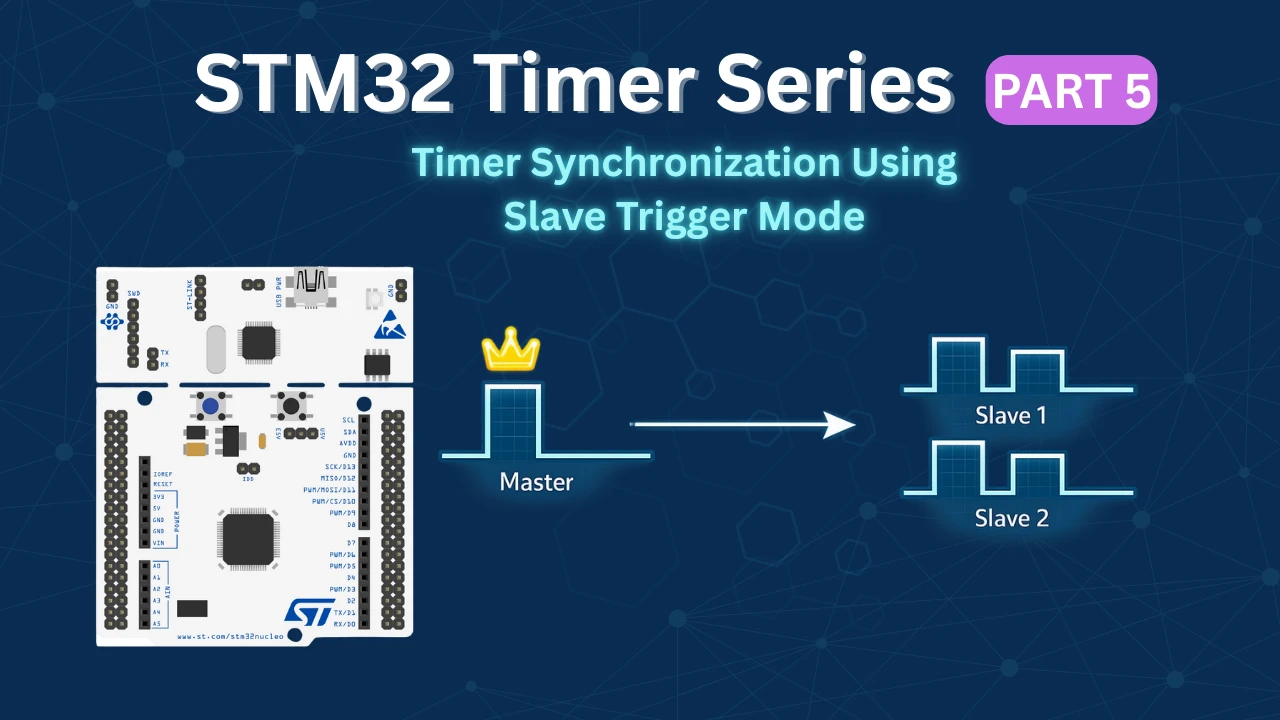
STM32 Timer Synchronization: Slave Trigger Mode with CubeMX & HAL
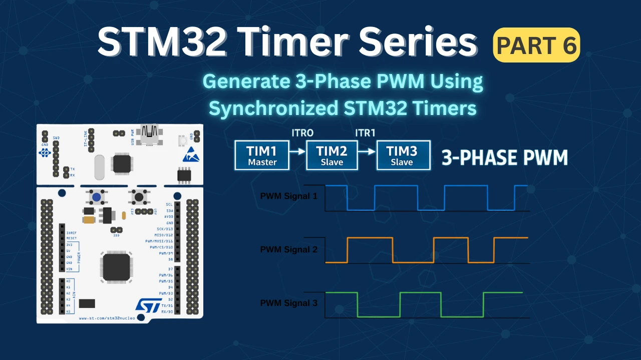
STM32 Timers (Part 6): Timer Synchronization for 3-Phase PWM Generation
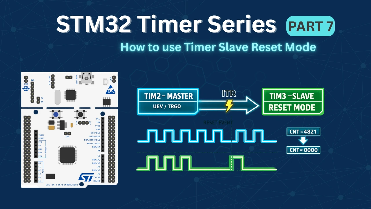
STM32 Timers (Part 7): Timer synchronization using Slave Reset mode
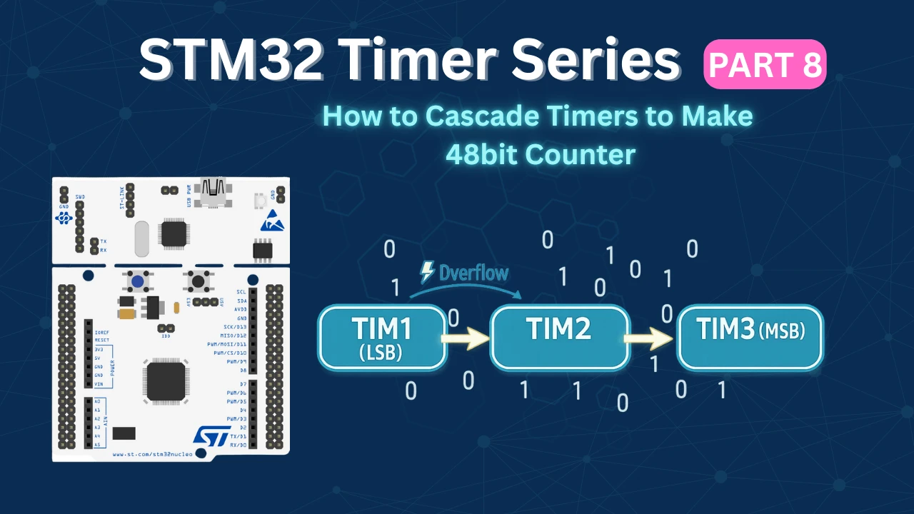
STM32 Timers (Part 8): How to Create a 48-Bit Counter by Cascading Timers
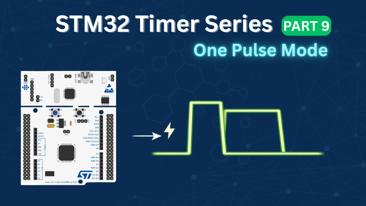
STM32 Timers (Part 9): One Pulse Mode (OPM) – Generate Precise Triggered Pulses with Delay and Width Control
STM32 Slave Gated Mode Project Download
STM32 Slave Gated Mode FAQs

Subscribe
Login
0 Comments
Newest
