Control Stepper motor using Rotary Angle Sensor
I have covered a tutorial Stepper Motor a while back, and today we will see how can we control the positioning of stepper motor using a Rotary angle sensor. If you don’t have this sensor, you can use any potentiometer also.
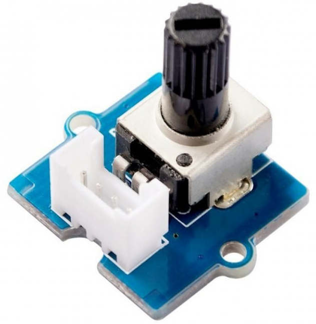
The rotary angle sensor is a type of potentiometer, which produces analog output between 0 and Vcc (3.3V) . The angular range is 300 degrees with a linear change in value. The sensor works with ADC
CubeMX Setup
As i have mentioned above that the sensor works with ADC, so we need to enable the ADC
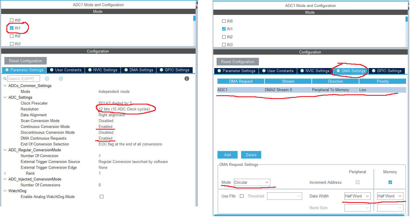
- As you can see above, I have enabled channel 1 of ADC1
- Resolution is selected as 12 bits
- Continuous Conversion is enabled
- DMA request is also enabled, as we will be using DMA in this tutorial
- DMA mode is circular, and the Data width is Half Word (16 bits)
This is all for ADC setup, now we will setup the 4 Pins as output, to control our stepper motor
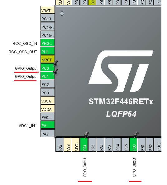
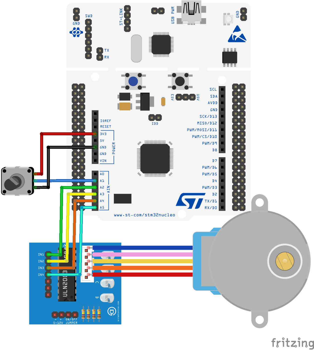
As shown above, I am using Pins PA4, PB0, PC1 and PC0 as the output pins. These Pins will be connected to the stepper Motor IN1, IN2, IN3 and IN4 respectively
We also need to configure a timer to give delays in microseconds. This will be used to control the RPM of the stepper

Here I am using Timer6 for this purpose. I don’t think I need to explain this part, but anyway you can check the explanation Microsecond/Nanosecond delay in STM32
This completes the setup part. The connection between the stepper, Sensor and the microcontroller is shown below
Some Insight into the code
Please go through the basic concepts of stepper motor. I will not cover them here as I have already covered them -> Interface Stepper motor with STM32
First of all we will do some basic defining.
#define IN1Port GPIOA
#define IN1Pin  GPIO_PIN_4

#define IN2Port GPIOB
#define IN2Pin  GPIO_PIN_0

#define IN3Port GPIOC
#define IN3Pin  GPIO_PIN_1

#define IN4Port GPIOC
#define IN4Pin  GPIO_PIN_0

#define stepsperrev 2048


void delay (uint16_t us)
{
	__HAL_TIM_SET_COUNTER(&htim6, 0);
	while (__HAL_TIM_GET_COUNTER(&htim6) < us);
}

void SetPin (GPIO_TypeDef* GPIOx, uint16_t GPIO_Pin)
{
	HAL_GPIO_WritePin(GPIOx, GPIO_Pin, GPIO_PIN_SET);
}

void ResetPin (GPIO_TypeDef* GPIOx, uint16_t GPIO_Pin)
{
	HAL_GPIO_WritePin(GPIOx, GPIO_Pin, GPIO_PIN_RESET);
}- Here First of all we will define the respective pins, that are connected to the Stepper motor
- After defining pins, we need to define the number of steps per revolution. I will be using the wave Drive in this tutorial, so the number of steps are 2048. If you want to use half drive, these number of steps should be 4096
- Then create a function that can produce delay in microseconds
- next create functions to Set and Reset the Pins
Stepper Functions
void stepper_wave_drive (int step)
{
	switch (step){
		case 0:
			  SetPin(IN1Port, IN1Pin);   // IN1 SET
			  ResetPin(IN2Port, IN2Pin);   // IN2 RESET
			  ResetPin(IN3Port, IN3Pin);   // IN3 RESET
			  ResetPin(IN4Port, IN4Pin);   // IN4 RESET
			  break;

		case 1:
			  ResetPin(IN1Port, IN1Pin);   // IN1 RESET
			  SetPin(IN2Port, IN2Pin);   // IN2 SET
			  ResetPin(IN3Port, IN3Pin);   // IN3 RESET
			  ResetPin(IN4Port, IN4Pin);   // IN4 RESET
			  break;

		case 2:
			  ResetPin(IN1Port, IN1Pin);   // IN1 RESET
			  ResetPin(IN2Port, IN2Pin);   // IN2 RESET
			  SetPin(IN3Port, IN3Pin);   // IN3 SET
			  ResetPin(IN4Port, IN4Pin);   // IN4 RESET
			  break;

		case 3:
			  ResetPin(IN1Port, IN1Pin);   // IN1 RESET
			  ResetPin(IN2Port, IN2Pin);   // IN2 RESET
			  ResetPin(IN3Port, IN3Pin);   // IN3 RESET
			  SetPin(IN4Port, IN4Pin);   // IN4 SET

		}
}

void stepper_set_rpm (int rpm)  // Set rpm--> max 13, min 1,,,  went to 14 rev/min
{
	delay(60000000/stepsperrev/rpm);
}

void stepper_step_angle (int angle, int direction, int rpm)
{
	float anglepersequence = 0.703125;  // 360 = 512 sequences
	int numberofsequences = (int) (angle/anglepersequence);

	for (int seq=0; seq<numberofsequences; seq++)
	{
		if (direction == 0)  // for clockwise
		{
			for (int step=3; step>=0; step--)
			{
				stepper_wave_drive(step);
				stepper_set_rpm(rpm);
			}

		}

		else if (direction == 1)  // for anti-clockwise
		{
			for (int step=0; step<4; step++)
			{
				stepper_wave_drive(step);
				stepper_set_rpm(rpm);
			}
		}
	}
}- Stepper_wave_drive will drive the motor for the required number of steps. In wave Drive, motor takes 2048 steps to complete 1 revolution, so we have to call it many times depending on the angle of rotation.
- then we have a function to set the RPM for the motor. This basically works like a delay between 2 stpes.
- stepper_step_angle will make the motor step by the given angle. You can also control the Direction of rotation (1->CCK, 0->CK), and the RPM of the motor
void Stepper_rotate (int angle, int rpm)
{
	int changeinangle = 0;
	changeinangle = angle-currentAngle;
	if (changeinangle > 1)
	{
		stepper_step_angle (changeinangle,0,rpm);
		currentAngle = angle;
	}
	else if (changeinangle <-1)
	{
		changeinangle = -(changeinangle);
		stepper_step_angle (changeinangle,1,rpm);
		currentAngle = angle;
	}

}
This is a relatively new function and isn’t present in the stepper motor tutorial.
- Stepper_rotate is the function to rotate the motor
- here we will first calculate the change in angle.
- If this change is positive, the motor will rotate in the CK direction by the “change” amount
- if the change is negative, the motor will rotate in the CCK direction
- If the change is less than 1, the motor will not rotate. This is to compensate the fluctuation in the ADC reading
ADC Callback
void HAL_ADC_ConvCpltCallback(ADC_HandleTypeDef* hadc)
{
	voltage = (float)(ADC_VAL*3.3)/4095;
	angle = voltage*300/3.3;
	Stepper_rotate(angle, 10);
}- This is a callback function and will be called when the ADC will finish the conversion
- Here we will first calculate the voltage using the ADC value. This voltage will correspond to the angle sensor has been rotated.
- using this voltage, we will calculate the angle
- and finally feed the angle to the motor
Main function
In the main function, we will just start the timer, and ADC with the DMA
  HAL_TIM_Base_Start(&htim6);  // for us delay
  HAL_ADC_Start_DMA(&hadc1, &ADC_VAL, 1);
Result