Last Updated: March 23, 2026
How to Display Clock on TM1637
This is PART2 of the mini tutorial series covering the 7 segment display using TM1637 driver with STM32. In the previous tutorial we saw how to connect the device with the STM32F103, how to configure the cubeMX and how to display numbers or letters on the 7 segment display.
In today’s tutorial we will write a function to display the number directly without knowing the segment data for the same. We will also use the inbuilt RTC of the STM32 to store the time, which we will fetch and display on the device.
VIDEO TUTORIAL
You can check the video to see the complete explanation and working of this project.
Prerequisite
You must go though the PART1 of this series. I have covered all the basics that you need to know and I am not going to cover them in this tutorial.
Since the topic on the inbuilt RTC is already covered, I advise you to go through it also. Although I will cover a little bit of the RTC in this tutorial, but it is good to have a deeper knowledge on the topic.
Function to Write the Number
We will first see the function to directly display the number on the device. In the previous tutorial we wrote a function to display the data on the device, void TM1637_WriteData (uint8_t Addr, uint8_t *data, int size). The parameter of this function is the segment data for the character you want to display.
The array containing the segment data is defined in the beginning of the source file.
//      A
//     ---
//  F |   | B
//     -G-
//  E |   | C
//     ---
//      D
const uint8_t segmentMap[] = {
 // XGFEDCBA
  0b00111111,    // 0
  0b00000110,    // 1
  0b01011011,    // 2
  0b01001111,    // 3
  0b01100110,    // 4
  0b01101101,    // 5
  0b01111101,    // 6
  0b00000111,    // 7
  0b01111111,    // 8
  0b01101111,    // 9
};This array only contain the data for the equivalent numbers, but if you want you can create a larger array to store the data for the characters as well. This application does not require the use of characters, so we will not focus on that.
Today we will write a function which can take the number as the parameter so that we do not have to worry about the segment data. We will also write the function in such a way that it can handle 1 to 4 digit number itself.
void TM1637_WriteNum (uint8_t Addr, int num, int colon)
{
	uint8_t buffer[4];
int len;The function parameter are as follows
- @Addr is the digit address where you want to display the number.
- @num is the number itself. It can vary between 1 to 4 digits.
- @colon can be either a 0 or 1. It decides whether you want to turn the colon in the middle ON or OFF.
Inside the function we will first define a buffer of 4 bytes. We need to store the relevant segment data for every digit and each digit occupies 1 byte of data. The variable len will store the number of digits the parameter num has. We need to calculate the number of digits in the parameter num, so we will do it as follows.
	if ((num/1000) != 0) len =4;
	else if ((num/100) != 0) len =3;
	else if ((num/10) != 0) len =2;
else len =1;Here we will first divide the num by 1000. If there is some quotient, it would mean that the num has 4 digits in total. For eg- if num = 2345, num/1000 = 2.
If the first condition does not satisfy, we will divide the num by 100. If there is some quotient, it would mean that the num has 3 digits in total. For eg- if num = 345, num/1000 = 0 and num/100 = 3.
We will perform the similar operations to find the length of the parameter num. Once the length is calculated we will store the segment data for the equivalent number.
	for (int i=0; i<len; i++)
	{
		buffer[len-1-i] = segmentMap[num%10];
		num = num/10;
}Here we will first extract the digit at the unit place of the parameter num (num%10) and then store the equivalent segment data for that number starting from the end of the buffer (buffer[len-1-i]).
- For eg- if the num = 2345, num%10 = 5. The segment data for this 5 will be stored in the buffer[3].
- We will start storing the data from the end of the buffer. This is to make sure that the unit place will display on the last digit of the device.
- Then the num variable is divided by 10, which will eliminate the unit place from the variable. For eg- if num = 2345, num/10 = 234.
- This loop repeats an many times as the length of the number.
Next we will control the colon on the display.
if (colon) buffer[1] |= 1<<7; // turn on the colonHere we will check if the colon variable in the parameter is set to 1. If it is, then we need to display the colon on the device. To do this, write a 1 to the most significant bit to the data stored at the buffer[1] position.
Finally we will send the data to the device.
	TM1637_WriteData(Addr, buffer, len);
}We will call the function TM1637_WriteData to send the segment data stored in the buffer array to the device. This function takes the segment data as the parameter, and since we have the segment data for the respective number in the buffer array, we will pass the array to the function.
The main function is as follows.
int main ()
{
  ....
  ....
  TM1637_WriteNum(0xC0, 5678, 0);
  while (1)
  {   }
} Here we will call the function TM1637_WriteNum to directly write the number 5678 to the address 0xC0. We can use this function to send any number between 1 digit to 4 digit.
Below is the image showing the output of the above code.
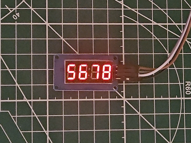
As you can see the number is being displayed on the device.
Display the Clock
As I mentioned earlier, we will use the internal RTC of STM32 to keep record of the current time. Then we will fetch the time and display it on the device.
CubeMX Configuration
Below is the image showing the Clock configuration.
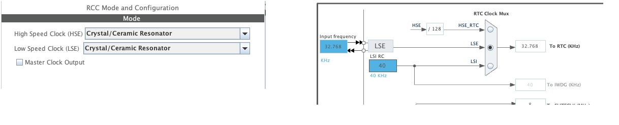
Here I have enabled the Low Speed External (LSE) crystal to provide the 32.768KHz clock to the RTC. The LSE crystal is available on the bluepill board, but if you do not have a separate crystal for the RTC, you can still use the Internal Oscillator of 40KHz.
Next is the configuration of the RTC.
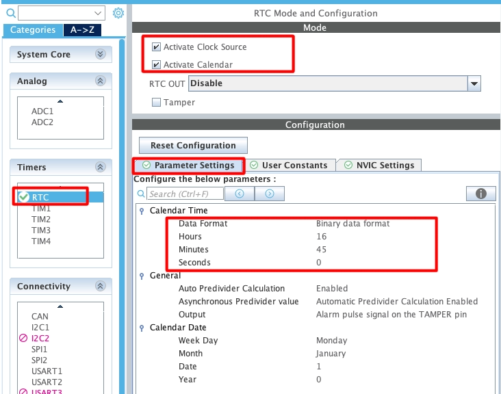
- Activate the clock source as well as the Calendar. Although we are not using the Calendar, but still we need to activate it in order to set the time.
- In the parameter settings, set the current time. Since the Data Format is set to Binary Data Format, you can simply pass the integral values here.
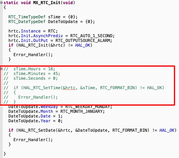
After generating the code, navigate to the RTC Initialisation function and comment out the part where the time is being set. This is to make sure that the time does not reset when the MCU resets.
Set and Get Time
We will write separate functions to set and get the time from the RTC. Let’s start with the set Time function.
void setTime (uint8_t hr, uint8_t min, uint8_t sec)
{
	RTC_TimeTypeDef sTime = {0};

	sTime.Hours = hr;
	sTime.Minutes = min;
	sTime.Seconds = sec;

	if (HAL_RTC_SetTime(&hrtc, &sTime, RTC_FORMAT_BIN) != HAL_OK)
	{
		Error_Handler();
	}

	HAL_RTCEx_BKUPWrite(&hrtc, RTC_BKP_DR1, 0x4567);
}The parameters of this function are the time data that we want to set. We can simply pass the integral values to these parameters.
Inside the function, we will first define the RTC_Time structure. Then store the time data in this structure and pass it to the parameter of the function HAL_RTC_SetTime. Note here that we are using the Binary format for setting the time and hence the integral values work just fine.
After setting the time, write a random value to the backup register. We will use this backup register in the main function later.
Below is the function to get the time from the RTC.
void getTime (uint8_t *Time)
{
	RTC_TimeTypeDef gTime = {0};

	if (HAL_RTC_GetTime(&hrtc, &gTime, RTC_FORMAT_BIN) != HAL_OK)
	{
		Error_Handler();
	}

	Time[0] = (gTime.Seconds)%10;
	Time[1] = (gTime.Seconds)/10;
	Time[2] = (gTime.Minutes)%10;
	Time[3] = (gTime.Minutes)/10;
	Time[4] = (gTime.Hours)%10;
	Time[5] = (gTime.Hours)/10;
}The parameter of this function is the pointer to the array, where the current time will be stored separately in 6 different bytes.
Inside this function, we will first define the RTC_Time structure. Then call the function HAL_RTC_GetTime to fetch the current time from the RTC and store it in the gTime structure we just defined. Note that the time stored is in the binary format.
Now we have the time but we will store each digit separately, so that it will be easier to display this on the TM1637. We will simply separate each digit of the time and store them in the Time array. The seconds data is stored first, then the minutes and at last the hours.
Display Time
We will write a separate function to display the time on the TM1637.
void TM1637_WriteTime (uint8_t *Time, int colon)
{
	static int dColon = 0;
	static int sChange = 0;
uint8_t buffer[4];The parameter of this function are
- @Time is the pointer to the time array where the time data is stored in the separate bytes.
- @colon can be either a 0 or 1. It decides whether you want to blink the colon in the middle.
We will define the static variable dColon to toggle the state of the colon and sChange will be used to keep track of the last value stored in the unit place of the Time array. You will understand them below.
	for (int i=0; i<4; i++)
	{
		buffer[3-i] = segmentMap[Time[i]];
}Here we will first check the value of the element of the Time array and then store the relevant segment data in the buffer array. Again the data is stored backwards, so to make sure that the unit place will display on the last digit of the device.
	if (sChange != Time[0])  // if the unit digit in the time changes
	{
		if (colon) dColon = !dColon;
		if (dColon) buffer[1] |= 1<<7;
		sChange = Time[0];  // update the sChange with current value of the unit digit
		TM1637_WriteData(0xC0, buffer, 4);
	}
}As we don’t know how often this function will be called, we will prevent it from sending the same data to the device. For eg- if the function is called every 100ms, it will send the same time (specifically seconds) 10 times. To prevent this and also to manage the blinking of the colon more efficiently, we will use the static variable sChange.
We will first compare if the new value in the unit digit of the Time array is different from what it was last time. If the time data contains minutes and seconds, this unit digit will change every second and if the time data contains hours and minutes, this will change every minute.
If the value is different, we will check if the colon blinking (parameter colon) is enabled. If it is, then change the state of the static variable dColon. This will simply switch it from 0 to 1 or vice versa. Now if the value of the dColon is 1, that means we need to turn on the colon on the display, so write a 1 to the most significant bit of the buffer[1].
Then update the sChange variable with the current value at the unit place of the Time array. Finally send the buffer to the device, starting from the address 0xC0.
The main function
In the main function we will first set the current time to the RTC.
int main ()
{
  ....
  ....
  if (HAL_RTCEx_BKUPRead(&hrtc, RTC_BKP_DR1) != 0x4567)
  {
	  setTime(16, 54, 0);
}In the main function we will first check the value stored in the backup Register. If the set time function is already called once, the value must be 0x4567. Otherwise we will call the set time function to set the current time to the RTC.
This backup register is used as a protection to prevent the set time function from being called each time the device resets.
  while (1)
  {
	  getTime(currentTime);
	  TM1637_WriteTime(¤tTime[2], 1);  // Hours : Minutes
          TM1637_WriteTime(¤tTime, 1);  // Minutes : Seconds

	  HAL_Delay(200);
  }
}
Inside the while loop we will call the function getTime to fetch the current time from the RTC and store the separated data in the currentTime array. The data stored in the currentTime array is such that the seconds is stored first, followed by the minutes and then hours.
Since the TM1637 display I am using only has 4 digits in total, I can not display the entire clock on it.
Depending on what you want to display on the device, you can send a limited part of the array.
For eg- If you want to display minutes and seconds, send the array currentTime. Although we are passing the entire 6 bytes array here, but since the buffer defined in theWriteTime function can only store 4 bytes, it will store the first 4 byes of the currentTime array. This includes minutes and seconds.
Similarly, If you want to display Hours and Minutes, send the array currentTime[2]. The minutes data inside this array starts from the position 2, so we are passing the 4 bytes of minutes and hours data.
Result
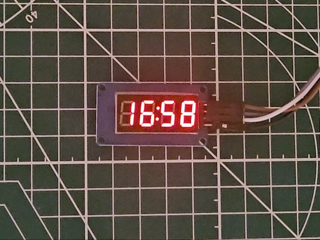
Below is the gif showing the clock with minutes and seconds data.

Note that even the while loop is repeating every 200ms (According to the code), the clock and the colon is working perfectly fine.
Below is the image showing the clock with Hours and Minutes data.