Interface MPU6050 (GY-521) with STM32
I have already covered How to get acceleration values in ADXL345. MPU6050 is also an accelerometer cum Gyroscope device and today in this tutorial we are going to interface it with the STM32 microcontroller.
I will use LCD 20×4 to display the respective values. What’s interesting here is that the LCD and GY521, both will be connected to the same I2C peripheral. So we are only using 2 wires from microcontroller to interface both the devices and that’s what the true purpose of I2C is.
MPU6050 Have a lot of functions and its not possible to cover all of them in just one tutorial. So in part 1, we will only cover the following:-
- How to Initialize the device
- How to read RAW values
- How to convert acceleration values in ‘g’
- and Gyroscope values in dps (°/s)
VIDEO TUTORIAL
You can check the video to see the complete explanation and working of this project.
Configuration and Connection
Below is the image showing the cubeMX configuration for the I2C.
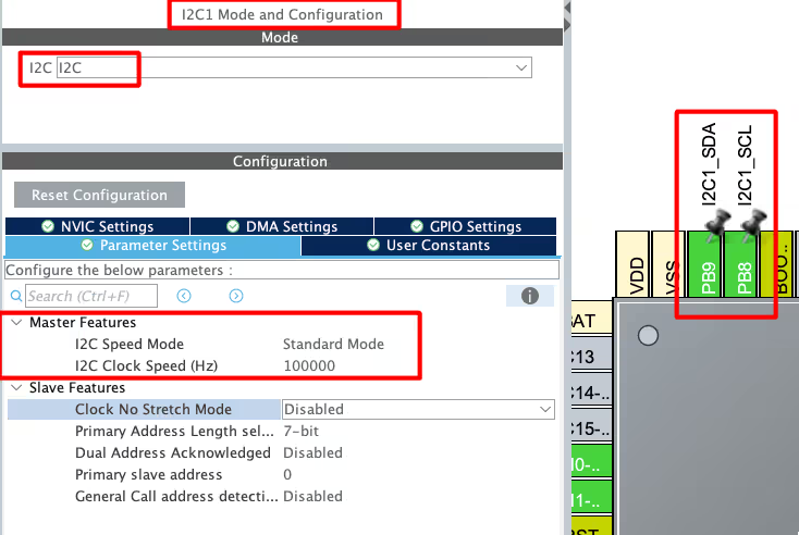
I have enabled I2C1 in the standard mode with the clock speed of 100KHz. The pins PB8 and PB9 are configured as SCL and SDA respectively.
Below is the image showing the connection between the MPU6050, LCD20x4 and the Nucleo F446.
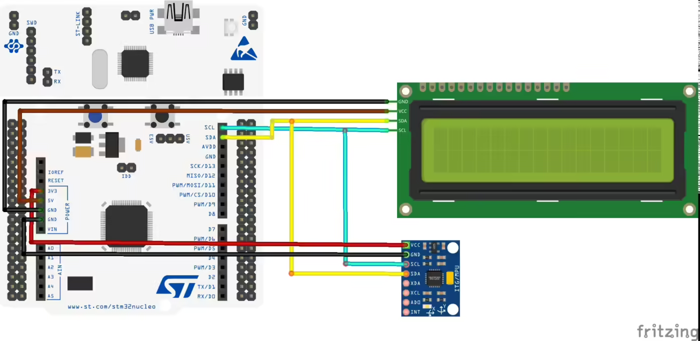
As you can see in the image above, both MPU6050 and the LCD20x4 are connected to the same I2C pins. The MPU6050 is powered with 3.3V and the LCD20x4 is powered with 5V from the nucleo board itself.
The Slave Address of the MPU6050
Below is the image from pg 33 of the MPU6050 datasheet.
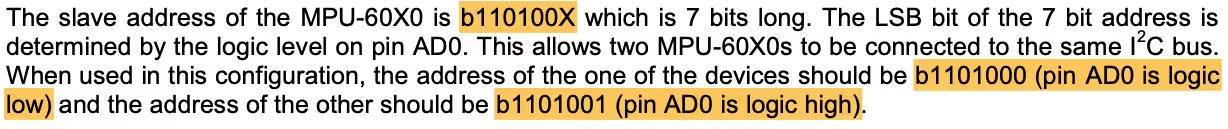
The 7 bit address is b110100X. Here the value of X depends on the pin AD0. This pin is available on the breakout board of the sensor and since we have left it not-connected, this pin can be treated as Logic LOW. This means that the 7bit Slave Address of the device is 0x68. But we need to provide the 8bit address for the STM32 HAL, therefore we will shift this 7 bit address to the left by 1 place, 0x68<<1 = 0xD0.
Some Insight into the CODE
Initialisation
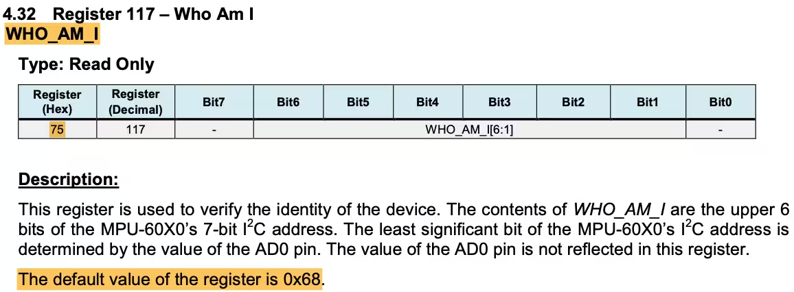
In order to initialise the sensor, we will first check if the sensor is responding by reading the “WHO_AM_I (0x75)” Register. If the sensor responds with 0x68, that would means it’s available and good to go.
void MPU6050_Init (void)
{
  uint8_t check;
  uint8_t Data;

  HAL_I2C_Mem_Read (&hi2c1, MPU6050_ADDR, 0x75, 1, &check, 1, 1000);  // read WHO_AM_I
  if (check == 0x68)  // 0x68 will be returned by the sensor if everything goes well
{Here we will use the function HAL_I2C_Mem_Read to directly read from the given memory register (0x75). If the sensor respond with the value 0x68, we can proceed with the rest of the initialisation.
Then we will configure the “PWR_MGMT_1 (0x6B)” Register. Below is the image of the register.
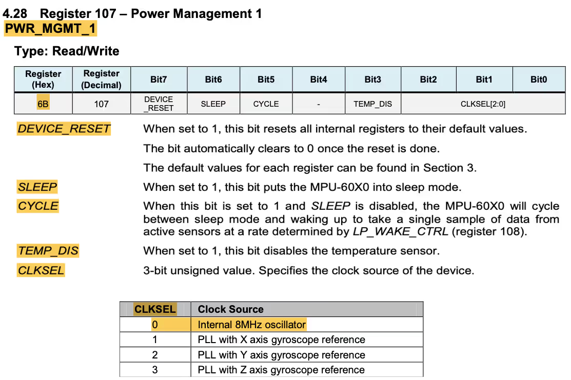
	// power management register 0X6B we should write all 0's to wake the sensor up
	Data = 0;
HAL_I2C_Mem_Write(&hi2c1, MPU6050_ADDR, 0x6B, 1, &Data, 1, 1000);We will reset this register to 0. In doing so, we will :
- Select the internal clock source of 8 MHz.
- The Temperature sensor will be enabled.
- The CYCLE between sleep mode and wakeup will be enabled.
- The SLEEP mode will be disabled.
- Also we are not performing the RESET.
Next we have to set the Data output Rate or Sample Rate. This can be done by writing into “SMPLRT_DIV (0x19)” Register. This register specifies the divider from the gyroscope output rate used to generate the Sample Rate for the MPU6050.
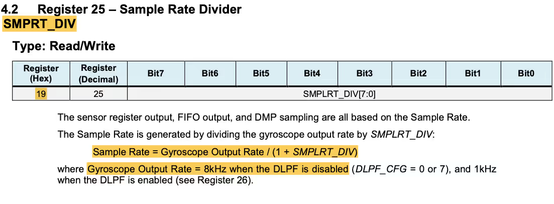
As the formula says Sample Rate = Gyroscope Output Rate / (1 + SMPLRT_DIV). We will keep the DLPF disabled, so the Gyroscope Output Rate will remain 8KHz. To get the sample rate of 1KHz, we will set the SMPLRT_DIV value to 7.
     // Set DATA RATE of 1KHz by writing SMPLRT_DIV register
     Data = 0x07;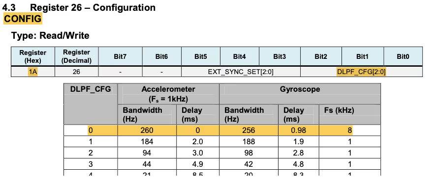
HAL_I2C_Mem_Write(&hi2c1, MPU6050_ADDR, 0x19, 1, &Data, 1, 1000);The “CONFIG (0x1A)” Register can be used to configure the DLPF. Since this register is reset to 0 by default, the DLPF is disabled and the gyroscope output rate is set to 8KHz.
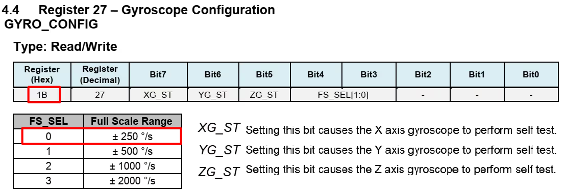
Now we will configure the Accelerometer and Gyroscope registers by modifying the “GYRO_CONFIG (0x1B)” and “ACCEL_CONFIG (0x1C)”Registers.
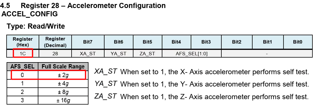
	// Set accelerometer configuration in ACCEL_CONFIG Register
	Data = 0x00;  // XA_ST=0,YA_ST=0,ZA_ST=0, FS_SEL=0 -> <strong>±</strong> 2g
	HAL_I2C_Mem_Write(&hi2c1, MPU6050_ADDR, ACCEL_CONFIG_REG, 1, &Data, 1, 1000);

	// Set Gyroscopic configuration in GYRO_CONFIG Register
	Data = 0x00;  // XG_ST=0,YG_ST=0,ZG_ST=0, FS_SEL=0 -> <strong>±</strong> 250 ̐/s
	HAL_I2C_Mem_Write(&hi2c1, MPU6050_ADDR, GYRO_CONFIG_REG, 1, &Data, 1, 1000);
  }
}Writing (0x00) to both of these registers would set the Full scale range of ± 2g in ACCEL_CONFIG Register and a Full scale range of ± 250 °/s in GYRO_CONFIG Register along with Self-test disabled.
Read Values from MPU6050
We will see How to Read the Data from the sensor and how to convert it in the respective formats. Let us start with the Acceleration values first.
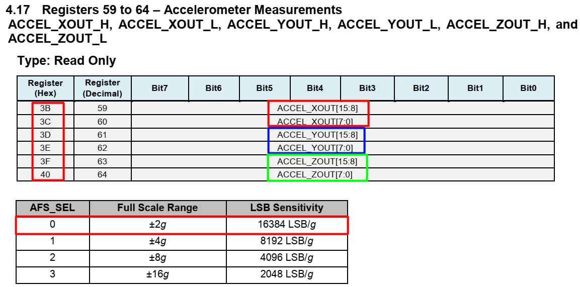
We can read 1 BYTE from each Register separately or just read all 6 BYTES in a burst, all together starting from ACCEL_XOUT_H(0x3B) Register.
void MPU6050_Read_Accel (void)
{
	uint8_t Rec_Data[6];

	// Read 6 BYTES of data starting from ACCEL_XOUT_H (0x3B) register
HAL_I2C_Mem_Read (&hi2c1, MPU6050_ADDR, 0x3B, 1, Rec_Data, 6, 1000);Here we are reading 6 bytes of data, starting from 0x3B register. These values will be stored in the Rec_Data buffer.
The ACCEL_XOUT_H (0x3B) Register stores the higher Byte for the acceleration data along X-Axis and Lower Byte is stored in ACCEL_XOUT_L Register. So we need to combine these 2 BYTES into a 16 bit integer value. Below is the process to do that:-
ACCEL_X = (ACCEL_XOUT_H <<8) | ACCEL_XOUT_L
We are shifting the higher 8 bits to the left and than adding the result with the lower 8 bits.
Similarly we can do the same for the ACCEL_YOUT and ACCEL_ZOUT Registers.
	Accel_X_RAW = (int16_t)(Rec_Data[0] << 8 | Rec_Data [1]);
	Accel_Y_RAW = (int16_t)(Rec_Data[2] << 8 | Rec_Data [3]);
Accel_Z_RAW = (int16_t)(Rec_Data[4] << 8 | Rec_Data [5]);These values will still be the RAW values and we still need to convert them into proper ‘g’ format. You can see in the picture above that for the Full-Scale range of ± 2g, the sensitivity is 16384 LSB/g. So to get the ‘g‘ value, we need to divide the RAW from 16384.
	Ax = (float)Accel_X_RAW/16384.0;
	Ay = (float)Accel_Y_RAW/16384.0;
	Az = (float)Accel_Z_RAW/16384.0;
}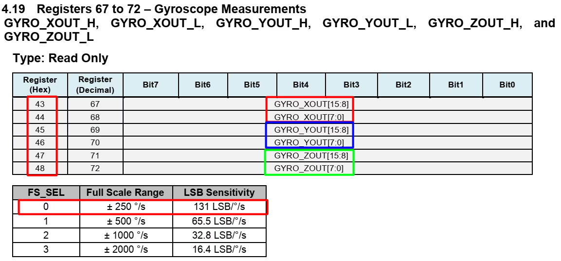
Reading Gyro Data is similar to the that of reading the Acceleration data. We will start reading 6 BYTES of data starting from the GYRO_XOUT_H(0x43) Register. Then Combine the 2 Bytes to get 16 bit integer RAW values.
void MPU6050_Read_Gyro (void)
{
	uint8_t Rec_Data[6];

	// Read 6 BYTES of data starting from GYRO_XOUT_H register
	HAL_I2C_Mem_Read (&hi2c1, MPU6050_ADDR, 0x43, 1, Rec_Data, 6, 1000);

	Gyro_X_RAW = (int16_t)(Rec_Data[0] << 8 | Rec_Data [1]);
	Gyro_Y_RAW = (int16_t)(Rec_Data[2] << 8 | Rec_Data [3]);
	Gyro_Z_RAW = (int16_t)(Rec_Data[4] << 8 | Rec_Data [5]);

	Gx = (float)Gyro_X_RAW/131.0;
	Gy = (float)Gyro_Y_RAW/131.0;
	Gz = (float)Gyro_Z_RAW/131.0;
}As we have selected the Full-Scale range of ± 250 °/s, for which the sensitivity is 131 LSB /°/s, we have to divide the RAW values by 131.0 to get the values in dps ( °/s ).
The main function
Inside the main function we will initialise the LCD, along with the MPU6050.
int main ()
{
  ....
  lcd_init();
  MPU6050_Init();
  lcd_send_cmd (0x80|0x5A);
lcd_send_string ("MPU6050");Then read the accelerometer and gyroscope values in a while loop and display them on the LCD.
  while (1)
  {
    char buf[20];

    // read the Accelerometer and Gyro values
    MPU6050_Read_Accel();
    MPU6050_Read_Gyro();

    // print the Acceleration and Gyro values on the LCD 20x4
    lcd_send_cmd (0x80|0x00);  // goto 1,1
    sprintf (buf, "Ax=%.2fg ", Ax);
    lcd_send_string (buf);

    lcd_send_cmd (0x80|0x40);  // goto 2,1
    sprintf (buf, "Ay=%.2fg ", Ay);
    lcd_send_string (buf);

    lcd_send_cmd (0x80|0x14);  // goto 3,1
    sprintf (buf, "Az=%.2fg ", Az);
    lcd_send_string (buf);

    lcd_send_cmd (0x80|0x0A);  // goto 1,11
    sprintf (buf, "Gx=%.2f", Gx);
    lcd_send_string (buf);

    lcd_send_cmd (0x80|0x4A);  // goto 2,11
    sprintf (buf, "Gy=%.2f", Gy);
    lcd_send_string (buf);

    lcd_send_cmd (0x80|0x1E);  // goto 3,11
    sprintf (buf, "Gz=%.2f", Gz);
    lcd_send_string (buf);

    HAL_Delay (250);  // wait for a while
  }
}We will use the function sprintf to covert the float values to the character format and store them in a buffer. Then send the buffer to the respective locations on the LCD.
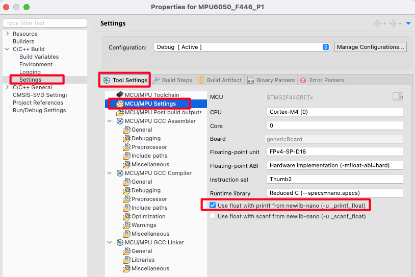
We also need to enable the -u_printf Flag to enable the conversion of float variables.
Goto project->setting->c/c++ build->setting->tool setting->MCU/MPU Settings and enable the -u _printf_float.
Result

As you can see in the image above, the acceleration and gyroscope values are being shown at their respective places. Check out the video below to see the complete working of the sensor.


Thank you for your hard working and well explained, i just want to use this code for my project and monitoring its using Putty. how i can use it can you guide me
Instead of sending the string to LCD (lcd_send_string), send it to putty via the UART.
Thank you, you help me a lot
Hello sir
I have a little difficulty using I2C with DMA to
read values from MPU6050. When using DMA (HAL_I2C_Mem_Read_DMA circular mode), the read value is correct only once and crashes. However, when using I2C in polling mode, the reading value returns to normal.
Try without the circular mode in DMA.
I2C_Read (Address+0x01, buffer, size);
why Address add by 0x01? Please help me
The slave address is 7 bit in size, and the lsb is R/W bit. For the write operation, the R/W bit is a 0, and for read operation this bit is a 1.
For example, assume that the 7 bit slave address is 0x27. For write operation, the slave address will be (0x27<<1)+0 and for read operation the address will be (0x27<<1)+1. The HAL library do this addition automatically.
Oh thank, and we can Read Value with DMA right? I see I2C1_RX DMA in STM32CubeIDE config
at rest it should probably show a naught acceleration or at least near to that. I get 1.01g in Az. Isn’t it weird?
because the earth is pulling you down with 1.0g (9.81 m/s2)
is it a mandatory to use a very high frequency in HCLK? I’m using 32MHz and it doesn’t even read back the WHO_AM_I_REG address. I’m using stm32wb55
problem solved. The answer is not.
Hello, I’ve been wondering about this line
#define MPU9250_ADDR 0XD0
Can you explain what is 0xD0 and where it comes from? I’ve read the article and watch the video but I can’t find any explanation about it.
LSB using for read/write first byte of packece in I2C protocol. 1byte -> a6 a5 a4 a3 a2 a1 a0 r/w. So xD0 =11010000 in binary equal, if you slide right one bit this value be 1101000 in binary and equal x68 in hex.
Hi,
The address of the device is 0x68.
But this is needed to be shifted to the left by 1 to allow bit 0 to be set as 0/1 for R/W when communicating with device.
So,
(0x68 << 1) = 0x0D
01101000 << 1
11010000
Hopefully this helps
This is the base address of the mpu6050
Hi Controllers Tech unable to get the Gx, Gy and Gz value using STM32 NUCLEO F446RE Board and 2004A LCD Display Do I need to change the registers value as I am using MPU6050 GY-87 IMU
hi thanks a lot..abaout your tutorial i hope you can share more tutuorial related with stm32f4 and also sensor thatallow it to be connected.
can u share circuit diagrams ?
please make gps tutorial
Hello Controllers tech team
Your content was very helpfully and thanks for explain it simple and complete.
I buy this devices STM32F103C8T6 & MPU6050 & LCD 4020 with PCF8574.
I program your HEX code into the micro with ST link Utility.
But i have a problem for the first run, the output of IMU not show on LCD and values are 0.
http://rozup.ir/view/2912338/MPU6050_STM32.jpg
and i check signal SCL & SDA with logic analyzer.
http://rozup.ir/view/2912363/MPU6050_STM32_Board.jpg
http://rozup.ir/view/2912351/MPU6050_STM32_LOGIC.png
Second question i need get Acceleration & Gyroscope data on MATLAB and which one function must be use for USART ?
thanks for helping.
I can’t tell the error on your part. In such cases, take 1 step at a time. Since LCD is working, just check for the MPU. Disconnect everything and only connect the mpu. And first of all just initialise it and check the raw values in the debugger.
That’s right my MPU was fault and change it with new MPU and work correctly thanks for helping.
But the gyroscope was problem in output.
I change project to ADXL345 and run very well.
http://rozup.ir/view/2914656/ADXL345.jpg
and you know how to run output gyro & accel with madgwick filter?
the madgwick filter help to reduce the noise of output any IMU sensor but i dont know how to implement code in this algorithm.
only need implement x,y,z acceleration and combine it with madgwick.
i attach this code on below:
Example of MPU6050 with madgwick
https://www.youtube.com/watch?v=Givn6gM3V54
madgwick Code
http://www.x-io.co.uk/res/sw/madgwick_algorithm_c.zip
Refrence it
https://x-io.co.uk/open-source-imu-and-ahrs-algorithms/
Yeah I tried with the madgwick filter but the results were far from right. I tried some other filters too. Than decided to use DMP but I have to port it from the arduino library. Not getting time at the moment. If you do succeed, kindly report back.