How to Use Internal RTC in STM32
The Real-Time Clock (RTC) in STM32 microcontrollers is a dedicated peripheral that keeps track of time and date, even when the main system is powered off. With the help of HAL drivers and STM32CubeMX, configuring the internal RTC becomes simple and reliable.
In this tutorial, we’ll walk through setting up the RTC, selecting clock sources, programming alarms, using VBAT for backup power, and displaying time on an LCD via I²C. This step-by-step guide is beginner-friendly and includes practical code examples to help you get started quickly.
Recommended Resources:
This tutorial uses LCD1602 connected via I2C to display the time and date. You should check out the following:
Related Tutorials:
Introduction to RTC in STM32
The STM32 internal RTC (Real-Time Clock) is a built-in peripheral that helps the microcontroller keep accurate time and date. Unlike normal timers, the RTC keeps running even when the main system is off, as long as you connect a VBAT backup battery. This makes it very useful in projects where you need reliable timekeeping, such as data logging, alarms, clocks, and IoT devices. In short, the RTC makes your STM32 project smarter and more practical.
Key Features of STM32 RTC
The STM32 RTC module comes with powerful features that you can use in real applications:
- Accurate Time and Date – Keeps track of full calendar with leap year support.
- Multiple Clock Sources – Choose between LSE (external crystal) or LSI (internal RC oscillator) for flexibility.
- RTC Alarm and Wake-Up – Schedule events or wake the MCU from low-power modes.
- VBAT Backup Support – Keeps RTC running even when the main supply is off.
- Ultra Low Power – Perfect for battery-powered or IoT devices.
- Backup Registers – Store small amounts of user data safely during resets.
Choosing the RTC Clock Source (LSE vs LSI)
To use the STM32 internal RTC, you must select a clock source. The RTC can run either from the LSE (Low-Speed External crystal) or the LSI (Low-Speed Internal RC oscillator). Choosing the right one depends on your project’s needs for accuracy, power, and cost.
LSE: Low-Speed External Crystal
- Runs at 32.768 kHz with very high accuracy.
- Best option for real-time applications where precise time is critical.
- Requires an external crystal connected to the STM32 board.
- Slightly higher cost and board space, but ensures stable long-term timing.
LSI: Low-Speed Internal Oscillator
- Built-in RC oscillator, no extra hardware needed.
- Lower accuracy compared to LSE (may drift over time).
- Good choice for basic timing or low-cost projects.
- Always available in STM32, so useful when board space is limited.
Which One Should You Choose?
- Use LSE if your application needs accurate timekeeping (clocks, data loggers, IoT).
- Use LSI if your project is low-cost or accuracy is less important (basic alarms, timers).
Basically, LSE = accuracy and stability, while LSI = simplicity and no extra cost. Pick the source that matches your STM32 project requirements.
STM32CubeMX Configuration for the RTC
In this section, we will learn how to set up the RTC peripheral in STM32 using STM32CubeMX. We will go through selecting the clock source, enabling the backup domain, and configuring the calendar and alarm features. This setup ensures that the RTC works correctly in both normal and low-power modes.
Clock Configuration (RTC & Main)
The image below shows the clock configuration for this project.
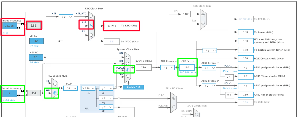
I am using the Nucleo F446RE board and it has both, LSE and HSE crystals on board. The LSE is 32.768 KHz and HSE is of 8MHz. The LSE crystal is used to provide the clock to the RTC whereas the HSE will be used to clock the rest of the system.
In the RCC configuration, enable the crystal oscillator for both LSE and HSE. The image above shows how the clock is configured such that the RTC gets the 32.768KHz, while the rest of the system runs at 180MHz.
If your controller board does not have this dedicated LSE crystal of 32.768KHz, you can use the Internal RC oscillator (LSI RC) too.
STM32 RTC Configuration
The image below shows the RTC configuration.
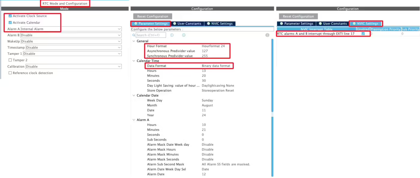
Activate the Clock Source, Calendar and enable at least one of the Alarm.
In the parameter configuration, I have set the 24Hr Time format and Data format is set to binary format. You can set any random values for the time, date and alarm. We will write functions to set up the values for these parameters in the code itself.
The Asynchronous and Synchronous Predivider values are used to calculate the value of the ck_spre. The values should be chosen in a way that the ck_spre value = 1. The formula to calculate ck_spre is shown below.
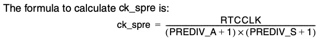
The RTCCLK is at 32768, so using the PREDIV_A value of 127 and PREDEV_S value of 255 in the above formula results in the ck_spre value =1.
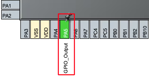
We have also configured the Alarm, so make sure to enable the Alarm interrupt in the NVIC Tab. We will use the LED connected to pin PA5 for the Alarm signal, so let’s set the pin PA5 as output.
I2C Configuration for LCD
I am using the LCD1602 to display the current Time and Date. The LCD is connected using the PCF8574 I2C extender.
The image below shows the I2C configuration.
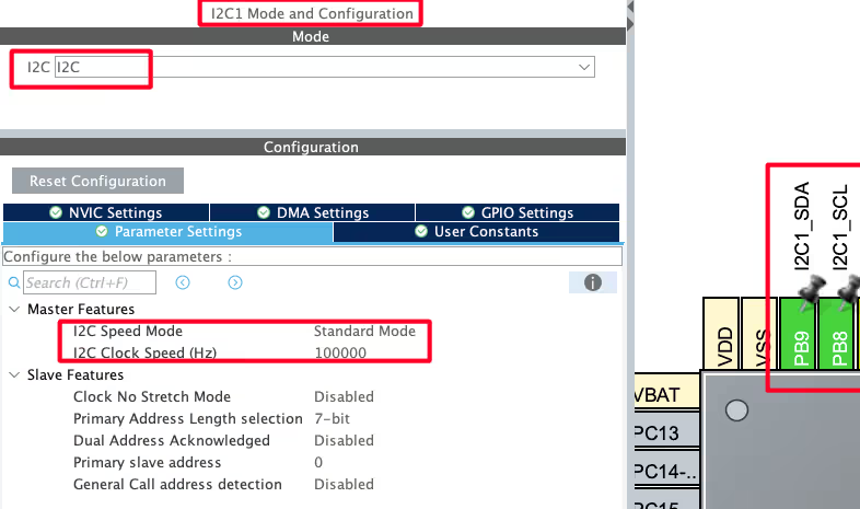
I am using the I2C1 to connect the LCD. The I2C is configured in the standard mode with the clock speed set to 100KHz. The pins PB8 and PB9 are configured as the SCL and SDA pins.
We have already covered how to interface the LCD via I2C with STM32. You can check out the tutorial for more details.
we will program the time to not reset with the board, but this is true as long as the board is connected to the power supply. When you disconnect the power supply, the time will reset and we can’t prevent this from happening.
The only solution is to connect a 3V battery to the VBAT pin of the MCU. Doing this will keep the time running, and it does not matter if the MCU is connected to the power supply or not.
STM32 RTC Source Code and Explanation
We are going to set the time and date in the program itself. So first let’s write a function to set the time and date
RTC Time Setup
The function set_time will be used to configure the current time for the RTC.
I copied this code from the pre-generated function MX_RTC_Init and commented out the code inside the pre-generated function. This is to prevent the RTC from setting the same time after the MCU resets.
void set_time (uint8_t hr, uint8_t min, uint8_t sec)
{
	RTC_TimeTypeDef sTime = {0};
	sTime.Hours = hr;
	sTime.Minutes = min;
	sTime.Seconds = sec;
	sTime.DayLightSaving = RTC_DAYLIGHTSAVING_NONE;
	sTime.StoreOperation = RTC_STOREOPERATION_RESET;
	if (HAL_RTC_SetTime(&hrtc, &sTime, RTC_FORMAT_BIN) != HAL_OK)
	{
		Error_Handler();
	}
}The parameter of the function set_time will be passed to their respective places and the function HAL_RTC_SetTime will set the time to the RTC.
RC Date Setup
The function set_date will be used to configure the current date for the RTC.
void set_date (uint8_t year, uint8_t month, uint8_t date, uint8_t day)  // monday = 1
{
	RTC_DateTypeDef sDate = {0};
	sDate.WeekDay = day;
	sDate.Month = month;
	sDate.Date = date;
	sDate.Year = year;
	if (HAL_RTC_SetDate(&hrtc, &sDate, RTC_FORMAT_BIN) != HAL_OK)
	{
		Error_Handler();
	}

	HAL_RTCEx_BKUPWrite(&hrtc, RTC_BKP_DR1, 0x2345);  // backup register
}This code is again copied from the pre-generated function MX_RTC_Init.
The parameter of the function set_date will be passed to their respective places and the function HAL_RTC_SetDate will set the date to the RTC.
Note here that the day starts with Monday, therefore Monday = 1 and Sunday = 7.
The function HAL_RTCEx_BKUPWrite writes a random value to the backup Register RTC_BKP_DR1. The unique thing about this backup register is that it does not reset when the MCU resets, therefore the value (0x2345 in this case) will always be stored inside this Register, until we change it to some other value.
In the main function, we will read this backup Register. If it has the value we stored (0x2345), we will not update the time again. This prevents our code from writing the same time/date into the RTC every time the MCU resets.
This function HAL_RTCEx_BKUPWrite is being called in the set_date function, so you must call the set_date function in the main function. Otherwise, even the time will not be able to keep up after the reset.
Reading Time and Date from RTC
Below is the function to get the time and date from the RTC.
void get_time_date(char *time, char *date)
{
  RTC_DateTypeDef gDate;
  RTC_TimeTypeDef gTime;

  /* Get the RTC current Time */
  HAL_RTC_GetTime(&hrtc, &gTime, RTC_FORMAT_BIN);
  /* Get the RTC current Date */
  HAL_RTC_GetDate(&hrtc, &gDate, RTC_FORMAT_BIN);

  /* Display time Format: hh:mm:ss */
  sprintf((char*)time,"%02d:%02d:%02d",gTime.Hours, gTime.Minutes, gTime.Seconds);

  /* Display date Format: dd-mm-yyyy */
  sprintf((char*)date,"%02d-%02d-%2d",gDate.Date, gDate.Month, 2000 + gDate.Year);
}The parameters of this function are:
- @time is the pointer to the character array, where the time data will be stored in the character form.
- @date is the pointer to the character array, where the date data will be stored in the character form.
Inside this function, we will first call the functions HAL_RTC_GetTime and HAL_RTC_GetDate to get the time and date in the binary format. The respective data will be stored in the RTC time and date structures.
If you want the data in number form, you can just define these structures globally, and then utilise the time and date data. But here I want to display them on the LCD, so I need to convert them to the character format.
The function sprintf will convert these numeric data in the character format and store them in the respective arrays.
Setting the RTC Alarm
The following function is used to set the ALARM.
void set_alarm (uint8_t hr, uint8_t min, uint8_t sec, uint8_t date)
{
	RTC_AlarmTypeDef sAlarm = {0};
	sAlarm.AlarmTime.Hours = hr;
	sAlarm.AlarmTime.Minutes = min;
	sAlarm.AlarmTime.Seconds = sec;
	sAlarm.AlarmTime.SubSeconds = 0;
	sAlarm.AlarmTime.DayLightSaving = RTC_DAYLIGHTSAVING_NONE;
	sAlarm.AlarmTime.StoreOperation = RTC_STOREOPERATION_RESET;
	sAlarm.AlarmMask = RTC_ALARMMASK_NONE;
	sAlarm.AlarmSubSecondMask = RTC_ALARMSUBSECONDMASK_ALL;
	sAlarm.AlarmDateWeekDaySel = RTC_ALARMDATEWEEKDAYSEL_DATE;
	sAlarm.AlarmDateWeekDay = date;
	sAlarm.Alarm = RTC_ALARM_A;
	if (HAL_RTC_SetAlarm_IT(&hrtc, &sAlarm, RTC_FORMAT_BIN) != HAL_OK)
	{
		Error_Handler();
	}
}The parameters of the function are the date and time when we want the Alarm to trigger. This function is again copied from the pre-generated function MX_RTC_Init and I commented out this code inside the pre-generated function. The parameter of the function set_alarm will be passed to their respective places and the function HAL_RTC_SetAlarm will configure the Alarm in the RTC.
RTC ALARM Event Callback
When the conditions for the Alarm in the RTC are met, an interrupt will trigger and the HAL_RTC_AlarmAEventCallback will be called. We will write our code inside this function.
void HAL_RTC_AlarmAEventCallback(RTC_HandleTypeDef *hrtc)
{
  HAL_GPIO_WritePin (GPIOA, GPIO_PIN_5, 1); // turn on the LED
}Inside this function we will set the pin PA5, which is connected to the LED on board. So the LED will turn on indicating the Alarm.
The main function
int main ()
{
  ....
  lcd_init();
  if (HAL_RTCEx_BKUPRead(&hrtc, RTC_BKP_DR1) != 0x2345)
  {
    set_time(15, 54, 00);
    set_date(24, 8, 11, 7);
  }
set_alarm(15, 55, 0, 11);Inside the main function we will first initialise the LCD. Then we will read the RTC backup Register. If it has the value we stored (0x2345), we will not update the time again. This prevents our code from writing the same time/date into the RTC every time the MCU resets.
But if the value stored in the Backup Register is not equal to 0x2345, that would mean that this is the first time the code is running and hence we need to set the time and date in the RTC. Here I am setting the current time and date. Also set the alarm by calling the set_alarm function.
We will read the time in the while loop as shown below.
  while (1)
  {
    get_time_date(timeData, dateData);
    lcd_put_cur(0,0);
    lcd_send_string(timeData);
    lcd_put_cur(1,0);
    lcd_send_string(dateData);
    HAL_Delay(500);
  }
}Here we will first read time and date data. The data is stored in the arrays, timeData and dateData, in the character form. We will print these arrays on the LCD.
STM32 RTC Result
The gif below shows the result of the above code.

As you can see above, the time is updating every second on the LCD. Also note that as soon as the alarm is triggered, the LED on board tuns ON. This indicates that the Alarm was triggered successfully.
Video Tutorial
STM32 Internal RTC Tutorial
This video explains how to configure and use the internal RTC in STM32 microcontrollers. You will see how to set up the clock, keep track of time using VBAT backup, and display the current date and time in real time. Follow along with the example code to practice and implement RTC in your own projects.
Watch the Video TutorialConclusion
In this tutorial, we learned how to configure and use the internal RTC of STM32 to keep accurate time, including setting the time and understanding the role of RTCCLK, PREDIV_A, and PREDIV_S in generating the 1 Hz clock.
If you need an alternative approach or want to explore external RTC modules, check out our DS3231 RTC tutorial. The DS3231 provides precise, temperature-compensated timekeeping and can be easily interfaced with STM32 via I²C. This is a great follow-up for projects requiring higher accuracy or backup timekeeping.
With this knowledge, you can now confidently implement reliable timekeeping in your STM32 projects, whether using the internal RTC or an external module like the DS3231.
STM32 RTC Project Download
STM32 RTC FAQs


Hello, thank you so much.
I have a problem. May you help me please?
In my project,I don’t use RTC, so the pins of microcontroller for RTC oscillator are not connected.
When the power is connected to my stm32 board, the code isn’t run until I touch the location of RTC Oscillator (32kHz crystal and 2.7pF capacitors).After this, the code is run correctly.
Thank’s for your guidance
Hello, thank you very much for your tuterial.
No matter how you slice it, 0x18 will never equal the year 2018.
it’s in the BCD format.
hi, how can I Download the code?
sAlarm.AlarmDateWeekDaySel = RTC_ALARMDATEWEEKDAYSEL_WEEKDAY;
hi any idea how to set the alarm register if you wantalarm monday to friday.
sAlarm.AlarmDateWeekDay = 1;//Monday
hi, i did simlar project. It works well but except; after soft reset, ı can get correct time but date resets itself. Do you have any suggestion.?
thnx
If you are using F103C8, it have date issues with RTC
add follow Line
void set_alarm(void) {
RTC_AlarmTypeDef sAlarm;
hi
I need a library to drive 16*2 LCD (not i2c version) in CUBE IDE (using HAL) for stm32f103.
can you help me about this?
thank you
The library you are talking about, is already present on this website. Look into STM32.. or just search for Lcd
I have it a good one!
there is something wrong with my code. i try to run it but the pc doesnt register the time on the stm32
I want to use STM32 microcontroller to implement a real time clock. The problem is when the controller has no power, how can I keep the real time clock still going?
you need to connect a battery supply to Vbat pin
use cr2032 battery
Hi
I tried the code but in my screen I can see 00:00:00 01-01-2000
so you have to set date and time in RTC_init function