How to Use SPI with STM32: Step-by-Step Guide
SPI (Serial Peripheral Interface) is one of the most commonly used communication protocols in embedded systems, especially when higher speed and reliable data transfer are required. When working with STM32 microcontrollers, SPI becomes extremely useful for interfacing with external devices such as sensors, displays, memory chips, and many other peripherals.
In this tutorial, we will learn how to use SPI with an STM32 microcontroller step by step. We will start by understanding how SPI works and what the important signals are. Then, we will move on to configuring the SPI peripheral using STM32CubeMX, making sure all the key parameters such as clock polarity, phase, and data size are set correctly.
After the configuration part, we will write the required HAL code to communicate with an SPI device. We will see how to transmit and receive data, how to control the chip-select pin manually, and how to verify that the communication is working properly. To make things practical, we will use the ADXL345 accelerometer as an example device, but the same approach can be applied to almost any SPI-based peripheral.
Introducing the STM32 SPI Peripheral
The SPI (Serial Peripheral Interface) peripheral in STM32 microcontrollers is a high-speed, full-duplex communication interface designed for efficient data exchange between the MCU and external devices such as sensors, displays, memory chips, and other microcontrollers. It supports master and slave modes, allowing the MCU to either control peripheral devices or be controlled by another master. STM32 SPI offers flexible configuration options such as data frame size, clock polarity and phase, and multiple baud rate settings, making it suitable for a wide range of applications.
Some of its important features are:
- Full-Duplex and Half-Duplex Communication – Allows simultaneous data transmission and reception or single-direction communication when required.
- Configurable Clock Settings – Supports multiple clock polarity (CPOL) and clock phase (CPHA) configurations to ensure compatibility with various SPI devices.
- DMA and Interrupt Support – Can be integrated with DMA or interrupt-driven modes for efficient, high-speed data transfers with minimal CPU load.
- Multi-Slave Device Support – Can control multiple slave devices using dedicated chip-select (NSS) pins or software-managed NSS.
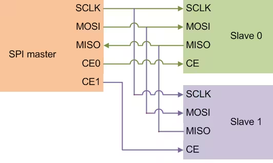
SPI (Serial Peripheral Interface) generally requires 4 wires as shown above. The names are as follows:-
- SCK –> Serial Clock.
- MOSI –> Master out Slave In is used to send data to slave.
- MISO –> Master In Slave Out is used to receive data from slave.
- CE/CS –> Chip Select is used for selecting the slave.
SPI is not very different from I2C. It just require more wires and the process of selecting the slave is a little different. In order to enable a slave device, we need to pull the CS pin low and after our read or write is complete, just pull the pin high again. This will disable the slave device.
We can connect as many slaves as we want, but only 1 can be selected at a time. This is one of the major advantages SPI have over the I2C peripheral, where we can connect a maximum of 128 (27) devices to the same bus.
Common Devices That Use SPI with STM32
You can use SPI to interface STM32 with a variety of components, including:
- Sensors – such as accelerometers, gyroscopes, and magnetometers (e.g., ADXL345, MPU6050 in SPI mode)
- External memory – including Flash memory chips and EEPROM modules
- SD cards – in SPI mode for data logging and storage applications
- Display modules – like TFT LCDs, OLED displays, and other high-speed graphical interfaces
STM32 ADXL345 SPI Wiring Connection
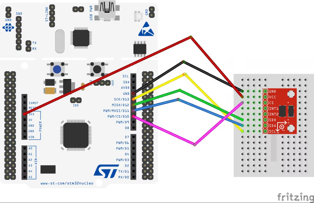
The image below shows the connection between the ADXL345 and the Nucleo-F446.
The sensor is powered with 3.3V from the Nucleo board itself. The pin connections are as follows:
| Nucleo Pin | Sensor Pin | Description |
|---|---|---|
| SCK (Clock) | SCL (Clock) | Provides the clock signal for SPI communication. |
| MISO | SDO (Serial Data Out) | Transfers data from the sensor to the Nucleo. |
| MOSI | SDA (Serial Data) | Transfers data from the Nucleo to the sensor. In SPI mode, this SDA pin acts as SDI (Serial Data Input). |
| CS | CS | Chip Select signal to enable or disable the sensor during communication. |
STM32 CubeMX Configuration
Clock Configuration
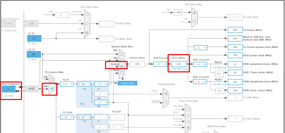
The image below shows the clock configuration for the Nucleo-F446.
I have enabled the External Crystal to provide the clock. The Nucleo F446RE has 8MHz crystal on board and we will use the PLL to run the system at maximum 180MHz.
SPI Configuration
STM32 supports different SPI modes. The mostly used modes are Half Duplex & Full Duplex with Master or Slave modes.
In Half Duplex mode, the SPI uses only 3 wires, CS, SCLK and SDIO. The data is transmitted and received on the same line, therefore the STM32 can either send or receive data at a time.
On the other hand, in Full Duplex mode the SPI uses 4 wires, CS, SCLK, MOSI and MISO. The data is sent by the STM32 on the MOSI line and it is received on the MISO line. Full Duplex mode is used more widely in SPI communication.
As per the ADXL345 datasheet, the maximum SPI clock can be set to 5MHz, so we will keep our SPI clock below this value. Also the sensor follows the SPI MODE 3, CPOL=1, CPHA=1.
The SPI Modes decides on which edge of the clock signal, the data will be sampled and on which edge it will be shifted out. Both Master and slave should be configured to use the same SPI Mode for the transmission to work.
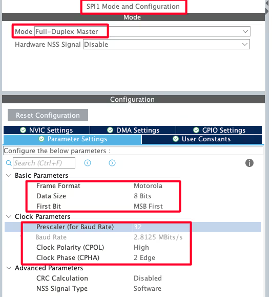
Below is the image showing the SPI configuration. I am using SPI1 for the project.
The SPI is configured in Full Duplex mode, so the STM32 as master can send and receive data at the same time. The Data size is set to 8 Bits because the ADXL345 only supports 8 bit data transfer. The data will be arranged in MSB first format.
I have used the Prescaler of 16 to reduce the SPI clock to 2.8MB/s. This is to make sure that our SPI clock remain lower than 5MB/s (MAX for ADXL345). Also note that the CPOL is HIGH (1) and CPHA is set to 2 edge (CPHA=1).
STM32 SPI Code Example: Read & Write Functions Using HAL
ADXL Write Function
Unlike I2C, the SPI does not have different slave addresses to identify the read and write operations. Therefore the master itself needs to inform the slave whether it wants to perform a write operation or a read operation. Along with that the master also need to inform whether it is performing a multibyte read or write.
Below is the image showing the write operation on the ADXL345 using SPI.
As you can see in the image above, there are 2 additional bits attached with the Address bits. The Address is only 6bit long and then we have the Multibyte (MB) bit and Read Write (R/W) bit. The R/W bit must be set to 0 for the write operation. Also the MB bit should be set to 1 for writing multiple bytes to the device.
Below is the function to write the data to the slave.
void adxl_write (uint8_t Reg, uint8_t data)
{
	uint8_t writeBuf[2];
	writeBuf[0] = Reg|0x40;  // multibyte write enabled
	writeBuf[1] = data;
	HAL_GPIO_WritePin (GPIOB, GPIO_PIN_6, GPIO_PIN_RESET); // pull the cs pin low to enable the slave
	HAL_SPI_Transmit (&hspi1, writeBuf, 2, 100);  // transmit the address and data
	HAL_GPIO_WritePin (GPIOB, GPIO_PIN_6, GPIO_PIN_SET); // pull the cs pin high to disable the slave
}The parameter of the function adxl_write are:
- @Reg is the register address inside the slave device, where the master wants to write the data to.
- @data is the data, the master wants to store in the above address.
Since we are writing 2 bytes, register address and data, we need to store both the bytes in an array. Then set the R/W bit to 0 for write operation and MB bit to 1 for multibyte operation. Our final data for the first byte transfer will be b01xxxxxx. Here the ‘x’ represents the 5 bit register address.
To send the data via the SPI, we need to follow the procedure as mentioned below.
- Pull the CS low to select the slave.
- Call the function
HAL_SPI_Transmitto transmit the 2 byte array we just defined. The timeout for the transfer operation is set to 100ms. - Pull the CS pin high to disable the slave.
ADXL Read Function
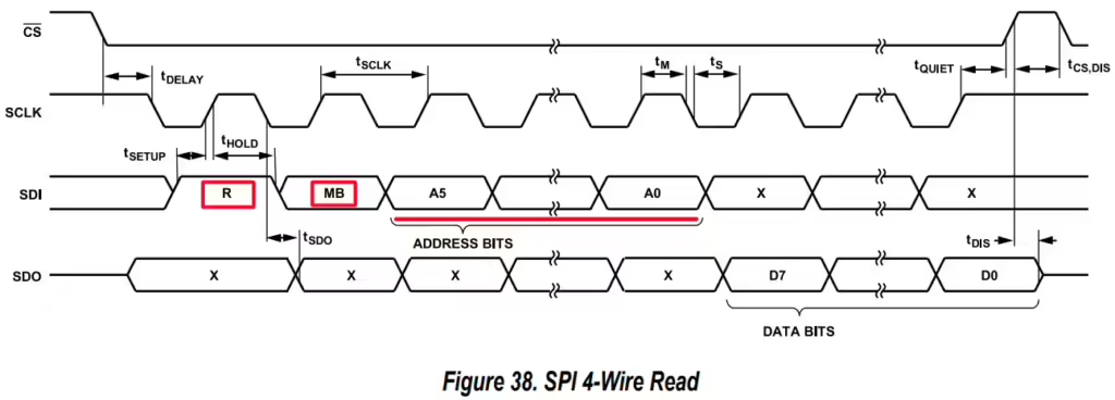
Just like write operation, the master needs to inform the slave that this is a read operation. To do so, the R/W but must be set to 1, indicating the Read command.
Below is the image showing the write operation on the ADXL345 using SPI.
As you can see in the image above, there are 2 additional bits attached with the Address bits. The Address is only 6bit long and then we have the Multibyte (MB) bit and Read Write (R/W) bit. The R/W bit must be set to 1 for the read operation. Also the MB bit should be set to 1 for reading multiple bytes from the device.
Below is the function to read the data from the slave.
void adxl_read (uint8_t Reg, uint8_t *Buffer, size_t len)
{
	Reg |= 0x80;  // read operation
	Reg |= 0x40;  // multibyte read
	HAL_GPIO_WritePin (GPIOB, GPIO_PIN_6, GPIO_PIN_RESET);  // pull the cs pin low to enable the slave
	HAL_SPI_Transmit (&hspi1, &Reg, 1, 100);  // send the address from where you want to read data
	HAL_SPI_Receive (&hspi1, Buffer, len, 100);  // read 6 BYTES of data
	HAL_GPIO_WritePin (GPIOB, GPIO_PIN_6, GPIO_PIN_SET);  // pull the cs pin high to disable the slave
}The parameter of the function adxl_write are:
- @Reg is the register address inside the slave device, where the master wants to read the data from.
- @Buffer is the pointer to the buffer where the the received data will be stored.
- @len is the number of bytes, the master wants to read.
The R/W bit must be set to 1 for read operation and MB bit to 1 for multibyte operation. Our final data for the Register Address will be b11xxxxxx. Here the ‘x’ represents the 5 bit register address.
To read the data via the SPI, we need to follow the procedure as mentioned below.
- Pull the CS low to select the slave.
- Call the function
HAL_SPI_Transmitto transmit the modified register address, where we want to read the data from. The timeout for the transfer operation is set to 100ms. - Call the function
HAL_SPI_Receiveto receive the data from the slave device. The 6 bytes of data will be stored in the Buffer array. - Pull the CS pin high to disable the slave.
ADXL Initialization
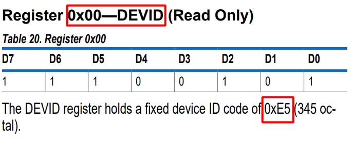
We will first check if the slave device is responding, by reading the ID Register (0x00). The ADXL should respond with the value 0xE5.
void adxl_init (void)
{
	uint8_t chipID=0;
adxl_read(0x00, &chipID, 1);If the DEV_ID returned is 0xE5, we will proceed with the initialisation.
Now we will modify POWER_CTL Register (0x2D) and DATA_FORMAT Register (0x31). First RESET all bits of POWER_CTL register by writing 0 to them.
	if (chipID == 0xE5)
	{
		adxl_write (0x2d, 0x00);  // reset all bits; standby
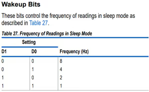
adxl_write (0x2d, 0x08); // measure=1 and wake up 8hzSet the MEASURE bit, RESET the SLEEP bit and SET the frequency in the WAKE UP bits
Next, in the DATA_FORMAT Register, Set the RANGE using D0 and D1.
		adxl_write (0x31, 0x01);  // 10bit data, range= +- 4g
	}
}The main function
Inside the main function, we will first initialise the ADXL.
int main()
{
  ....
adxl_init(); // initialize adxlWe will write the rest of the code in the while loop.
  while (1)
  {
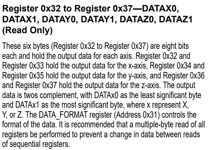
adxl_read (0x32, RxData, 6);Here we will first read 6 bytes starting from the Register 0x32. The data is stored in the Registers 0x32 to 0x37 in the form of DATA X0, DATA X1, DATA Y0, DATA Y1, DATA Z0, DATA Z1.
Now we need to combine the DATA X0, DATA X1 into single 10 bit value and this can be done by
	  int16_t x = ((RxData[1]<<8)|RxData[0]);
          int16_t y = ((RxData[3]<<8)|RxData[2]);
int16_t z = ((RxData[5]<<8)|RxData[4]);Next we will convert this data into the g form in order to check for the acceleration in specific axis. As you can check above in the initialisation part, we have set the range of ±4 g. According to the datasheet, for the range of ±4 g, the sensitivity is 128LSB/g.
So to convert into g-force, we need to divide the value by 128.
      xg = (float)x/128;
      yg = (float)y/128;
      zg = (float)z/128;

      HAL_Delay(1000);
  }
}STM32 SPI Result
You can check the result in the live expression of the debugger console. The image below shows the output on the console.
The image above shows the acceleration in all 3 axes when the sensor is placed normally on the table. The Acc in z axis is 1g, while in other axes, it is close to 0.
The image above shows the acceleration when the sensor is tilted in the y axis. The Acc in y-axis is -1g, while the other axes are close to 0.
Video Tutorial
STM32 SPI Communication – Video Tutorial
In this tutorial, we learn how to configure and use SPI communication with STM32 microcontrollers step by step. Along with the written explanation, we have also created a practical video tutorial where we go through the complete process together — starting from wiring the SPI device, configuring SPI in STM32CubeMX, and finally writing the transmit and receive code using HAL. You can watch the video alongside this article and follow each step to see how SPI communication works in a real project.
Watch the STM32 SPI Video TutorialConclusion
In this tutorial, we covered how to use SPI communication with an STM32 microcontroller from start to finish. We went through the basics of SPI, understood the purpose of each signal, configured the SPI peripheral using STM32CubeMX, and wrote the required HAL code to transmit and receive data. Using the ADXL345 accelerometer as an example, we also saw how to read device registers, control the chip-select line manually, and verify that the communication is working correctly.
Understanding SPI is extremely useful when working with STM32, as many high-speed peripherals rely on this protocol. The concepts shown in this tutorial can be directly applied to other SPI devices such as displays, flash memory, DACs, and different types of sensors. Once you are comfortable with basic SPI communication, you can further extend this knowledge to use interrupt or DMA-based transfers for more efficient and advanced applications.
Browse More STM32 SPI Tutorials
STM32 SPI Tutorial Using Registers (Full-Duplex Master with ADXL345)
W25Q Flash Series Part 1 – Connect and Read Device ID
W25Q Flash Series Part 2 – Read Data from Device
W25Q Flash Series Part 3 – How to Erase Sectors
W25Q Flash Series Part 4 – How to Program Pages
W25Q Flash Series Part 5 – how to update sectors
W25Q Flash Series Part 6 – Integers floats and 32bit Data
STM32 SPI Project Download
Info
You can help with the development by DONATING Below.
To download the project, click the DOWNLOAD button.
STM32 SPI FAQs
The ADXL345 requires SPI Mode 3 (CPOL = 1, CPHA = 1) and a clock frequency below 5 MHz. In the tutorial example, a prescaler of 16 with an 80 MHz APB clock yields ~5 MHz, making it compatible and reliable.
In STM32CubeMX, set the SPI peripheral to Full‑Duplex, 8‑bit data, MSB first, and choose Mode 3. Configure a prescaler to keep SCK under 5 MHz. In the HAL code, ensure HAL_SPI_Init() matches these settings.
You must manually toggle the CS pin: pull CS LOW before starting a transfer and HIGH afterward. This ensures that the slave device, like the ADXL345, correctly receives each command or data packet.
Write (SPI Transmit): Send the register address (with write bit) followed by data bytes.
Read (SPI Receive): Transmit the register address with the READ (0x80) bit set (and MULTI‑BYTE (0x40) if needed), then read back the data. Data concatenation and conversion are handled afterwards
After receiving six bytes corresponding to the X, Y, and Z axes from registers 0x32–0x37, combine each axis's high and low byte. Convert the 16-bit result into g‑units using the sensor’s sensitivity scale (e.g. for ±4 g range, divide by 128) to get real-world acceleration values in g or m/s².









hi, i try the above step to implement spi1 in stm32f3 register all are same but i am not 100% during the transmission and reception i am getting some garbage data in the receiver buffer when check the spi->dr i found it showing 0xffff please suggest me what could i have done wrong so that spi1 work correctly.
can you use SPI in PL1167?
YOU can use the AD7705 , it also use the SPI to communication to the MCU , but if you use AD7705 ,you must modification the parameter
Hello, I have tried your same code for ADXL375 using a STM32F401 and truestudio. I have put the right values for the cpol and the cpha and my speed is less than 5MHz. However, when i try getting the device ID i get rubbish (the value changes each time i run the program) and when i read the different axes I get really strange values especially for the z axis. Basically, nothing is working. While debugging it seems that only MOSI line is working (MISO no). I have measured with oscilloscope as well but got no clear information. I really dont know what else to do. if you know what it could be it would help a lot.
Don’t use SPI. First Try using I2C I have written a tutorial using I2C. You can search that wihtin the website itself.
I am using SPI because I am programming various ADXL375, so I would like to be able to at least gather measurements from one