Home ▸ STM32 Tutorials ▸
Updated On: March 23, 2026
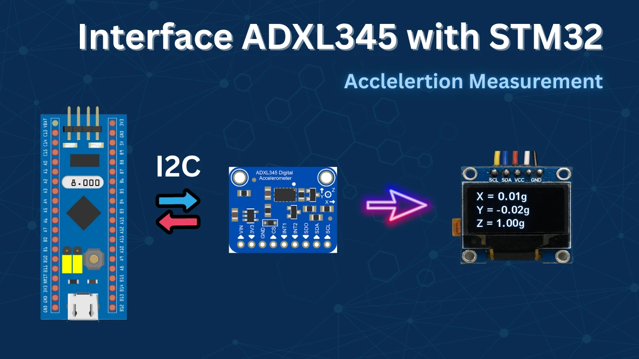
ADXL345 + STM32 I2C Tutorial: Read 3-Axis Acceleration Data
In this tutorial, you’ll learn how to interface the ADXL345 3-axis accelerometer with an STM32 microcontroller using the I2C communication protocol. We’ll configure the sensor registers using STM32 HAL functions and read real-time acceleration data along the X, Y, and Z axes.
You’ll also learn how to display the sensor data on an OLED screen, providing visual feedback for motion and tilt. The tutorial includes:
- Basic overview of the ADXL345 sensor
- Hardware connections between STM32, ADXL345, and OLED
- STM32CubeMX setup for I2C and GPIO
- HAL-based initialization and data reading
- Real-time data display on OLED
- Code walkthrough and explanations
Related Tutorials You Might Like
- MPU6050 with STM32 (Gyro + Accelerometer)
- SSD1306 OLED Display with STM32 using I2C
- Using SPI with STM32 (Alternate ADXL345 method)
These resources complement this guide and help expand your understanding of motion sensing and display interfacing with STM32.
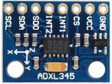
Introducing ADXL345 Accelerometer
The ADXL345 is a small, thin, ultra-low power 3-axis accelerometer that measures acceleration in the X, Y, and Z axes. It is widely used in motion sensing, gesture detection, tilt measurement, and vibration monitoring applications. The sensor communicates over I²C or SPI and offers high resolution (up to 13 bits) even at low power consumption. Its built-in features like tap detection, free-fall sensing, and activity monitoring make it ideal for wearable devices, handheld gadgets, and embedded systems like STM32.
Key Features of ADXL345:
- 3-Axis Acceleration Measurement: Measures acceleration in X, Y, and Z directions with a selectable range of ±2g, ±4g, ±8g, and ±16g.
- High Resolution Output (13-bit): Provides 13-bit resolution with sensitivity up to 3.9 mg/LSB, ensuring accurate motion tracking even at low g-ranges.
- Digital Interface (I²C or SPI): Supports both I2C and SPI digital communication, making it flexible for various microcontroller platforms.
- Advanced Motion Detection Features: Includes built-in single tap, double tap, activity, inactivity, and free-fall detection capabilities for gesture-based applications.
Why should you use ADXL345?
The ADXL345 is an excellent choice for motion-sensing applications due to its simplicity, accuracy, and versatility. It offers 3-axis acceleration measurement with a high resolution of up to 13 bits, making it suitable for both static and dynamic acceleration detection like tilt sensing, vibration monitoring, and free-fall detection.
It supports both I²C and SPI communication, making it easy to interface with a wide range of microcontrollers, including STM32. With its built-in tap detection, activity/inactivity sensing, and low power consumption, the ADXL345 is ideal for portable, battery-powered, and gesture-controlled devices.
Whether you’re building a step counter, fall detector, or interactive system, the ADXL345 provides a reliable and cost-effective solution.
Wiring Diagram
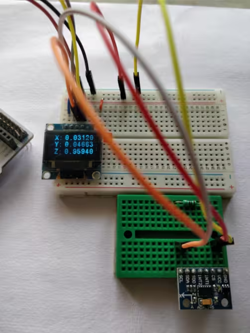
The connection between STM32F446 and ADXL345 using the I2C peripheral is shown in the image below. The 0.96″ Oled display is also connected to the same I2C pins.
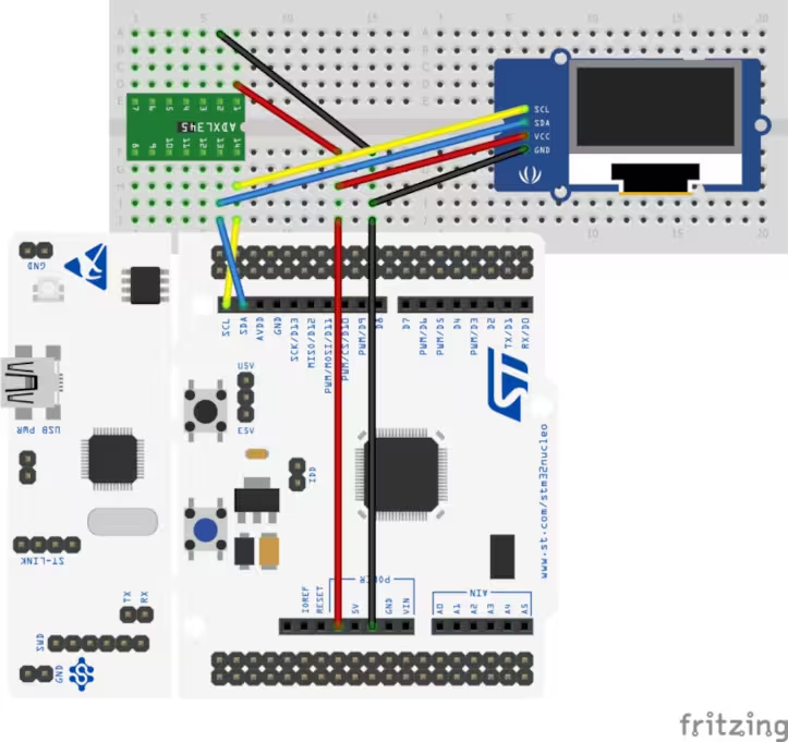
The pin connection is shown in the table below.
| Component | Pin Name | Connected To (STM32 Nucleo) | Wire Color |
|---|---|---|---|
| ADXL345 | VCC | 3.3V | Red |
| GND | GND | Black | |
| SDA | PB9 (I2C1_SDA) | Green | |
| SCL | PB8 (I2C1_SCL) | Yellow | |
| OLED Display | VCC | 3.3V | Red |
| GND | GND | Black | |
| SDA | PB9 (I2C1_SDA) | Blue | |
| SCL | PB8 (I2C1_SCL) | Orange |
STM32CubeMX Configuration
In this project, we’ll enable I2C1 in STM32CubeMX to communicate with both the ADXL345 accelerometer and the OLED display. Pins PB8 (SCL) and PB9 (SDA) are assigned for I2C communication. After setting up the clock and I2C, we’ll generate the code using STM32CubeIDE for further development.
Clock Configuration
Below is the image showing the clock configuration for this project.
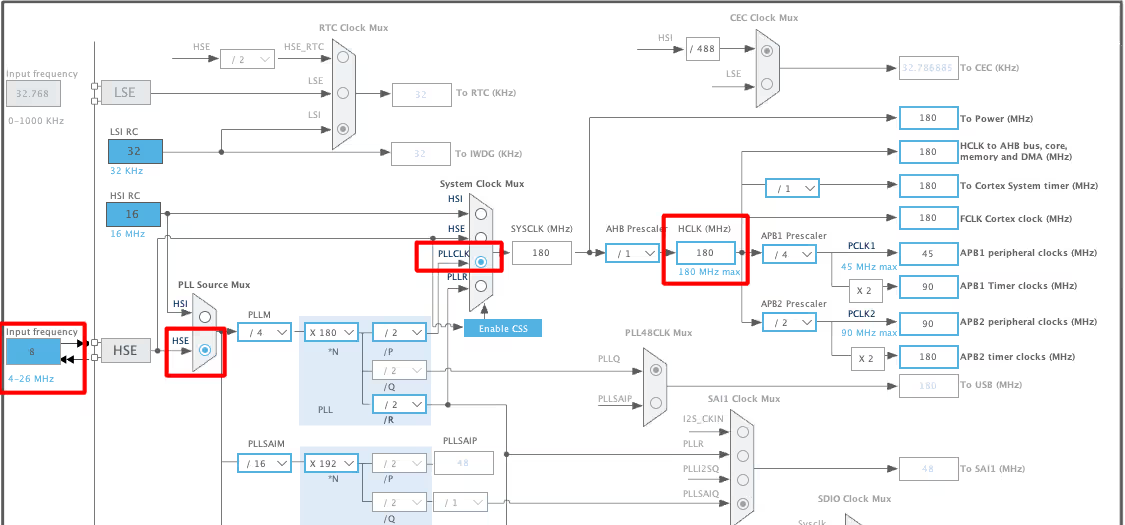
I have enabled the External Crystal to provide the clock. The Nucleo F446RE has 8MHz crystal on board and we will use the PLL to run the system at maximum 180MHz.
I2C Configuration
Below is the image showing the I2C configuration.
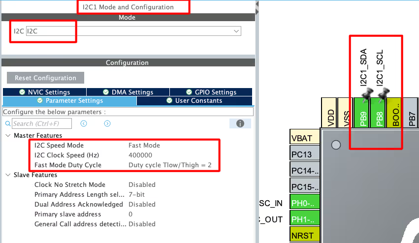
I am using I2C1 to connect both, Oled Display and ADXL345 sensor. The I2C is configured in the FAST MODE with the clock speed of 400KHz. This is as per the sensor’s requirement. The pins PB8 and PB9 are configured as the SCL and SDA pins.
STM32 HAL Code Implementation
Let’s start with the definitions first.
Definition
First we will define an array to store the data received from the sensor. Also define the float variables to store the converted data in terms of the g force.
#define ADXL_Address 0x53<<1
uint8_t RxData[10];
float xg, yg, zg;As per the datasheet, the slave Address of the ADXL345 is 0xA6. This is the write address of the device and the HAL library will take care of the read address by itself.

Initialization
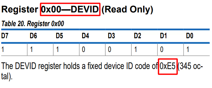
We will first check if the slave device is responding, by reading the ID Register (0x00). The ADXL should respond with the value 0xE5.
void ADXL_Init (void)
{
	uint8_t chipID=0;
ADXL_Read(0x00, &chipID, 1);If the DEV_ID returned is 0xE5, we will proceed with the initialization.
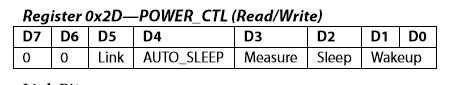
In order to initialize the sensor, we will modify POWER_CTL Register (0x2D) and DATA_FORMAT Register (0x31).
First RESET all bits of POWER_CTL register by writing 0 to them.
	if (chipID == 0xE5)
	{
		ADXL_Write_Reg (0x2d, 0x00);  // reset all bits; standby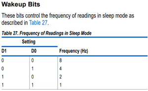
ADXL_Write_Reg (0x2d, 0x08); // measure=1 and wake up 8hzThen SET the MEASURE bit, RESET the SLEEP bit and SET the frequency in the WAKE UP bits
Next, in the DATA_FORMAT Register, Set the RANGE using D0 and D1.
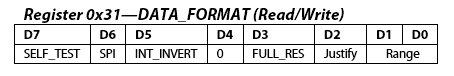
		ADXL_Write_Reg (0x31, 0x01);  // 10bit data, range= +- 4g
	}
}The main function
Inside the main function, we will first initialise the Oled and the ADXL.
int main()
{
  ....
  SSD1306_Init();  // initialize OLED display
  SSD1306_GotoXY (1, 1);
  SSD1306_Puts ("Initializing...", &Font_11x18, 1);
  SSD1306_UpdateScreen ();  // update display

  ADXL_Init();  // initialize adxl
SSD1306_Clear();We will write the rest of the code in the while loop.
  while (1)
  {
ADXL_Read(0x32, RxData, 6);Here we will first read 6 bytes starting from the Register 0x32. The data is stored in the Registers 0x32 to 0x37 in the form of DATA X0, DATA X1, DATA Y0, DATA Y1, DATA Z0, DATA Z1.
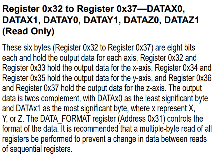
Now we need to combine the DATA X0, DATA X1 into single 10 bit value and this can be done by
	  int16_t RAWX = ((RxData[1]<<8)|RxData[0]);
	  int16_t RAWY = ((RxData[3]<<8)|RxData[2]);
int16_t RAWZ = ((RxData[5]<<8)|RxData[4]);Next we will convert this data into the g force to check for the acceleration in specific axis. As you can check above in the initialisation part, we have set the range of ±4 g. According to the datasheet, for the range of ±4 g, the sensitivity is 128LSB/g.
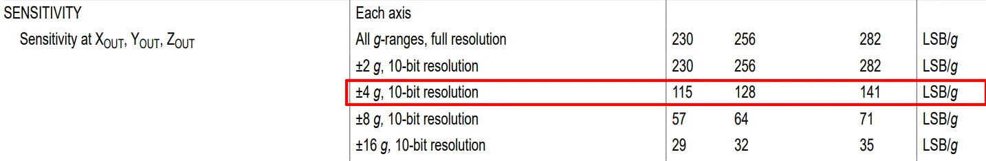
So to convert into g, we need to divide the value by 128.
	  xg = (float)RAWX/128;
	  yg = (float)RAWY/128;
zg = (float)RAWZ/128;Now we can display this data on the display. We will call the function display_data to display the float value on the oled. This function is explained below.
	  SSD1306_GotoXY (16, 1);
	  SSD1306_Puts ("X: ", &Font_11x18, 1);
	  SSD1306_GotoXY (32, 1);
	  display_data (xg);

	  SSD1306_GotoXY (16, 20);
	  SSD1306_Puts ("Y: ", &Font_11x18, 1);
	  SSD1306_GotoXY (32, 20);
	  display_data (yg);

	  SSD1306_GotoXY (16, 40);
	  SSD1306_Puts ("Z: ", &Font_11x18, 1);
	  SSD1306_GotoXY (32, 40);
	  display_data (zg);

	  HAL_Delay (500);
   }
}Here we are displaying the data for all three axis in different rows.
Below is the function display_data.
void display_data (float data)
{
    char axischar[5];
    sprintf (axischar, "%.2f", data);
    SSD1306_Puts (axischar, &Font_11x18, 1);
    SSD1306_UpdateScreen ();  // update display
}Here we will first convert the float data into the ascii format and then send the converted array to the display.
Result of ADXL345 on the Oled Display
Below are the images showing the Acceleration in different Axes on the Oled display.
Acceleration in Z-Axis
Below is the image showing the result when the sensor is placed on the z-axis. The Acceleration in Z-Axis is around 1g, while the other Axes are around 0g.
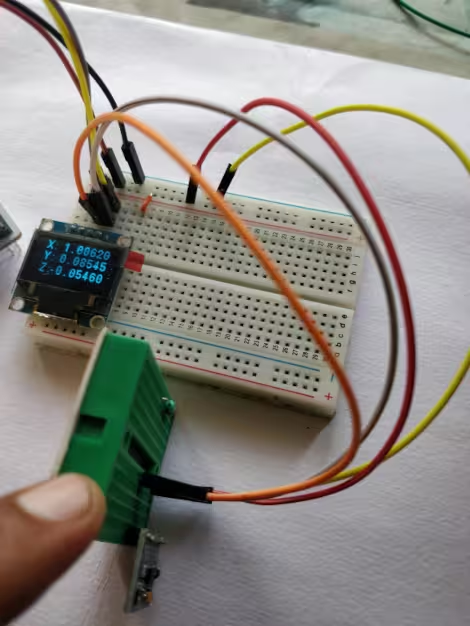
Acceleration in X-Axis
Below is the image showing the result when the sensor is placed on the x-axis. The Acceleration in X-Axis is around 1g, while the other Axes are around 0g.
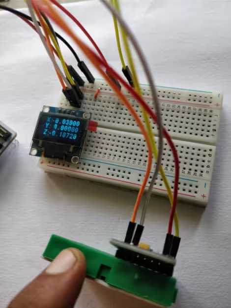
Acceleration in Y-Axis
Below is the image showing the result when the sensor is placed on the y-axis. The Acceleration in Y-Axis is around 1g, while the other Axes are around 0g.
VIDEO TUTORIAL
STM32 ADXL345 Accelerometer Tutorial Video
This tutorial shows how to interface the ADXL345 3-axis accelerometer with an STM32 microcontroller using CubeMX and HAL. You’ll learn how to configure the STM32 for I2C communication, read real-time acceleration data from the X, Y, and Z axes, and display the values on a 0.96″ OLED screen. The video walkthrough demonstrates the complete setup, including wiring, sensor initialization, and live data reading, giving you a clear understanding of motion detection and tilt sensing with STM32.
Watch the VideoConclusion
In this tutorial, we successfully interfaced the ADXL345 3-axis accelerometer with an STM32 microcontroller via the I2C protocol. Using STM32CubeMX for configuration, we were able to read real-time acceleration data from the sensor and display the X, Y, and Z axis values on a 0.96″ OLED screen. The project demonstrates how easy it is to combine STM32, sensors, and displays to create interactive embedded systems.
This setup is an excellent starting point for applications such as motion detection, tilt sensing, and other sensor-based projects. With minimal wiring and HAL-based programming, it offers a simple, efficient, and beginner-friendly approach, making it ideal for hobbyists and those new to STM32 development.
You can check out the similar STM32 tutorials:
Checkout More STM32 Sensors Tutorials
How to Interface DHT11 Temperature and Humidity Sensor with STM32 using HAL
Interface AHT20 Sensor with STM32 Using I2C
How to Interface SHT21 Sensor with STM32 using I2C (Step-by-Step with Code and Circuit Diagram)
Interface BME280 Sensor with STM32 — Read Temp, Humidity & Pressure
STM32 DHT22 Temperature & Humidity Sensor with HAL

Multiple DS18B20 sensors using UART
How to interface MPU6050 (GY-521) with STM32
STM32 ADXL345 Project Download
STM32 ADXL345 FAQs


The reason why you are getting 65535 value; the hex value of -1 in signed int16_t form is 0xFFFF. However, if you store it in the uint16_t variable, it will be read as 65535. I am assuming that the default acceleration value at rest is -1g.
stm32 – How to read data from MPU6050 using STM32F4 – Stack Overflow
@Anil
Hi,
How to initialise the LIS3DH sensor?
You have not enabled the sleep mode (SLEEP bit is 0) so measure and wakeup at 8Hz is of no use. The data rates can be set by ‘Register 0x2C—BW_RATE’. Am I right?
Hello, I m follow above step but my end ADXL345 sensor given 65535 output value…how to resolve these problem…
follow this, it will help you resolve it, https://www.engineersgarage.com/adxl345-accelerometer-arduino-i2c/
it’s for arduino, but just focus on how he did the formatting of data
DONATE and DOWNLOAD links don’t work.
It’s fixed now.. Thanks for informing
sorry for too much specific question, in general what would you have searched in case you need to make freefall example for your sensor in application notes or datasheet
freefall means the “g” value will change. The acceleration of the free fall (If you know basic physics)
anyone know free-fall example for lis3dsh on accelerator by following ST application notes (doc no. AN3393) section 9.3. free-fall but couldn’t get the interrupt for free fall
hi.how can i show ADC value on the oled lcd?