

Home ▸ STM32 Tutorials ▸
Updated On: November 1, 2026
STM32 Flash Programming with HAL: Erase, Write and Read Data
The internal flash of an STM32 holds the firmware, and the unused part of it can also store calibration values, configuration settings, device IDs, and counters that must survive a power cycle. Flash behaves differently from RAM. A location cannot be overwritten directly, erasing works on fixed blocks, and a write to the wrong address can corrupt the firmware that is currently running.
This tutorial shows how to program the internal flash with the HAL library for both common layouts. The first part covers page-based flash on the STM32F1, where pages are small and easy to manage. The second part covers sector-based flash on the STM32F4 and H7, where sectors are larger and the addresses need more careful planning. Both parts include the complete write, read, and erase code, tested with arrays, strings, integers, and floats and checked in a memory viewer.
Once you can store data in internal flash, the STM32 custom bootloader series is a good next step, because it uses the same flash operations for application validation and firmware updates. If your project needs more space than the internal flash offers, the W25Q external flash series covers an SPI flash chip.
Table of contents
STM32 Flash Memory Basics
Flash is a type of non-volatile memory, which means it keeps its contents when the power is off. RAM loses its contents at every reset. On an STM32 the program code runs directly from flash, and any area that the code does not use can hold data that has to stay in place after a restart or a power loss.
Flash has two properties that make it different from RAM. The first is that a location cannot simply be overwritten. The block that contains it has to be erased first, and only then can new values be written. The second is that erasing works on whole blocks and not on single bytes, so STM32 devices organize their flash in either pages or sectors. Flash also has a limited number of erase cycles, which is a good reason to write to it only when the data actually changes.
STM32 Page-Based vs Sector-Based Flash
STM32 devices use one of two flash layouts, and it is important to know which one your device has before you write any code.
- Page-based flash is used in the STM32F1 and in the Cortex-M0 families such as the F0. The memory is divided into small pages, usually 1 KB or 2 KB each, and one page can be erased at a time. Erasing a page clears everything inside it, so changing a single variable still means erasing and rewriting the whole page.
- Sector-based flash is used in the STM32F4 and H7. A sector can range from a few KB to over a hundred KB, so the layout is more flexible, but an erase removes a much larger area. The data storage has to be planned so that an erase does not remove anything that is still needed.
The table below compares the two layouts.
| Feature | Page-based flash (STM32F1, F0) | Sector-based flash (STM32F4, H7) |
|---|---|---|
| Memory unit | Pages | Sectors |
| Typical size | 1 KB to 2 KB per page | A few KB up to tens of KB per sector |
| Erase granularity | One page at a time | One sector at a time |
| Complexity | Simple and easy to manage | Needs more careful planning |
| Updating small data | Easy, but the whole page is erased | May erase a large sector for a small change |
| Best suited for | Small devices and small applications | Larger devices and larger applications |
The most common mistake with sector-based flash is to underestimate how large the sectors are. The STM32F446, for example, has sectors from 16 KB to 128 KB. If you write a 4-byte value into a sector that also holds other data, the erase removes all of that data. For this reason, the data storage should always be placed in a sector that no other code uses.
STM32 HAL Flash Functions: Unlock, Erase, Write and Read
Flash must be unlocked before any write or erase operation. Reading does not need an unlock. The usual pattern is to unlock the flash, do the work, and lock it again.
HAL_FLASH_Unlock();   // Enable write/erase access
// ... operations ...
HAL_FLASH_Lock(); // Re-protect after finishingAn erase is done for a page or a sector with HAL_FLASHEx_Erase().
HAL_FLASHEx_Erase(&EraseInitStruct, &PageOrSectorError);Data is written one word at a time with HAL_FLASH_Program().
HAL_FLASH_Program(FLASH_TYPEPROGRAM_WORD, address, data);
// Increment address by 4 per word (use 2 for half-word, 8 for double-word)Reading is a direct access through a pointer, and no unlock is needed.
uint32_t value = *(__IO uint32_t*)address;On the H7 and H5 families the programming type and the data argument of HAL_FLASH_Program() are different, because these devices write a full flash word at once. The H7 project files linked later in this post show the correct version for those devices.
Clear the Flash Error Flags on STM32H5, G4 and L4
On the STM32H5, G4, and L4, a flag left over from an earlier operation can make the next erase fail, even when the erase itself is valid. To avoid this, clear the error flags right after unlocking the flash and before the erase:
HAL_FLASH_Unlock();
__HAL_FLASH_CLEAR_FLAG(FLASH_FLAG_ALL_ERRORS);
// erase and write here
HAL_FLASH_Lock();STM32 Page-Based Flash Programming (F1)
This section uses the STM32F103 on the BluePill board. Its flash has 128 pages of 1 KB each, which makes 128 KB in total, and it starts at the address 0x08000000. Some BluePill boards are sold with a 64 KB chip, so check your device before you use the pages at the end of the flash. The image below shows the layout.
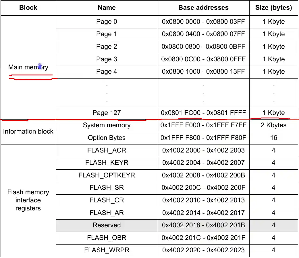
The firmware is stored from the start of the flash, so the data area has to stay away from it. For a real product, the last page is the safest choice. On this device it covers the addresses from 0x0801FC00 to 0x0801FFFF. Every page is 1 KB, so the start address of page n is 0x08000000 + n × 1024. The examples below use addresses further inside the flash, which is acceptable here because the test project is very small.
Page-Based Flash Write Function
The function below erases the pages that the data will occupy and then writes the data.
uint32_t Flash_Write_Data (uint32_t StartPageAddress, uint32_t *Data, uint16_t numberofwords)
{

	static FLASH_EraseInitTypeDef EraseInitStruct;
	uint32_t PAGEError;
	int sofar=0;

	  /* Unlock the Flash to enable the flash control register access *************/
	   HAL_FLASH_Unlock();

	   /* Erase the user Flash area*/

	  uint32_t StartPage = GetPage(StartPageAddress);
	  uint32_t EndPageAdress = StartPageAddress + numberofwords*4;
	  uint32_t EndPage = GetPage(EndPageAdress);

	   /* Fill EraseInit structure*/
	   EraseInitStruct.TypeErase   = FLASH_TYPEERASE_PAGES;
	   EraseInitStruct.PageAddress = StartPage;
	   EraseInitStruct.NbPages     = ((EndPage - StartPage)/FLASH_PAGE_SIZE) +1;

	   if (HAL_FLASHEx_Erase(&EraseInitStruct, &PAGEError) != HAL_OK)
	   {
	     /*Error occurred while page erase.*/
		  HAL_FLASH_Lock();
		  return HAL_FLASH_GetError ();
	   }

	   /* Program the user Flash area word by word*/

	   while (sofar<numberofwords)
	   {
	     if (HAL_FLASH_Program(FLASH_TYPEPROGRAM_WORD, StartPageAddress, Data[sofar]) == HAL_OK)
	     {
	    	 StartPageAddress += 4;  // use StartPageAddress += 2 for half word and 8 for double word
	    	 sofar++;
	     }
	     else
	     {
	       /* Error occurred while writing data in Flash memory*/
	    	 HAL_FLASH_Lock();
	    	 return HAL_FLASH_GetError ();
	     }
	   }

	   /* Lock the Flash to disable the flash control register access (recommended
	      to protect the FLASH memory against possible unwanted operation) *********/
	   HAL_FLASH_Lock();

	   return 0;
}The function takes three parameters:
StartPageAddressis the address in flash where the writing starts. It can be the first address of a page or any address inside a page.Datais a pointer to the array of 32-bit values that will be written.numberofwordsis the number of 32-bit words to write.
The function works in the following order:
- It unlocks the flash so that the control registers can be accessed.
- It calculates the first and the last page that the data will cover, based on the start address and the number of words.
- It erases those pages, because flash must be erased before new data is written.
- It writes the data one word at a time.
- It returns an error code if the erase or a write fails, and it locks the flash before it returns.
- It locks the flash again when the writing is finished, which protects the memory from accidental writes.
The helper function GetPage() converts an address into the start address of the page that contains it. It is part of the project files linked at the end of this post.
Page-Based Flash Read Function
Reading needs no unlock and no erase. The function below copies the requested number of words from flash into a buffer.
void Flash_Read_Data (uint32_t StartPageAddress, uint32_t *RxBuf, uint16_t numberofwords)
{
	while (numberofwords--)
	{
		*RxBuf = *(__IO uint32_t *)StartPageAddress;
		StartPageAddress += 4;
		RxBuf++;
	}
}The function reads one 32-bit word from the current flash address into the buffer, moves both the flash address and the buffer pointer forward by four bytes, and repeats this until the requested number of words has been copied.
Page-Based Flash Usage Example
The example below writes an array, a string, an integer, and a float into flash and reads each of them back.
char *data = "hello FLASH from ControllerTech\
	      This is a test to see how many words can we work with";

uint32_t data2[] = {0x1,0x2,0x3,0x4,0x5,0x6,0x7,0x8,0x9};
uint32_t Rx_Data[30];
char string[100];

int number = 123;
float val = 123.456;
float RxVal;

  Flash_Write_Data(0x08004410 , (uint32_t *)data2, 9);
  Flash_Read_Data(0x08004410 , Rx_Data, 9);


  int numofwords = (strlen(data)/4)+((strlen(data)%4)!=0);
  Flash_Write_Data(0x08004810 , (uint32_t *)data, numofwords);
  Flash_Read_Data(0x08004810 , Rx_Data, numofwords);
  Convert_To_Str(Rx_Data, string);


  Flash_Write_NUM(0x08005C10, number);
  RxVal = Flash_Read_NUM(0x08005C10);

  Flash_Write_NUM(0x08012000, val);
RxVal = Flash_Read_NUM(0x08012000);Each part of the example works as follows:
- Character string: The string is stored as 32-bit words, so the number of words is the string length divided by four and rounded up. The string is written with
Flash_Write_Data(), read back withFlash_Read_Data(), and turned into readable text withConvert_To_Str(). - Integer and float: The values are written and read with
Flash_Write_NUM()andFlash_Read_NUM(), each at its own flash address. - Array of 32-bit values: The array
data2is written to flash and read back intoRx_Dataso that the content can be compared.
The functions Flash_Write_NUM(), Flash_Read_NUM(), and Convert_To_Str() are included in the project files at the end of this post.
Page-Based Flash Test Result
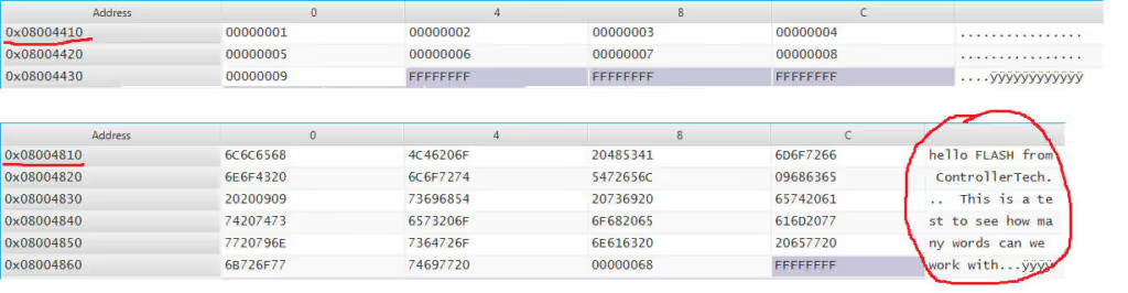
The memory viewer in the image above shows the content of the flash after the array and the string were written. In the first table, the array data2 starts at 0x08004410, and each cell holds one 32-bit word with the values from 0x1 to 0x9. In the second table, the string starts at 0x08004810. The bytes are shown in groups of four in hexadecimal, and the text on the right side confirms that the string was stored correctly.
Video Tutorial: Page-Based Flash Programming
The video below shows the complete page-based procedure, including how to erase pages, write the data, and read it back safely.
STM32 Sector-Based Flash Programming (F4 and H7)
This section covers the STM32F4 and H7, where the flash is divided into sectors of different sizes. The STM32F446RE has 7 sectors, and other F4 devices have 11, 15, or 23. The helper function GetSector() converts any address into its sector number, which lets the same write function work across the whole family. The H7 project files are available on GitHub in the H7 series flash folder.
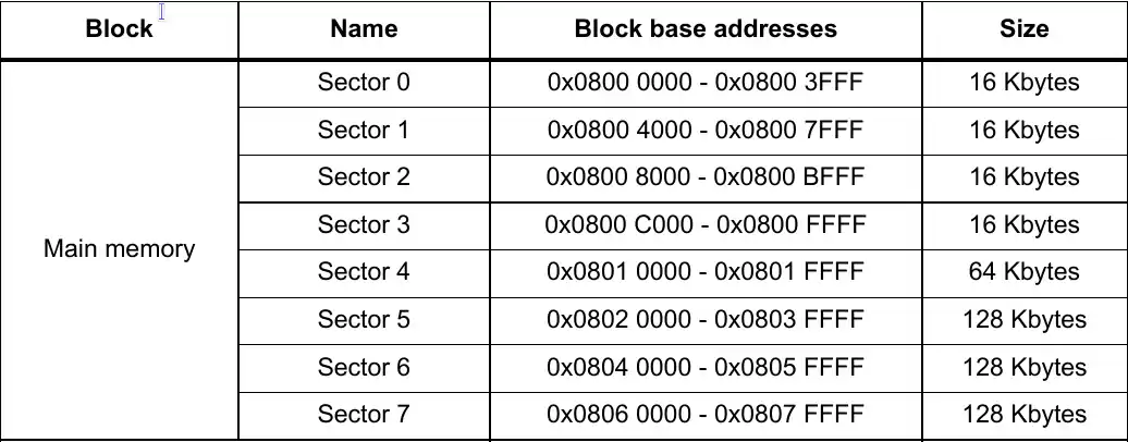
The image above shows the sector layout of the STM32F446RE. Because the sectors have different sizes, GetSector() compares the address with the start address of each sector. If your device has a different layout, change the sector addresses in GetSector() to match the datasheet of your device.
Some devices split the flash into two banks. In that case, check the reference manual for the sector addresses that apply to your bank configuration, and define them in GetSector() accordingly.
Sector-Based Flash Write Function
The function below erases the sectors that the data will occupy and then writes the data.
uint32_t Flash_Write_Data (uint32_t StartSectorAddress, uint32_t *Data, uint16_t numberofwords)
{

	static FLASH_EraseInitTypeDef EraseInitStruct;
	uint32_t SECTORError;
	int sofar=0;


	 /* Unlock the Flash to enable the flash control register access *************/
	  HAL_FLASH_Unlock();

	  /* Erase the user Flash area */

	  /* Get the number of sector to erase from 1st sector */

	  uint32_t StartSector = GetSector(StartSectorAddress);
	  uint32_t EndSectorAddress = StartSectorAddress + numberofwords*4;
	  uint32_t EndSector = GetSector(EndSectorAddress);

	  /* Fill EraseInit structure*/
	  EraseInitStruct.TypeErase     = FLASH_TYPEERASE_SECTORS;
	  EraseInitStruct.VoltageRange  = FLASH_VOLTAGE_RANGE_3;
	  EraseInitStruct.Sector        = StartSector;
	  EraseInitStruct.NbSectors     = (EndSector - StartSector) + 1;

	  /* Note: If an erase operation in Flash memory also concerns data in the data or instruction cache,
	     you have to make sure that these data are rewritten before they are accessed during code
	     execution. If this cannot be done safely, it is recommended to flush the caches by setting the
	     DCRST and ICRST bits in the FLASH_CR register. */
	  if (HAL_FLASHEx_Erase(&EraseInitStruct, &SECTORError) != HAL_OK)
	  {
		  HAL_FLASH_Lock();
		  return HAL_FLASH_GetError ();
	  }

	  /* Program the user Flash area word by word
	    (area defined by FLASH_USER_START_ADDR and FLASH_USER_END_ADDR) ***********/

	   while (sofar<numberofwords)
	   {
	     if (HAL_FLASH_Program(FLASH_TYPEPROGRAM_WORD, StartSectorAddress, Data[sofar]) == HAL_OK)
	     {
	    	 StartSectorAddress += 4;  // use StartSectorAddress += 2 for half word and 8 for double word
	    	 sofar++;
	     }
	     else
	     {
	       /* Error occurred while writing data in Flash memory*/
	    	 HAL_FLASH_Lock();
	    	 return HAL_FLASH_GetError ();
	     }
	   }

	  /* Lock the Flash to disable the flash control register access (recommended
	     to protect the FLASH memory against possible unwanted operation) *********/
	  HAL_FLASH_Lock();

	   return 0;
}The function follows the same steps as the page-based version, with sectors in place of pages. It unlocks the flash, works out the first and last sector that the data covers, erases those sectors, writes the data one 32-bit word at a time, and returns an error code if any step fails. The flash is locked again before the function returns.
Every call to this function erases the whole sector that it writes to. Values that need to be kept together should therefore be written in a single call, or stored in different sectors.
Sector-Based Flash Read Function
The read function is the same as in the page-based section, and it copies the requested number of words from flash into a buffer.
void Flash_Read_Data (uint32_t StartSectorAddress, uint32_t *RxBuf, uint16_t numberofwords)
{
	while (numberofwords--)
	{
		*RxBuf = *(__IO uint32_t *)StartSectorAddress;
		StartSectorAddress += 4;
		RxBuf++;
	}
}Sector-Based Flash Usage Example
The example below writes and reads the same four data types as the page-based example, using addresses in different sectors of the STM32F4.
char *data = "hello FLASH from ControllerTech\
			  This is a test to see how many words can we work with";

uint32_t data2[] = {0x1,0x2,0x3,0x4,0x5,0x6,0x7,0x8,0x9};

uint32_t Rx_Data[30];

char string[100];

int number = 123;

float val = 123.456;

float RxVal;

  Flash_Write_Data(0x08004100 , (uint32_t *)data2, 9);
  Flash_Read_Data(0x08004100 , Rx_Data, 9);


  int numofwords = (strlen(data)/4)+((strlen(data)%4)!=0);
  Flash_Write_Data(0x08008100 , (uint32_t *)data, numofwords);
  Flash_Read_Data(0x08008100 , Rx_Data, numofwords);
  Convert_To_Str(Rx_Data, string);


  Flash_Write_NUM(0x0800C100, number);
  RxVal = Flash_Read_NUM(0x0800C100);

  Flash_Write_NUM(0x0800D100, val);
RxVal = Flash_Read_NUM(0x0800D100);The example is organized in the following way:
- Variables and buffers:
datais the string to store,data2is an array of 32-bit integers, andRx_Datais the buffer that receives the data read back from flash. The variablesstring,number, andvalhold the converted string, the integer, and the float. - Integer array:
Flash_Write_Data()writes the 9 words ofdata2to flash, andFlash_Read_Data()reads the same 9 words back intoRx_Data. - String: The number of words is the string length divided by four and rounded up. The string is written and read back in the same way as the array, and
Convert_To_Str()turns the words into readable text. - Numbers:
Flash_Write_NUM()andFlash_Read_NUM()store and retrieve the integer and the float.
Sector-Based Flash Test Result
To check the result, open the memory viewer in your debugger and go to the addresses used in the example. The array data2 appears at 0x08004100 as the 32-bit values from 0x1 to 0x9. The string appears at 0x08008100 as groups of four bytes, with the readable text shown next to them. The integer and the float are stored at 0x0800C100 and 0x0800D100.
Video Tutorial: Sector-Based Flash Programming
The video below shows the complete sector-based procedure, including how to erase sectors, write the data, and read it back safely.
Conclusion
The internal flash gives an STM32 a simple place to keep settings, calibration values, and counters that must survive a power cycle. The HAL functions follow the same order on every device. The code unlocks the flash, erases the page or sector, writes the data one word at a time, and locks the flash again. Reading needs no unlock and only uses a pointer to the address.
The main difference between the families is the size of the block that an erase removes. On page-based devices such as the STM32F1, an erase clears a 1 KB page, and on sector-based devices such as the F4 and H7, it clears a sector that can be as large as 128 KB. For this reason, the data should be stored in an area that the firmware does not use, which is the last page on an F1 or a dedicated sector on an F4 or H7. Values that belong together should be written in a single call, because every call erases the block that it writes to.
The newer families need a little more care. On the STM32H5, G4, and L4, the error flags should be cleared right after the flash is unlocked, and the bank and page settings should be checked in the reference manual before the F1 and F4 code is reused. For data that must survive a power loss during a write, read the data back and compare it after every write, and keep a second copy in a different page or sector.
Internal flash is also the base for several other topics on this site. The STM32 custom bootloader series uses the same erase and write functions, starting with flash layout and application jump and ending with an OTA update. If the data only has to survive a reset or a low power mode, the backup registers of the STM32 internal RTC are a lighter option, and the STM32 low power modes tutorial explains why the SRAM is lost in Standby mode. When the internal flash is too small, the W25Q external flash series shows how to add an SPI flash chip, and the STM32 storage tutorials list the other storage options.
Download Project Here
Download the CubeMX project files and HAL source code — all tested on real hardware.
If you find this useful, you can support us with a Donation as well.
Browse More STM32 Flash Tutorials




Works well on STM32G474, thanks for the post.
Only one observation: Flash_Write_Data() if there is an HAL_FLASH_Program fails you return before locking the flash.
hey im using stm32wle5cb mcu , i can read the flash but when erasing to write earse operation it throughs error. is it because any protection or something need help
I was facing a similar error… I was able to write the first time and erase the sector… but I could only write to the FLASH again if I restarted the MCU (STM32H563RIT6). And I managed to solve this problem, obligatorily, by resetting the flags before erasing and writing.
Thanks, this was very helpful for the STM32H743…Do you have this for the STM32H563 micro as well??
It is not possible to write separate code for all the MCUs. Generally the H7 series follow the similar logic. You can test the same with H563 as well.
Hello Thanks for the tutorial.
Writing and reading is working for me, BUT when i then try to program again my MCU after a writing the prog/debugger can complete anymore the interaction.
I see error
Error message from debugger back end:
Error finishing flash operation
Error finishing flash operation
in order to be able to program/debug again i have to make a full erase and comment the writing function and reprogram.
I’m using a stm32F439 ZI.
Thanks again!
send email at [email protected]
Hey i have similar issue and tried to email but the email does ot exist
Thanks for the great tutorial. Helped me a lot. I noticed one minor bug in Flash_Read_Data. It should be
if (!(–numberofwords)) break;
instead of
if (!(numberofwords–)) break;
Otherwise there will be one additional loop run that might cause problems.
Thanks for this great tutorial. Helped me a lot. I noticed one minor bug in Flash_Read_Data. The line
if (!(numberofwords–)) break;
should be prefix decrement. So it should be changed to
if (!(–numberofwords)) break;
Otherwise there is one extra loop run.
I’m using your code from Github and I’m using STM32F103RC as well but the code didn’t work. I’m using the address 0x08005C10 and 0x08005D10. Write NUM function did not actually wrote anything into the flash (as I checked with the monitor it didn’t) and read NUM function only returns 0.
Hello Sir,
We are using STM32L432 and we are always getting error code as 128 that is FLASH_FLAG_MISERR. There are 2 changes done in our software.
EraseInitStruct does not have PageAddress element
EraseInitStruct.PageAddress = StartPage;
This was updated as
EraseInitStruct.Page = 127;
This error FLASH_FLAG_MISERR is appeared as part of the Page erase process. the following function output was 1.
status = FLASH_WaitForLastOperation((uint32_t)FLASH_TIMEOUT_VALUE);
The following error output was 128
error = (FLASH->SR & FLASH_FLAG_SR_ERRORS);
Do we have the example software for page erase for STM32L432 please?
Show less
Hello Sir,
We could write once and we are anot able to erase and update the last page. It looks like the flash is write protected. I meant we can compile and flash the chip. but we are not able erase the last page in our application software. How do we know the flash is write protected and How to clear the write protect before page erase? Could you please help us out?
I’m working on STM32H750 with FreeRTOS and code not work, the function HAL_FLASHEx_Erase error, the function run to FLASH_WaitForLastOperation and return HAL_TIMEOUT.
When i comment:
if (HAL_FLASHEx_Erase(&EraseInitStruct, &SECTORError) != HAL_OK)
{
return HAL_FLASH_GetError();
}
program work fine.
What the happen, I’m a little confused here. Do you have any suggest for me.
Hello,
I would like to know, Why a STM32 board binary code doesn’t run after I just flashed back to it of what I just red from the same board by using STM32 Cube Programmer?
Hi. It’s awesome tutorial. I have one question here.) What will happen to data in flash if power off and on
2) what will happen, if we flash again with read only function in main loop
Hi! Awesome tutorial, thanks for proper insight 🙂
Short question, why do you need to typecast again the pointer to array (uint32_t *) in the function Flash_Write_Data?
I am a little confused here 😀
Thanks!!
There is no need for that. I was testing with some strings (chars), so I might have done it because of that.
Hi,
I’m using STM32F429. I found your flash_sector_f4.c perfectly suited to my initial needs of storing binary data in a sector of flash. Thank you!
Now I’d like to be able to overwrite my running firmware with a new application after I’ve gotten it into RAM. I can’t use the built in bootloader. Is there an example of that anywhere? Thanks, Mike
You should check out this video series https://youtu.be/OkUQ3iMmiYQ
Hello,
I use STM32H725.
I need to implement Flash_Write_Data() at Low Level , without HAL .
Does anyone have low-level realization experience Write flash?
hello I have a problem
I can’t find the Flash_Write_NUM and Flash_Read_NUM functions
Para stm32F030C8, sua memória flash é páginas, mas quantas?
gracias
Hello
I have a question, and how can I get the free memory space I have left?
is there a HAL command?
Greetings from Colombia, your projects have helped me a lot
I’m work with the STM32F429 and stmcubeide. I’ve a error – conflicting types for ‘Flash_Write_Data’- when call a function uint32_t Flash_Write_Data (uint32_t StartSectorAddress, uint32_t *Data, uint16_t numberofwords)
{
int numofwords = (strlen(data)/4)+((strlen(data)%4)!=0);
Flash_Write_Data(0x08008100 , (uint32_t *)data, numofwords);
Flash_Read_Data(0x08008100 , Rx_Data, numofwords);
sprintf(teste_data2_char, “%d”, Rx_Data);
HAL_UART_Transmit(&huart1, (uint8_t *) teste_data2_char, strlen(teste_data2_char),500);
You are using older one.
Click the download button, it will take you to the github.
Download according to your controller
.
Hello sir Thank you very much for this code. I am working with the STM32G474RE. With your code I manage to write it but the delete is still not possible, what should I change or add? Thanks
which one did you used ?
hello dear
I used the “Flash Page Type”.
I do not know why I manage to write, but Erasing does not work, I always have to go through STM32 ST-LINK utility to be able to delete. could you please help me ?
The memory division in G4 is different, so you can’t use it directly.
It’s further divided into BANKS.
Maybe you can disable the banks and force the controller to use single BANK.
Also check the page size during debug.
unfortunately I’m only a beginner in this field, I don’t know how to force my controller to use the single Bank. Thank you once again for your time and your answers
Check your reference manual to know how to do that.
I am also working with STM32G474RE. Could you please share your insights or maybe even your code how you managed to write to the flash? Thank you so much!
hello sir .. i am new to this 32 bit this controller. i am writing code for stm32f207. while writing the flash ,controller gets stops in erase function, what is the problem , i am using base address is sector a10 and end address is sector11 .actually my flash data is 150 bytes only
If this FLASH_PAGE would be used with STM32L4 series where page size is 64bits, how big of a modification would this need? Thank you.
I also want to use the program for stm32L4 series please help as i got error while writing in similar fashion
Thanks to the Admin for sharing the Knowledge! Did someone manage to change the code for a STM32L4xx, in my case L452 (512x1Kb Pages)?
i write this code in keil MDK but has error for “(strlen(DATA_32)”
ERROR text:
(..\Src\FlASH_PAGE.c(109): error: #167: argument of type “uint32_t *” is incompatible with parameter of type “const char *”)
change the type inside strlen function
How can I use this code if my data is uint8_t?
I cant use the read function for ota purposes because in your function it only breaks when there is an empty cell. otherwise it runs until the end!!!!!!!!!!!!!!!!
therefore I added size parameter.
Hi!
I want to report some bug in FLASH_SECTOR. During saving I was getting a hardfault. The problem is that function HAL_FLASH_Program() expects the address of the variable to be saved. And you send a value DATA_32[sofar]. It should be the address: &DATA_32[sofar]. Great job again 🙂
Greetings!
F.Rak
In FLASH_SECTOR read function should be some other stop condition. Your stop condition is when you find 0xffffffff value in the array where you store read data. When this array is defined as global, the momory is alocated just for given array size. So when you want to read 2 bytes then you define array for 2 elements. In memory is alocated only 2 cells. After this 2 cells, other program data exist. So when you read in flash_sector_read more then 2 bytes you will plow the memory. This function should get one more parameter that is number of variables to read. Then one if statement it works much better.
Regards,
F.Rak
yeah ofcouse we can do that. The point in writing the 0xffffffff was that it will read the data of unknown length. But if you already know the length, then it should be easy just like you said.
When I write to the Flash I get memory protection and page alignment errors
memory protection might be turned on. Read your reference manual on how to remove it
Hi Sir.
How to find start page address ? In datasheet show page 127 address. I want to know another start page address.
They all are 1Kb in size. Just multiply 1024 to find the address.
For eg- 4*1024 = 4096 (0x1000) is the start address of page 4
127 *1024 = 130048 (0x1FC00) is the start address of page 127
Oh… Thanks. May I dump.
ex- 111*1024=113664(0x1bc00) right?
Thanks again.
yes. Make sure your flash size is 128 KB. Some bluepills have 64 KB
I copy your library and your code. Then string flash in 0x1FC00 that my bluepills have 128KB right. I plan to make my custom pcb with STM32F103C8T6 chip on it for prototype product. I think to be sure my code is write on it have 64KB for safe my product. Many THANKS.
I’m using Black Pill when i write to memory address it write and read quite well. But if i write in a loop for example i want to write to 0x08000400 and 0x08000400 the last written address is only stored in flash others are not stored why it’s happening? It’s urgent. Thank you
i didn’t understand the issue properly.. you have mentioned the same address twice in your comment
I’m sorry for my bad explanation here is the sample code..
for (int i = 0; i <= 5; i ++){
        if(i == 0){
           Flash_Write_Data(0x08006010, data);
                  Flash_Read_Data(0x08006010, Rx_Data);
                  println(Rx_Data);
        } if(i == 2){
           Flash_Write_Data(0x08006020, data1);
                  Flash_Read_Data(0x08006020, Rx_Data);
                  println(Rx_Data);
        } if(i == 3){
           Flash_Write_Data(0x08006030, data2);
                  Flash_Read_Data(0x08006030, Rx_Data);
                  println(Rx_Data);
        } if(i == 4){
           Flash_Write_Data(0x08006050, data3);
                  Flash_Read_Data(0x08006050, Rx_Data);
                  println(Rx_Data);
        }

        HAL_Delay(2000);
     }
After running this code data is stored only at this address 0x08006050 but during the iteration i can see that data is being stored by calling Read_Flash function and the output is this
14:10:19.482 -> Hello World
14:10:23.535 -> Hello World 1
14:10:25.564 -> Hello World 2
14:10:27.595 -> Hello World 3
But if i check the memory location using STM32CubeProgrammer i can only see last address data is stored in flash…
     for (int i = 0; i <= 8; i ++){
        if(i == 0){
           Flash_Write_Data(0x08006010, data);

        } if(i == 2){
           Flash_Write_Data(0x08006020, data1);

        } if(i == 3){
           Flash_Write_Data(0x08006030, data2);

        } if(i == 4){
           Flash_Write_Data(0x08006050, data3);
        }
        if(i ==5){
          Flash_Read_Data(0x08006010, Rx_Data);
                            println(Rx_Data);
        }if(i == 6){
                           Flash_Read_Data(0x08006020, Rx_Data);
                           println(Rx_Data);
        }if(i == 7){
          Flash_Read_Data(0x08006030, Rx_Data);
                           println(Rx_Data);
        }if(i == 8){
          Flash_Read_Data(0x08006050, Rx_Data);
                        println(Rx_Data);
        }

        HAL_Delay(2000);
     }
and the output is this
14:22:06.325 ->
14:22:08.329 ->
14:22:10.322 ->
14:22:12.354 -> Hello World 3
I don’t know what causing this..
you can not write data like that. You are trying to increase the address every few bytes. Check the page size of your controller in reference manual. Let’s assume it’s 1 KB. That means you can write once within that 1 KB size. If you try to write with an offset of 4 bytes, it will anyway erase the entire page and then write to that address.
I am using this concept to stm32f030f4 the value is uploaded to the flash memory address correctly and stored even though when the power is off but it does not reflect on the project kit when i reset the stm it works as per the coding logic it does not get the address value
thanks in advance
Thank you sir.
Hi,
i am using stm32H753 it has 2 memory banks BANK1 & BANK2 with 7 sectors each, and its a cortex-m7 controller,
i tried to use our program.it is not working
I checked the reference manual. Looks like there is a new memory system there. I need your project in order to modify it according to BANK type distribution. Contact me on that telegram group linked on the top right corner of website, or send a mail
Hi, I am using STM32H753 and i have same problem. How can i fix the problem? Can you help me please.
I will release an update for H7 series in a day or 2
Have you released the update for H7 series board? If yes, please share the link
Check the page again. It’s on the top
Thanks for the update. When i used the code for H7 series i got below error:
In function ‘Flash_Write_Data’:
../Drivers/STM32H7xx_HAL_Driver/Inc/Legacy/stm32_hal_legacy.h:425:39: error: ‘FLASH_VOLTAGE_RANGE_3’ undeclared (first use in this function);
I am using STM32H7A3 Nucleo board. I could not find out a definition for FLASH_VOLTAGE_RANGE_3 in my code. Please help me..
Try to comment out that line, and check.
Also make sure that the Sectors and Banks are defined properly in the flash_sector_h7.c file
Flash_Page.c file is written by you. Or It is in built HAL library file?
I wrote it, but took the reference from the examples provided by ST
Hello sir,
Iam using STM32L073Rz microcontrolller for flashing the data. But once we write the data in Particular address like 0X0802F000 iam not able to modify the string or numbers in the same address but we can flash another string in 0X0802F020 address. Please explain how to erase the previous flash data.
Iam trying to take external button as input after every press count value will be incremented and i am expecting to store the count value at any one address like 0X0802F000 after every increment count value stores at same address.
When use the board after power off also, count will be incremented from last value and it should be displayed on LCD or UART . Is it possible to do like that in Flash Programming.
I changed the GetPage function like this for STM32L073Rz is it correct
static uint32_t GetPage(uint32_t Address)
{
for (int indx=0; indx<512; indx++)
{
if((Address = (0x08000000 + 128*indx)))
{
return (0x08000000 + 128*indx);
}
}
return -1;
}
Please help to resolve the issue.
no it’s not correct. There is a lot confusion about the memory of the device that you have.
can u confirm the flash memory detail. does it have 1536 pages with each page being 128 bytes in size?
Yes sir,
Please verify in STM32L073RZ Referance Manual page no. 68/1034
RM0367 Reference manual
Hi there,
Is Bluepill board 64kb flash memory?
How do you use 128kb pages?
There is some confusion about 64 KB or 128 KB. But you can see in the video that it definitely uses the 128th page to write data, so I can say that it does have 128 KB of flash memory
Thanks for the reply and there is a confusion yes. But I thought it’s 64kb because it says 64kb in STM32CUBE IDE memory section on right bottom.