Home ▸ STM32 Tutorials ▸ USB Tutorials ▸
STM32 USB Mass Storage Class — SD Card as External Drive
This is Part 4 of the STM32 USB series. In Part 3, we used the HID class to emulate a USB mouse and keyboard. This time, we switch to the USB Mass Storage Class, which lets the STM32 behave as an external storage device — like a USB flash drive.
We will connect an SD card to the STM32 using the SDIO interface, and through the USB Mass Storage Class, that SD card will show up on your computer just like any removable drive. You can copy files to it, delete them, and manage them from the file explorer without writing any file system code on the STM32 side.
Before we get to the SD card, we will first use the STM32’s internal RAM as a temporary storage medium. This is a quick way to confirm the USB Mass Storage Class is working before we bring in the hardware.
The board used here is the STM32F446RE development board from WeAct Studio. This board has a built-in SD card slot that uses the SDIO interface, which makes it convenient for this project.
You can follow the other parts of this series here:
- Part 1: STM32 USB CDC: Virtual COM Port
- Part 2: STM32 USB HID Gamepad
- Part 3: STM32 USB HID Mouse and Keyboard
- Part 5: STM32 USB MSC with W25Q NOR Flash
- Part 6: STM32 USB Composite Device (CDC + HID)
- Part 7: STM32 USB HID Mouse and Keyboard Combined
- Part 8: STM32 USB Host MSC: Read & Write USB Flash Drive
- Part 9: STM32 USB HOST HID: Interface Mouse and Keyboard with STM32
How USB Mass Storage Works on STM32
Before writing any code, it helps to understand what is actually happening when you plug in an STM32 running the USB Mass Storage Class.
What the Mass Storage Class Does
The USB Mass Storage Class (MSC) makes the STM32 appear to the host computer as a storage device. The computer does not know or care whether the actual storage behind it is an SD card, a flash chip, or even RAM. It just sees a block device with a certain capacity.
When the STM32 is connected over USB, the host sends standard SCSI commands to it. These commands includes “tell me your capacity”, “read block 500”, or “write block 1200”. The STM32 translates those commands into actual reads and writes on whatever storage is attached. The USB Mass Storage Class handles all the USB protocol work, and we only need to implement the storage side.
This is why the same class works with RAM, SD cards, and SPI flash. We just swap out the read and write functions, and the rest stays the same.
The usbd_storage_if.c Bridge File
CubeMX generates a file called usbd_storage_if.c inside the USB_DEVICE folder. This file is the bridge between the USB stack and the actual storage. It contains six functions that we need to implement:
| Function | Purpose |
|---|---|
STORAGE_Init_FS | Initialize the storage medium |
STORAGE_GetCapacity_FS | Report total block count and block size |
STORAGE_IsReady_FS | Check if the storage is ready for a transfer |
STORAGE_IsWriteProtected_FS | Tell the host if writes are allowed |
STORAGE_Read_FS | Read one or more blocks from storage |
STORAGE_Write_FS | Write one or more blocks to storage |
All the USB protocol handling is done by the middleware. We only touch these six functions.
Why Sector Size Matters
Storage devices do not transfer data one byte at a time. They work in fixed-size chunks called sectors. For SD cards and most flash devices, the sector size is 512 bytes. Every time the computer requests a read or write, it asks for at least one full sector.
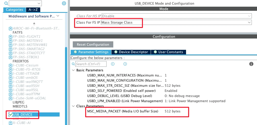
There is a parameter in CubeMX called media packet buffer size. This tells the USB Mass Storage Class how large the buffer should be to hold one sector during transfer. We need to set this to 512 bytes to match the SD card sector size. If this value is smaller, the transfer will not work correctly.
CubeMX Setup for USB MSC and SDIO
Let’s go through the full CubeMX configuration for this project.
USB Peripheral Configuration
The first thing we need to do is enable the USB peripheral. Locate and enable the USB Device (FS) or USB OTG FS peripheral, depending on your board. Make sure to choose Device Only mode, since we are using STM32 as a USB device connected to a PC. Once you do this, CubeMX automatically assigns PA11 and PA12 as the USB D− and D+ lines.

Note that all the parameters, low power mode, VBUS sensing, SOF output are disabled for a basic setup. We are using USB FS, this runs at Full Speed (12 Mbit/s).
Now go to the Middleware section and set the USB Device class to Mass Storage Class (MSC). Under the MSC parameters, set the media packet buffer size to 512.
A few parameters worth noting:
- Max number of configurations: Keep this at 1. Multiple configurations are used in composite device scenarios.
- Max number of interfaces: Keep this at 1 for now. In later tutorials we will add composite interfaces.
- USB self-powered: Set to enabled, since the board has its own power supply and does not draw operating power from the USB bus.
Clock Configuration
Next we need to set up is the clock. Enable the external high-speed oscillator (HSE) using the onboard 8 MHz crystal, and use the PLL to scale the system clock up to 180 MHz. We also need to make sure the USB peripheral receives exactly 48 MHz — go into the clock tree and adjust the PLL multipliers and dividers accordingly.

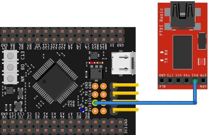
UART Configuration
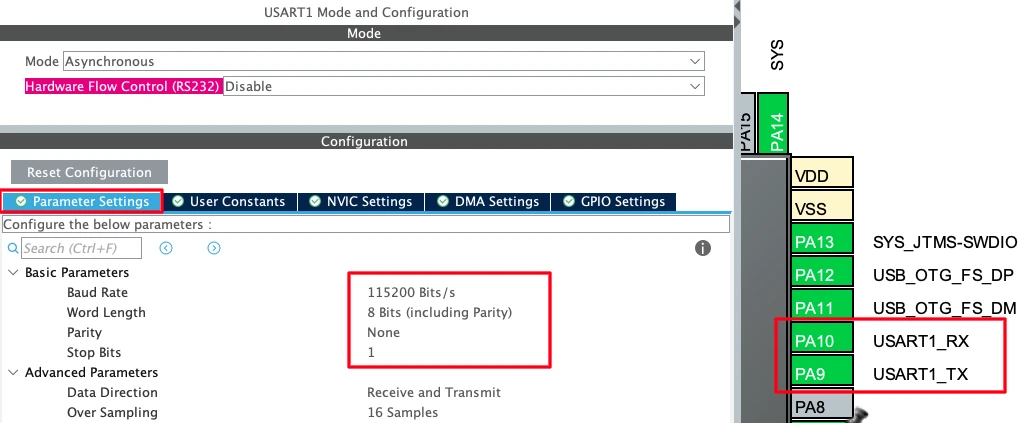
Enable UART1 in asynchronous mode with default settings. We will use this for logging via a USB-to-TTL adapter. The TX pin is PA9 and the RX pin is PA10.
Connect the STM32 TX pin to the RX pin of your USB-to-TTL module.
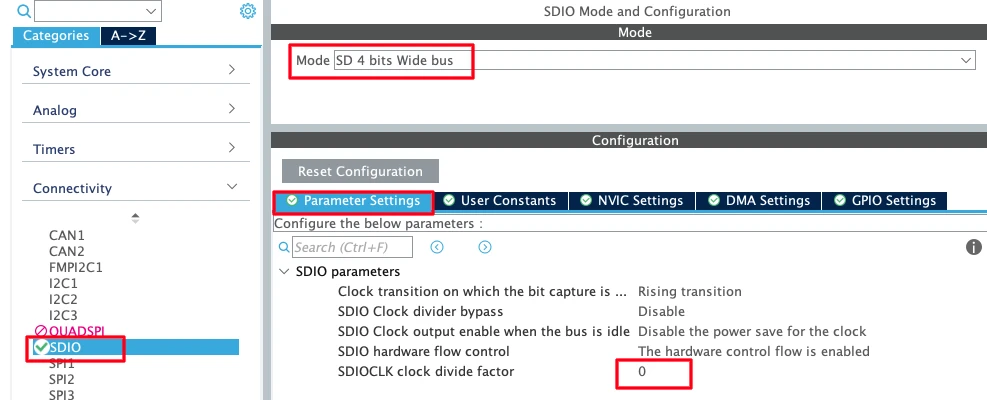
SDIO Peripheral Configuration
Go to the SDIO peripheral and enable it in 4-bit wide bus mode. This uses four data lines simultaneously, which gives four times the throughput compared to 1-bit mode.
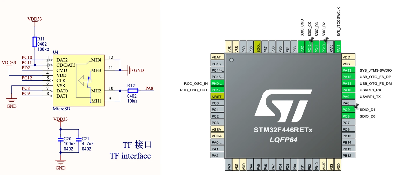
After enabling SDIO, CubeMX will assign default pins. You may need to reassign them to match the actual connections on your board. Check the schematic of the WeAct Studio board to confirm which pins are used for CMD, CLK, D0–D3, and the card detect line.
Clock Divider: The SDIO peripheral receives a 48 MHz input clock. The SD card clock is derived from this using a divider factor. With the divider set to 0, the formula gives:
SD_CLK = 48 MHz / (0 + 2) = 24 MHz24 MHz is the maximum we can provide with this setup. Leave the divider at 0 for best performance. If your SD card struggles at this speed, increase the divider to reduce the clock.
Also make sure to enable hardware flow control for SDIO. This prevents data overflow during transfers by signalling when the peripheral is ready.
Note:
When you look at the generated SDIO init code, you will notice the bus width starts in 1-bit mode during initialization and switches to 4-bit mode after. This is the correct sequence — the SD card must complete its handshake in 1-bit mode first. CubeMX handles this automatically, but if you are using a different setup, make sure this sequence is preserved.
STM32 USB Mass Storage Class: Code and Results
Now let’s go through the code step by step.
Setting up Serial Logging
Before touching anything USB-related, we verify the serial logging works. This is important because we will rely on it heavily to debug what is happening on the storage side.
Add a custom _write function to redirect printf output through UART1:
#include "stdio.h"

int _write(int fd, unsigned char *buf, int len) {
  if (fd == 1 || fd == 2) {                     // stdout or stderr ?
    HAL_UART_Transmit(&huart1, buf, len, 999);  // Print to the UART
  }
  return len;
}If you are using a different UART, change huart1 to the correct handle. This function is all that is needed, any printf call after this will send its output through the UART to your serial console.
RAM Storage Demo (Verifying the Class Works)
Before connecting the SD card, we use 100 KB of the STM32’s RAM as a fake storage device. This confirms the USB Mass Storage Class is working end-to-end.
Why do this? The STM32F446RE has 128 KB of RAM, and after code and stack, around 122 KB is free. Using RAM as storage lets us test the USB class without needing any hardware. If something is wrong with the USB setup, we find it here before adding the SD card complexity.
Open usbd_storage_if.c and make the following changes.
First, define the RAM buffer at the top of the file. All the data that the computer reads from or writes to our storage device will go through this buffer.
/* USER CODE BEGIN PRIVATE_VARIABLES */
uint8_t buffer[512 * 200];  // 100 KB RAM buffer
/* USER CODE END PRIVATE_VARIABLES */Now update STORAGE_GetCapacity_FS. This is called by the OS when it first connects to the device. We tell the host we have 200 blocks of 512 bytes each:
int8_t STORAGE_GetCapacity_FS(uint8_t lun, uint32_t *block_num, uint16_t *block_size)
{
    UNUSED(lun);
    *block_num  = 199;   // 200 blocks, but zero-indexed so max index is 199
    *block_size = 512;
    printf("Blocks=%lu Size=%u\r\n", *block_num, *block_size);
    return (USBD_OK);
}For STORAGE_IsReady_FS, RAM is always ready so we just return OK:
int8_t STORAGE_IsReady_FS(uint8_t lun)
{
    UNUSED(lun);
    return (USBD_OK);
}For STORAGE_Read_FS and STORAGE_Write_FS, we use memcpy to copy data between the RAM buffer and the USB data buffer:
int8_t STORAGE_Read_FS(uint8_t lun, uint8_t *buf, uint32_t blk_addr, uint16_t blk_len)
{
    UNUSED(lun);
    memcpy(buf, &buffer[blk_addr * 512], blk_len * 512);
    return (USBD_OK);
}

int8_t STORAGE_Write_FS(uint8_t lun, uint8_t *buf, uint32_t blk_addr, uint16_t blk_len)
{
    UNUSED(lun);
    memcpy(&buffer[blk_addr * 512], buf, blk_len * 512);
    return (USBD_OK);
}blk_addr * 512 converts the block number to a byte offset because each block is 512 bytes. blk_len * 512 converts the block count to the number of bytes to copy.
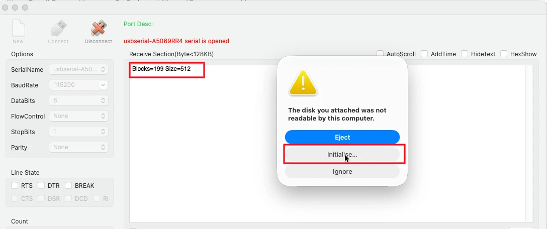
After flashing the project, connect the USB cable. The OS will ask you to format the drive since it is raw memory with no file system yet. Go ahead and format it as FAT32.
After formatting, the drive shows up in the file explorer with around 47 KB of usable space. Try copying a small file onto it and confirm it works.
Output
The image below shows the serial console output when the USB cable is connected, with the GetCapacity log visible, and the external drive appearing in the file explorer.
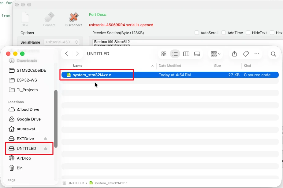
One important thing to note: if you disconnect and reconnect the USB without cutting power, the data stays in the RAM and the file is still visible. But if you power off the board completely, the RAM is wiped and the computer will ask you to format again. This is expected as RAM is volatile. This demo was just to confirm the class is working before we move to the SD card.
Switching to SD Card Storage
Now we replace the RAM buffer with the actual SD card.
Open usbd_storage_if.c. Comment out (or remove) the buffer array we defined earlier. Then declare the SD card handler as an external variable at the top of the user code section:
/* USER CODE BEGIN EXPORTED_VARIABLES */
// uint8_t buffer[512*200];   // RAM buffer — no longer needed
extern SD_HandleTypeDef hsd;
/* USER CODE END EXPORTED_VARIABLES */The hsd variable is initialized by the generated code in main.c. We just reference it here using extern.
Now update each function for the SD card.
STORAGE_Init_FS: The SDIO peripheral is already initialised by CubeMX-generated code. Nothing extra needed here.
STORAGE_GetCapacity_FS: Instead of hardcoding the block count, we read it directly from the SD card:
int8_t STORAGE_GetCapacity_FS(uint8_t lun, uint32_t *block_num, uint16_t *block_size)
{
    UNUSED(lun);
    HAL_SD_CardInfoTypeDef cardInfo;
    if (HAL_SD_GetCardInfo(&hsd, &cardInfo) != HAL_OK)
    {
        return USBD_FAIL;
    }
    *block_num  = cardInfo.LogBlockNbr - 1;
    *block_size = cardInfo.LogBlockSize;
    printf("Blocks=%lu Size=%u\r\n", *block_num, *block_size);
    return (USBD_OK);
}HAL_SD_GetCardInfo reads the card’s capacity registers and fills in the cardInfo structure. We subtract 1 from LogBlockNbr for the same zero-indexing reason as before.
STORAGE_IsReady_FS: Unlike RAM, the SD card can be busy during a transfer. We check the card state before returning ready:
int8_t STORAGE_IsReady_FS(uint8_t lun)
{
    UNUSED(lun);
    if (HAL_SD_GetCardState(&hsd) != HAL_SD_CARD_TRANSFER)
    {
        return USBD_FAIL;
    }
    return (USBD_OK);
}HAL_SD_CARD_TRANSFER means the card is idle and ready for a new request. Any other state means it is still busy.
STORAGE_Read_FS: We call HAL_SD_ReadBlocks and then wait for the transfer to complete:
int8_t STORAGE_Read_FS(uint8_t lun, uint8_t *buf, uint32_t blk_addr, uint16_t blk_len)
{
    UNUSED(lun);
    if (HAL_SD_ReadBlocks(&hsd, buf, blk_addr, blk_len, HAL_MAX_DELAY) != HAL_OK)
    {
        return USBD_FAIL;
    }
    while (HAL_SD_GetCardState(&hsd) != HAL_SD_CARD_TRANSFER) {}
    if (blk_addr % 1000 == 0)
    {
        printf("READ: ADDR=%lu LEN=%u\r\n", blk_addr, blk_len);
    }
    return (USBD_OK);
}The while loop is important. HAL_SD_ReadBlocks returns before the SD card has finished transferring data into the buffer. If we return from STORAGE_Read_FS too early, the USB stack will send incomplete data to the host. The loop holds us here until the card goes back to the transfer state, which means the data is fully in the buffer.
We only print every 1000 blocks to avoid flooding the serial console. Printing on every single call would add delays that could cause transfer timeouts.
STORAGE_Write_FS: It follows the same pattern as read function, but using HAL_SD_WriteBlocks:
int8_t STORAGE_Write_FS(uint8_t lun, uint8_t *buf, uint32_t blk_addr, uint16_t blk_len)
{
    UNUSED(lun);
    if (HAL_SD_WriteBlocks(&hsd, buf, blk_addr, blk_len, HAL_MAX_DELAY) != HAL_OK)
    {
        return USBD_FAIL;
    }
    while (HAL_SD_GetCardState(&hsd) != HAL_SD_CARD_TRANSFER) {}
    if (blk_addr % 1000 == 0)
    {
        printf("WRITE: ADDR=%lu LEN=%u\r\n", blk_addr, blk_len);
    }
    return (USBD_OK);
}Output
Before connecting the SD card to the STM32, make sure it is formatted in FAT32 File System. You can also copy a couple of test files onto it to verify them later. Then insert the card into the STM32 board, and connect the USB cable.
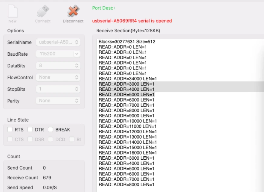
The image below shows the serial console immediately after connecting the USB cable — the GetCapacity log appears first, followed by multiple READ address logs as the OS scans the file system.
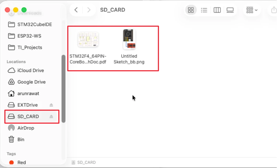
The image below shows the SD card appearing as an external drive in the file explorer, with the test files we copied earlier still intact.
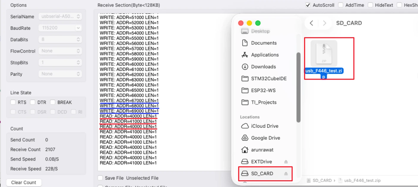
The image below shows WRITE logs appearing on the serial console while a 16 MB file is being copied to the SD card.
STM32 USB Mass Storage Class: SD Card as External Drive — Video Tutorial
This video walks through the complete setup of the STM32 USB Mass Storage Class with SDIO SD card on the STM32F446RE. We start with a RAM storage demo to verify the USB class is working, then switch to a real SD card that shows up as an external drive on your computer.
STM32 USB MSC — Frequently Asked Questions
Conclusion
That covers the full implementation of the STM32 USB Mass Storage Class with an SD card over SDIO. We started with a RAM storage demo to verify the USB class was working, which also showed that the same usbd_storage_if.c interface works with any storage medium. Once the class was confirmed working, switching to the SD card only required updating those six functions — everything else in the USB stack stayed the same.
The key things to remember: set the media packet buffer size to 512 to match the SD card sector size, always wait in the while loop after HAL_SD_ReadBlocks and HAL_SD_WriteBlocks before returning, and check the SD card state in STORAGE_IsReady_FS instead of always returning OK.
In the next part of this series, we will use an SPI flash chip (W25Q) as the storage medium with the same USB Mass Storage Class. If you run into any issues, drop a comment below.
Download STM32 USB Mass Storage SD Card Project
Open source CubeMX project files and HAL source code, tested on real hardware. Free to use — support the work if it helped you.
Browse More STM32 USB Tutorials
STM32 USB HID Gamepad: Configure STM32 as a Game Controller
STM32 as USB Mouse and Keyboard — HID Device Implementation
STM32 USB Mass Storage Class with W25Q NOR Flash: External Drive over SPI
STM32 USB Composite Class: CDC + HID Gamepad on One USB Port
STM32 USB HID: Combine Mouse and Keyboard on One Port

Subscribe
Login
0 Comments
Newest
