
Home ▸ STM32 Tutorials ▸ USB Tutorials ▸
Updated On: June 20, 2026
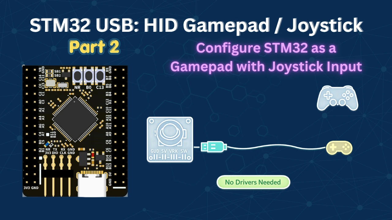
STM32 USB HID: Configure STM32 as a Gamepad with Joystick Input
This is the second tutorial in the STM32 USB series. In Part 1, we configured the STM32 as a USB CDC device, which let us send and receive data over USB just like a virtual serial port without using UART or any bridge chip.
In this tutorial, we are moving to the HID device class. We will configure the STM32 as a gamepad, connect an analog joystick module, read its X and Y axes over ADC with DMA, and send the data to the computer over USB. By the end, Windows, macOS, or any modern browser will see the STM32 as a fully functional game controller without installing any drivers.
You can follow the other parts of this series here:
- Part 1: STM32 USB CDC: Virtual COM Port
- Part 3: STM32 USB HID Mouse and Keyboard
- Part 4: STM32 USB MSC SD Card as External Drive
- Part 5: STM32 USB MSC with W25Q NOR Flash
- Part 6: STM32 USB Composite Device (CDC + HID)
- Part 7: STM32 USB Mouse and Keyboard Combined on one Port
- Part 8: STM32 USB Host: Mass Storage Class
STM32 USB HID: How It Works
Before we touch CubeMX, it helps to understand what HID actually is, why it does not need drivers, and what a report descriptor does. The code changes we make later will make a lot more sense once you understand this foundation.
What Is USB HID?
HID stands for Human Interface Device. It is a standard USB device class designed for devices that humans use to interact with a computer. Keyboards, mice, gamepads, joysticks, and drawing tablets all belong to the HID class.
The biggest advantage of HID is that every modern operating system already has a built-in HID driver. As soon as you plug in an HID device, the OS loads the driver automatically. You do not need to write or install anything on the PC side.
HID works on a simple model: the device sends data packets called reports to the host at regular intervals. Each report contains the current state of the device, such as axis positions, button states, and so on. The host reads these reports and maps them to the appropriate input events.
Standard HID vs Custom HID
In STM32CubeMX, you will see two HID options: Human Interface Device and Custom Human Interface Device.
The standard HID class covers devices the OS already understands, for example: gamepads, keyboards, mice, and similar. No driver writing required on the PC side.
The Custom HID class is for devices the OS does not know how to handle by default. In that case, you would also need to write a PC-side driver or application that knows how to interpret your custom reports. That is useful for specialized hardware, but it adds significant complexity.
Since gamepads are well-known devices, we will use the standard HID class throughout this tutorial.
Understanding the HID Report Descriptor
The HID report descriptor is a byte array that lives inside the firmware. It tells the host exactly what kind of data the device will send. The host reads this descriptor once during enumeration and uses it to understand every report that follows.
Think of it as a contract between the device and the host. The descriptor says: “I will send 3 bytes. The first byte is the X axis (0–255), the second byte is the Y axis (0–255), and the third byte has one bit for a button and seven bits of padding.” The host reads that, and from then on it knows how to decode every report.
CubeMX generates a mouse descriptor by default. We need to replace it with one that describes a gamepad. The next section covers exactly how to do that.
Wiring & Connections
The wiring for this project is straightforward. The joystick module has separate outputs for the X axis, Y axis, and a push button. Since the X and Y outputs are analog, we connect them to ADC-capable pins on the STM32.
Joystick Module Pinout
The joystick module I used has five pins: VCC, GND, VRx (X axis), VRy (Y axis), and SW (button switch). VRx and VRy output an analog voltage that varies with the joystick position. SW is a digital output that goes low when the joystick is pressed down.

Connecting the Joystick to STM32
Here are the connections I used with the weAct Studio F446 board:
| Joystick Pin | STM32 Pin | Function |
|---|---|---|
| VCC | 3.3V | Power |
| GND | GND | Ground |
| VRx | PA0 | ADC1 Channel 0 (X axis) |
| VRy | PA1 | ADC1 Channel 1 (Y axis) |
| SW | PA2 | GPIO Input with pull-up (Button) |

The button pin (PA2) is configured with an internal pull-up resistor. This means it reads high by default, and goes low when the button is pressed — which is how we detect the press in code.
CubeMX Setup, Code & Results
Now let us go through the complete implementation. We will start with a basic HID gamepad test, modify the report descriptor, and then add the actual joystick input over ADC with DMA.
CubeMX Configuration for HID
Start by creating a new project for the STM32F446. The basic setup — SWD debug, HSE crystal, PLL at 180 MHz, and USB OTG FS in Device Only mode — is the same as what we did in Part 1. If you need a refresher on those steps, check the USB CDC tutorial.
Once the USB peripheral is enabled, go to the Middleware section. Under USB Device, select the HID class (not Custom HID).

Under HID Parameters, there is one setting worth noting: HID_FS_BINTERVAL. This is set to 0x0A by default, which means the USB host will poll the device for new data every 10 milliseconds. That is perfectly adequate for a gamepad. We will keep it as is.
Before generating the code, go to the Device Descriptor tab.

Here I have changed the product name to STM32 Gamepad. So this is the name the computer will display when the device is connected. You can leave everything else at its defaults.
Next we need to make sure the USB peripheral receives exactly 48 MHz — go into the clock tree and adjust the PLL multipliers and dividers accordingly.

We will first test our basic driver, so this configuration is enough. When this works fine, we will configure the ADC and button in CubeMX.
Modifying the HID Report Descriptor
After importing the project in STM32CubeIDE, open usbd_hid.c. You will find it under the USB Device folder or under Middlewares → ST → STM32_USB_Device_Library → Class → HID → Core. Scroll down and you will see a descriptor array called HID_MOUSE_ReportDesc. CubeMX generates a mouse descriptor by default and we need to replace its contents with a gamepad descriptor.
Note:
Do not rename the function or the variable. Renaming them means updating references across multiple files. We are only changing the contents of the descriptor array.
Here is the complete gamepad descriptor we need:
__ALIGN_BEGIN static uint8_t HID_MOUSE_ReportDesc[HID_MOUSE_REPORT_DESC_SIZE] __ALIGN_END =
{
  0x05, 0x01,        /* Usage Page (Generic Desktop Ctrls)     */
  0x09, 0x05,        /* Usage (Gamepad)                        */
  0xA1, 0x01,        /* Collection (Application)               */
  // X and Y axes
  0x09, 0x30,        /*     Usage (X)                          */
  0x09, 0x31,        /*     Usage (Y)                          */
  0x15, 0x00,        /*     Logical Minimum (0)                */
  0x25, 0xFF,        /*     Logical Maximum (255)              */
  0x75, 0x08,        /*     Report Size (8 bits)               */
  0x95, 0x02,        /*     Report Count (2)                   */
  0x81, 0x02,        /*     Input (Data, Var, Abs)             */
  // Button
  0x05, 0x09,        /*     Usage Page (Button)                */
  0x19, 0x01,        /*     Usage Minimum (0x01)               */
  0x29, 0x01,        /*     Usage Maximum (0x01)               */
  0x15, 0x00,        /*     Logical Minimum (0)                */
  0x25, 0x01,        /*     Logical Maximum (1)                */
  0x95, 0x01,        /*     Report Count (1)                   */
  0x75, 0x01,        /*     Report Size (1 bit)                */
  0x81, 0x02,        /*     Input (Data, Var, Abs)             */
  // Padding (7 bits to complete the byte)
  0x95, 0x01,        /*     Report Count (1)                   */
  0x75, 0x07,        /*     Report Size (7 bits)               */
  0x81, 0x01,        /*     Input (Const, Array, Abs)          */
  0xC0               /* End Collection                         */
};Let me walk through the key parts.
Usage Page and Usage — We start with Usage Page set to Generic Desktop Controls, and Usage set to 0x05 which means Gamepad. This tells the host what kind of device this is.
X and Y axes — We declare Usage X (0x30) and Usage Y (0x31), set the logical range to 0–255 (8-bit values), Report Size to 8 bits, and Report Count to 2. The data type is set to Abs (absolute), because a joystick reports its actual position, not a relative change the way a mouse does.
Button — We switch to the Button usage page, set Usage Minimum and Maximum to 1 (because we have only one button), logical range 0–1 (button is either pressed 1, or not pressed 0), Report Size 1 bit, Report Count 1. Also absolute input.
Padding — The button only uses 1 bit. A USB HID report must be byte-aligned, so we pad the remaining 7 bits in that byte with constant (non-data) bits.
In total, the descriptor is 43 bytes. We need to update two values in usbd_hid.h to match:
#define HID_MOUSE_REPORT_DESC_SIZE    43U
#define HID_EPIN_SIZE 0x03UHID_EPIN_SIZE is set to 3 because our report is exactly 3 bytes: X axis, Y axis, and one button byte (1 bit button + 7 bits padding).
Testing Without a Physical Joystick
Before connecting the joystick, let us verify that the descriptor is correct and the computer recognizes the STM32 as a gamepad. In main.c, add the following at the top:
#include "usbd_hid.h"

extern USBD_HandleTypeDef hUsbDeviceFS;
uint8_t HID_Buffer[3] = {127, 127, 0};The buffer holds three bytes: X, Y, and button. We initialize X and Y to 127 (midpoint of 0–255) and button to 0.
Inside the while loop, we can temporarily make the values change on every loop iteration and send the report every 10 ms:
while (1)
{
HID_Buffer[0]++; // X increases
HID_Buffer[1]--; // Y decreases
USBD_HID_SendReport(&hUsbDeviceFS, HID_Buffer, 3);
HAL_Delay(10);
}Build and flash. On Windows, open Device Manager and look under Human Interface Devices — you should see STM32 Gamepad listed. On macOS, you can look under Settings → General → System Report → USB.

Open hardwaretester.com and go to the Gamepad section. After flashing and refreshing the page, the STM32 Gamepad should appear and both axes should be moving. This confirms the descriptor is correct and the HID pipeline is working end to end.

ADC + DMA Configuration in CubeMX
Now we add the actual joystick. Go back to CubeMX and configure the ADC.
Enable ADC1 with Channel 0 (PA0, X axis) and Channel 1 (PA1, Y axis).

Set the resolution to 8 bits — this matches our descriptor, which expects 0–255.
Note:
If you are using an STM32F103 (Blue Pill), ADC resolution is fixed at 12 bits. In that case, keep it at 12 bits but map the 0–4095 range down to 0–255 in code before filling the HID buffer.
Under DMA Settings, add a DMA request for ADC1. Set the mode to Circular and the data width to Byte (since we are using 8-bit resolution).

Back in the Parameter Settings, make the following changes:
- Increase the Clock Prescaler — this slows down the conversions so DMA transfers do not interfere with the HID send loop.
- Set Number of Conversions to 2.
- Enable Scan Conversion Mode (auto-enabled when you set 2 conversions).
- Enable Continuous Conversion Mode.
- Enable DMA Continuous Requests.
- Set End of Conversion Selection to End of All Conversions — this way the DMA interrupt only fires after both channels are done, not after each individual conversion.
Under the Rank configuration, set Rank 1 to Channel 0 (X axis) and Rank 2 to Channel 1 (Y axis). Increase the Sampling Time for both ranks to keep the conversion rate manageable.

Now configure the button. Set PA2 as GPIO Input. In the GPIO settings, enable the internal Pull-up resistor for PA2.

Reminder:
If CubeMX regenerates the project, it will overwrite usbd_hid.c. Copy the descriptor before regenerating and paste it back after. Also re-apply the HID_MOUSE_REPORT_DESC_SIZE and HID_EPIN_SIZE changes in usbd_hid.h.
Writing the Code
With the ADC and DMA configured, the code is straightforward. Here is the complete main.c with all the relevant user code sections filled in:
#include "usbd_hid.h"

extern USBD_HandleTypeDef hUsbDeviceFS;
uint8_t HID_Buffer[3] = {127, 127, 0};
uint8_t ADC_Val[2];
/* ADC DMA complete callback */
void HAL_ADC_ConvCpltCallback(ADC_HandleTypeDef *hadc)
{
HID_Buffer[0] = ADC_Val[0]; // X axis
HID_Buffer[1] = ADC_Val[1]; // Y axis
}
int main(void)
{
HAL_Init();
SystemClock_Config();
MX_GPIO_Init();
MX_DMA_Init();
MX_USB_DEVICE_Init();
MX_ADC1_Init();
/* Start ADC in DMA mode — 2 conversions */
HAL_ADC_Start_DMA(&hadc1, (uint32_t *)ADC_Val, 2);
while (1)
{
/* Read button — PA2 low means pressed */
if (HAL_GPIO_ReadPin(GPIOA, GPIO_PIN_2) == 0)
{
HID_Buffer[2] = 1;
}
else
{
HID_Buffer[2] = 0;
}
/* Send HID report every 10 ms */
USBD_HID_SendReport(&hUsbDeviceFS, HID_Buffer, 3);
HAL_Delay(10);
}
}Let me explain how it all fits together.
ADC_Val[2] is the buffer where DMA stores the converted values. ADC1 Channel 0 result goes into ADC_Val[0] and Channel 1 goes into ADC_Val[1]. Since DMA is in circular mode, it automatically restarts the conversions after both channels complete.
HAL_ADC_ConvCpltCallback fires after both channels are converted. Inside, we copy the ADC values directly into the HID buffer. HID_Buffer[0] is X, HID_Buffer[1] is Y.
In the while loop, we only handle the button. We check the input pin PA2. If it is low, the button is pressed and we put 1 in HID_Buffer[2]. Otherwise we put 0.
Then we call USBD_HID_SendReport with the 3-byte buffer and delay 10 ms, matching the polling interval.
Reminder:
HAL_ADC_Start_DMA expects a pointer to uint32_t, but ADC_Val is uint8_t. We typecast it to (uint32_t *) to avoid a compiler error. This is safe here because the DMA is configured for byte-width transfers.
Output
Gamepad Tester
The GIF below shows the gamepad tester at hardwaretester.com detecting the STM32 Gamepad with live X and Y axis movement from the joystick.

Playing a Game
The GIF below shows the STM32 Gamepad being used as a controller in a retro game emulator, with joystick left/right mapped to movement and the button mapped to jump.

STM32 USB HID Gamepad — Video Tutorial
This video walks through configuring the STM32 as a USB HID gamepad using STM32CubeMX. We modify the HID report descriptor, connect an analog joystick over ADC with DMA, and test the result on a gamepad tester website and a retro game emulator — all without any custom drivers.
STM32 USB HID Mouse/Keyboard — Frequently Asked Questions
Conclusion
In this tutorial, we configured the STM32 as a USB HID gamepad from scratch. We started by modifying the default mouse report descriptor to describe a gamepad with two analog axes and a button. Then we connected an analog joystick module, read its X and Y values over ADC with DMA, and sent the complete HID report to the computer every 10 milliseconds.
The result is a fully functional game controller that Windows, macOS, and modern browsers recognize automatically. We did not need any custom drivers or extra hardware, we just used a USB cable.
In the next part of this series, we will implement a keyboard and a mouse using the same HID device class (separately).
Download STM32 USB HID Gamepad Project
Open source CubeMX project files and HAL source code, tested on real hardware. Free to use — support the work if it helped you.
Browse More STM32 USB Tutorials
STM32 as USB Mouse and Keyboard — HID Device Implementation

STM32 USB Mass Storage Class: Use SD Card as External Drive

STM32 USB Mass Storage Class with W25Q NOR Flash: External Drive over SPI
STM32 USB Composite Class: CDC + HID Gamepad on One USB Port
STM32 USB HID: Combine Mouse and Keyboard on One Port

Subscribe
Login
0 Comments
Newest
