
Home ▸ STM32 Tutorials ▸ USB Tutorials ▸
Updated On: August 22, 2026
STM32 USB DFU Bootloader: Flash Firmware Over USB Without ST-Link
This is Part 11 of the STM32 USB series. In Part 10, we used the STM32 as a USB host to play WAV files through a USB speaker. In this part, we go back to USB device mode and use the built-in DFU bootloader to flash a project over USB, without touching the BOOT0 pin or using an ST-Link at all.
We are not writing a custom bootloader here. ST already ships one inside the system memory of every STM32 microcontroller. Our job is only to get the chip to jump into it on command. We do this by sending a string over USB CDC, and once the STM32 receives it, it resets itself and boots straight into DFU mode. From there, STM32CubeProgrammer takes over and flashes the new firmware over the same USB cable.
I am using the STM32F446 board from WeAct Studio for this project. This board does not have a built-in ST-Link, so it is a good example of where this technique actually pays off. Once the first firmware is flashed using an external programmer, every update after that goes through the USB port alone. I have also tested the same code on a Nucleo L496 board, and the steps stay the same for any STM32, as long as you look up the correct bootloader address for your chip.
You can follow the other parts of the USB series here:
- Part 1: STM32 USB CDC: Virtual COM Port
- Part 2: STM32 USB HID Gamepad
- Part 3: STM32 USB HID Mouse and Keyboard
- Part 4: STM32 USB MSC SD Card as External Drive
- Part 5: STM32 USB MSC with W25Q NOR Flash
- Part 6: STM32 USB Composite Device (CDC+HID)
- Part 7: STM32 USB HID Mouse and Keyboard Combined
- Part 8: STM32 USB Host MSC: Read & Write USB Flash Drive
- Part 9: STM32 USB Host HID: Read Keyboard and Mouse Data
- Part 10: STM32 USB Host Audio Class
STM32 USB DFU Bootloader — Video Tutorial
This video walks through triggering the built-in STM32 DFU bootloader from firmware using a USB CDC command and an RTC backup register. We configure CubeMX, write the bootloader jump code, and demonstrate a real firmware update on an STM32F446 board over USB alone — without an ST-Link.
How the STM32 USB DFU Bootloader Works
Every STM32 microcontroller ships with a DFU bootloader stored in its system memory. This memory is separate from the flash where our own application lives, and it cannot be erased or overwritten by us. The bootloader already knows how to configure the USB peripheral on its own, so we do not need to set up USB for DFU mode to work. We only need a way to jump into it.
The System Memory Bootloader
Normally, there are two common ways to enter this bootloader. The first is pulling the BOOT0 pin high and resetting the board, which forces the STM32 to boot from system memory instead of flash. The second is jumping into system memory ourselves from within the running application, which is what we are doing in this project.
The advantage of the second method is that we do not need physical access to the BOOT0 pin. This matters a lot on custom boards where BOOT0 is not broken out, or where there is no access to the reset button.
Finding the Bootloader Address in AN2606
Every STM32 series has its own system memory address, and we need to look this up before writing any code. ST documents this in the AN2606 application note, which covers the bootloader details for virtually every STM32 microcontroller.
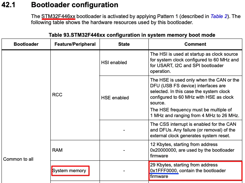
For the STM32F446, system memory starts at 0x1FFF0000. This is the same address used across most of the F4 series, including the F429 and the Nucleo L496 I tested this on earlier.
For the H745 or H755 series, system memory starts at 0x1FF00000, but the bootloader itself sits at 0x1FF09800.
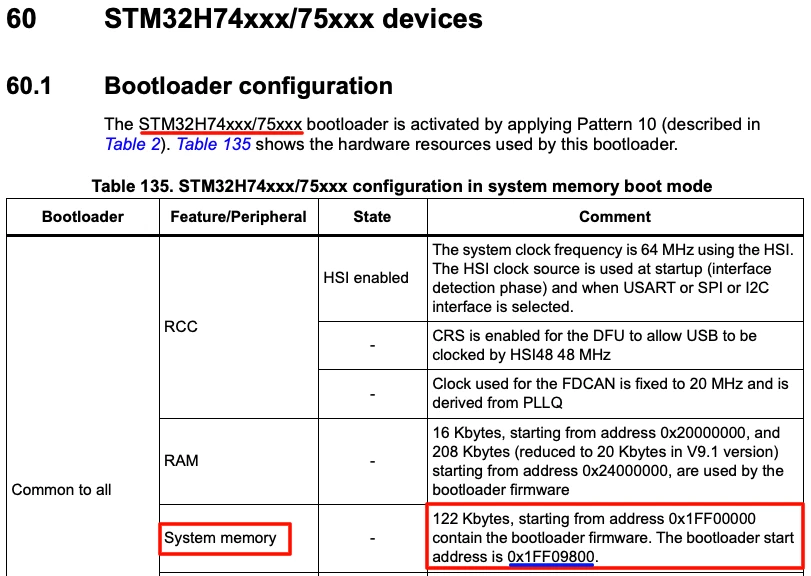
So the address is not the same across families, and you should confirm it for your own chip before moving forward. Everything else in this project stays the same regardless of which STM32 you use.
Jumping to the Bootloader from Firmware
On ARM Cortex-M microcontrollers, the first 4 bytes at the start of any memory region hold the initial stack pointer value, and the next 4 bytes hold the reset vector, which is the address of the first instruction to run. The bootloader region follows the same layout. So to jump into it, we read the reset vector from that offset, set the stack pointer, and branch to that address.
void jumpToBootloader(void)
{
    void (*SysMemBootJump)(void);

#define SYS_MEM_ADDRESS 0x1FFF0000U

    __disable_irq();

    SysTick->CTRL = 0;
    SysTick->LOAD = 0;
    SysTick->VAL  = 0;

    /* Remap system memory to 0x00000000 */
    __HAL_SYSCFG_REMAPMEMORY_SYSTEMFLASH();

    SysMemBootJump = (void (*)(void))(*((uint32_t *)(SYS_MEM_ADDRESS + 4)));
    __set_MSP(*(uint32_t *)SYS_MEM_ADDRESS);

    __enable_irq();

    SysMemBootJump();
    while(1);
}We disable interrupts first and reset the SysTick registers, since a stray SysTick interrupt right after the jump can crash the bootloader. We then remap system memory to address 0x00000000, because every STM32 always starts executing from that address after a reset. This remap step makes sure the bootloader is what actually runs next, instead of our own application.
There is one problem with calling this function directly from a running application. Cortex-M microcontrollers do not expect code to jump between two completely different runtime environments while still running. Peripherals, clocks, and the vector table are already set up for our own firmware, and jumping to the bootloader without a proper reset in between can leave the chip in an inconsistent state. The safe way to do this is to reset the board first, and jump into the bootloader immediately after that reset, before our own peripherals are initialized.
This means we need two things working together: a way to tell the STM32 “reset and go to DFU mode” from the computer, and a way for the firmware to remember, after that reset, that this is what it should do.
STM32 USB DFU: CubeMX Configuration
We need to configure the clock for both the CPU and the USB peripheral. We also need an output pin for the status LED and USB in CDC device mode, so that we can view the logs and send the boot command to the MCU.
Note that we do not need to configure the USB for DFU. Here I am configuring it for communication with the computer (CDC Mode).
USB CDC Configuration
The first thing we need to do is enable the USB peripheral. Locate and enable the USB Device (FS) or USB OTG FS peripheral, depending on your board. Make sure to choose Device Only mode, since we are using STM32 as a USB device connected to a PC. Once you do this, CubeMX automatically assigns PA11 and PA12 as the USB D− and D+ lines.

Now go to the Middleware section and set the USB Device class to Communication Device Class (CDC). Under the CDC parameters, I changed both the RX and TX buffer sizes from 2048 to 512 bytes, since we are not doing any high-throughput transfers.

Clock Configuration
Next we need to set up is the clock. Enable the external high-speed oscillator (HSE) using the onboard 8 MHz crystal, and use the PLL to scale the system clock up to 180 MHz. We also need to make sure the USB peripheral receives exactly 48 MHz — go into the clock tree and adjust the PLL multipliers and dividers accordingly.

LED Configuration
Finally, configure pin PB2 as a GPIO output for the onboard LED.

STM32 USB DFU: Code and Result
printf Routing Over USB CDC
To view log messages over the same USB CDC port, we route printf output through CDC_Transmit_FS:
int _write(int file, char *ptr, int len)
{
    while (CDC_Transmit_FS((uint8_t *)ptr, len) == USBD_BUSY)
    {
        HAL_Delay(1);
    }
    return len;
}The while loop is important here. CDC_Transmit_FS is non-blocking, so if the USB peripheral is still busy from a previous transfer, the function returns immediately without sending anything. The loop keeps retrying until the peripheral is free, ensuring the full data is transmitted before _write returns.
Triggering the Bootloader Jump
We use the RTC backup register to remember, across a reset, that the board should jump into DFU mode. The backup register keeps its value through a reset and even a power loss, similar to flash memory, but without the overhead of unlocking, writing, and erasing flash.
The jump command will be sent over the USB from the computer. Therefore, go to USB_DEVICE -> APP and open the usbd_cdc_if.c file. Inside it, there is a function CDC_Receive_FS, which is called whenever the computer send some data over the USB. Inside this function, we compare the incoming buffer against a fixed command string:
if (strcmp((char *)Buf, "ENTER DFU") == 0)
{
RTC->BKP0R = 0x1234;
NVIC_SystemReset();
}We write 0x1234 (Any Random Value) into backup register 0 and then reset the board. On the next boot, right at the start of main, before any other initialization runs, we check this register:
__HAL_RCC_PWR_CLK_ENABLE();
HAL_PWR_EnableBkUpAccess();
if (RTC->BKP0R == 0x1234)
{
RTC->BKP0R = 0;
jumpToBootloader();
}We enable the power controller clock and backup domain access first, since both are required before the backup register can be read. I have not enabled the RTC in CubeMX, hence we need to manually enable the clock and domain access here.
If the register holds our marker value, we clear it immediately, so a future reboot does not send the board into DFU mode again, and then call jumpToBootloader().
This check has to run before HAL_Init() and any peripheral setup, since we want to jump into the bootloader before our own application configures anything.
Full Code — main.c
Below is the complete main.c code.
#include "main.h"
#include "usb_device.h"
#include "usbd_cdc_if.h"
#include "stdio.h"
int _write(int file, char *ptr, int len)
{
    while (CDC_Transmit_FS((uint8_t *)ptr, len) == USBD_BUSY)
    {
        HAL_Delay(1);
    }
    return len;
}
void jumpToBootloader(void)
{
void (*SysMemBootJump)(void);
#define SYS_MEM_ADDRESS 0x1FFF0000U
__disable_irq();
SysTick->CTRL = 0;
SysTick->LOAD = 0;
SysTick->VAL = 0;
__HAL_SYSCFG_REMAPMEMORY_SYSTEMFLASH();
SysMemBootJump = (void (*)(void))(*((uint32_t *)(SYS_MEM_ADDRESS + 4)));
__set_MSP(*(uint32_t *)SYS_MEM_ADDRESS);
__enable_irq();
SysMemBootJump();
while(1);
}
int main(void)
{
__HAL_RCC_PWR_CLK_ENABLE();
HAL_PWR_EnableBkUpAccess();
if (RTC->BKP0R == 0x1234)
{
    RTC->BKP0R = 0;
    jumpToBootloader();
}
HAL_Init();
SystemClock_Config();
MX_GPIO_Init();
MX_USB_DEVICE_Init();
while (1)
{
HAL_GPIO_TogglePin(GPIOB, GPIO_PIN_7);
printf("Running Test 3..\r\n");
HAL_Delay(100);
}
}And inside usbd_cdc_if.c, add the command check in CDC_Receive_FS:
static int8_t CDC_Receive_FS(uint8_t* Buf, uint32_t *Len)
{
  /* USER CODE BEGIN 6 */
  USBD_CDC_SetRxBuffer(&hUsbDeviceFS, &Buf[0]);
  USBD_CDC_ReceivePacket(&hUsbDeviceFS);
  /* Add this part */
  if (strcmp((char*)Buf, "ENTER_DFU") == 0)
  {
	  RTC->BKP0R = 0x1234;
	  NVIC_SystemReset();
  }
  /* Till Here */
  return (USBD_OK);
  /* USER CODE END 6 */
}Output
The GIF below shows a serial terminal sending the “ENTER DFU” command to the STM32 over the USB CDC port, followed by STM32CubeProgrammer detecting the board as a USB device in DFU mode.

To flash the updated project, open STM32CubeProgrammer, connect to the detected USB device, browse to the project’s Debug folder, select the ELF file, enable the “Run after programming” option, and click Start Programming. The board resets automatically once flashing finishes, and the new firmware starts running right away.
I tested this by changing the LED blink rate between builds. The only connection to the board at this point is the USB cable, no external programmer involved. After sending “ENTER DFU” and flashing the updated build through STM32CubeProgrammer, the blink rate changed exactly as expected, confirming the whole flow works end to end on a board with no built-in ST-Link.
STM32 USB DFU Bootloader — FAQs
Conclusion
In this tutorial, we used the default DFU bootloader that already exists inside every STM32's system memory, without writing any bootloader code ourselves. We sent a command over USB CDC, used an RTC backup register to remember that a DFU jump was requested, and let the firmware handle the reset and the jump on its own. Once that piece was in place, flashing new firmware became a matter of sending one command and using STM32CubeProgrammer over the same USB cable.
This method is especially useful on custom boards like the STM32F446 board we used here, since there is no built-in ST-Link to fall back on. Once the first firmware was in place, we never had to touch the SWD pins again. The same USB port that prints our logs is also the one that flashes new firmware, and that is what makes this approach worth setting up. If you are using a different STM32, just check AN2606 for the correct bootloader address and the rest of the code stays the same.
Download STM32 USB DFU Bootloader Project
Open source CubeMX project files and HAL source code, tested on real hardware. Free to use — support the work if it helped you.
Browse More STM32 USB Tutorials
STM32 USB Composite Class: CDC + HID Gamepad on One USB Port
STM32 USB HID Device: Combine Mouse and Keyboard on One Port
STM32 USB Host MSC: Read & Write USB Flash Drive with FatFs and FreeRTOS
STM32 USB Host HID: Read Keyboard and Mouse Data with STM32
STM32 USB Host Audio Class: Play WAV Files from SD Card

Subscribe
Login
0 Comments
Newest

