Home ▸ STM32 Tutorials ▸
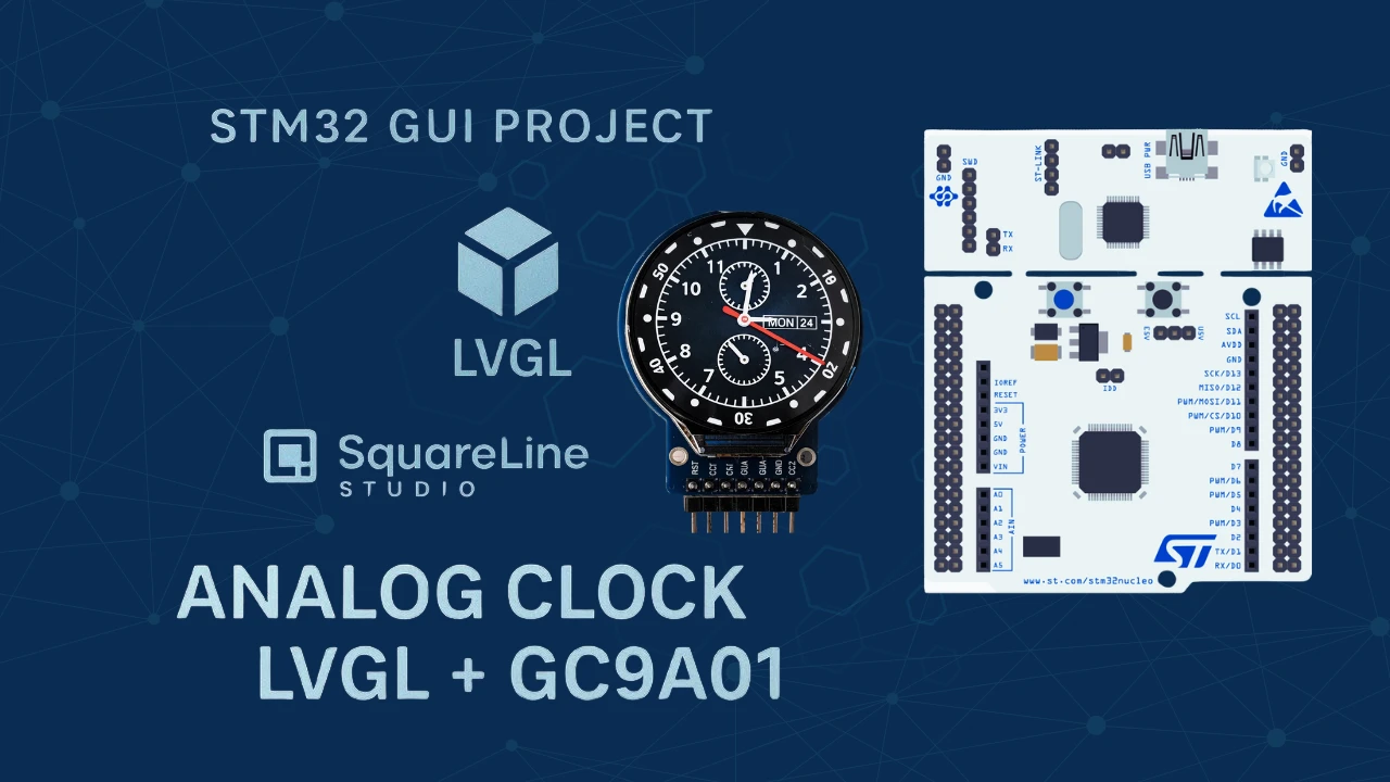
Analog Clock on GC9A01 Round Display with STM32, LVGL & RTC
Part 1 proved the pipeline: SPI wired, LVGL flushing, red ball bouncing on a 240×240 round display. Part 2 builds the application on top of that foundation, involving a real-time analog clock face with three image-based hands, each rotating from a precise pivot point and driven by the STM32 internal RTC.
This tutorial shows you how to design an analog clock UI in SquareLine Studio, configure the clock hand pivot points using GIMP, export the generated LVGL code into STM32CubeIDE, configure the STM32 RTC with a backup-register guard to persist time across resets, and write the updateClock() function that maps RTC seconds, minutes, and hours to the correct lv_img_set_angle() rotation values on screen. The complete CubeIDE project is available to download below.
This tutorial picks up directly from Part 1 — GC9A01 SPI & LVGL Integration. If you haven’t completed that yet, start there for the wiring, SPI/DMA CubeMX setup, LVGL installation, and the display flush callback. For RTC background, the STM32 Internal RTC tutorial is a useful pre-read. Browse the full STM32 LVGL tutorials collection for the broader series context.
What Is SquareLine Studio?
SquareLine Studio is a visual GUI design tool built specifically for LVGL. Instead of writing every widget position and style by hand in C, you drag and drop elements onto a canvas, configure properties in a sidebar, preview the layout in real time, and export ready-to-compile LVGL source files (ui.c, ui.h, and image assets). For embedded projects on tight timelines, it eliminates the back-and-forth of pixel-tweaking in code.
Why It Works Well with Round Displays
SquareLine Studio lets you set the canvas to any resolution and mark it as circular, so the 240×240 GC9A01 panel is treated as a circle in the preview — widgets outside the circular boundary are shown clipped exactly as they will render on the physical display. Image-based widgets (like clock hands) can be positioned and pivot-rotated with sub-pixel precision, which is essential for a clock face where a hand 1 pixel off-centre wobbles visibly.
Key Features
- Drag-and-drop widget placement — buttons, sliders, images, arcs, labels, and gauges placed without writing layout code.
- Real-time canvas preview — see rotation, alignment, and layering as they will appear on the target display.
- Automatic LVGL code export — generates clean
ui.c/ui.hfiles compatible with LVGL 9.2. - Pivot-point rotation — image widgets support a configurable pivot point for rotation, essential for clock hands that must rotate around the clock centre rather than the image corner.
- Multi-resolution support — design for any screen size including non-standard circular and square panels.
Project Requirements
| Component | Details |
|---|---|
| MCU board | WeAct Studio STM32H562RGT6 (≥ 512 KB Flash, 640 KB SRAM) |
| Display | 1.28-inch GC9A01 round TFT LCD, 240×240 px |
| IDE | STM32CubeIDE |
| Graphics library | LVGL 9.2 |
| UI design tool | SquareLine Studio |
Any STM32 board with ≥ 512 KB Flash, ≥ 20 KB free SRAM, and a hardware SPI peripheral will work. The LVGL flush pipeline from Part 1 must already be in place before starting this tutorial.
Design the Clock UI in SquareLine Studio
Create a New Project for GC9A01
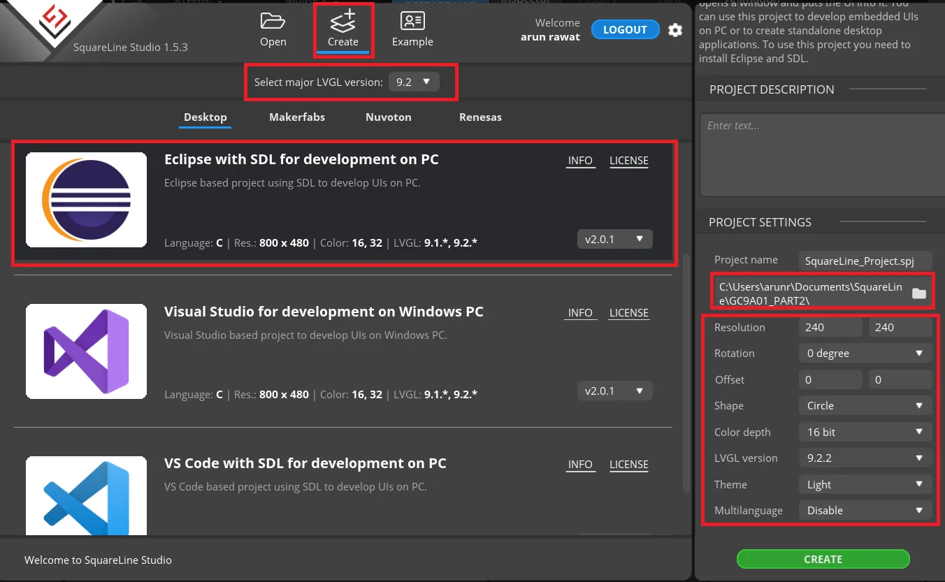
Open SquareLine Studio and create a new project:
- Framework: LVGL 9.2 (must match the LVGL version in your CubeIDE project from Part 1).
- Template: Eclipse with SDL for development on PC.
- Resolution: 240 × 240 px.
- Color depth: 16-bit (RGB565).
- Display shape: Circular.
- LVGL version: 9.2.2 (latest 9.2.x at time of writing).
Click Create. The canvas opens with a 240×240 circular preview area — anything outside the circle represents the non-visible screen border.
Import Clock Face and Hand Images
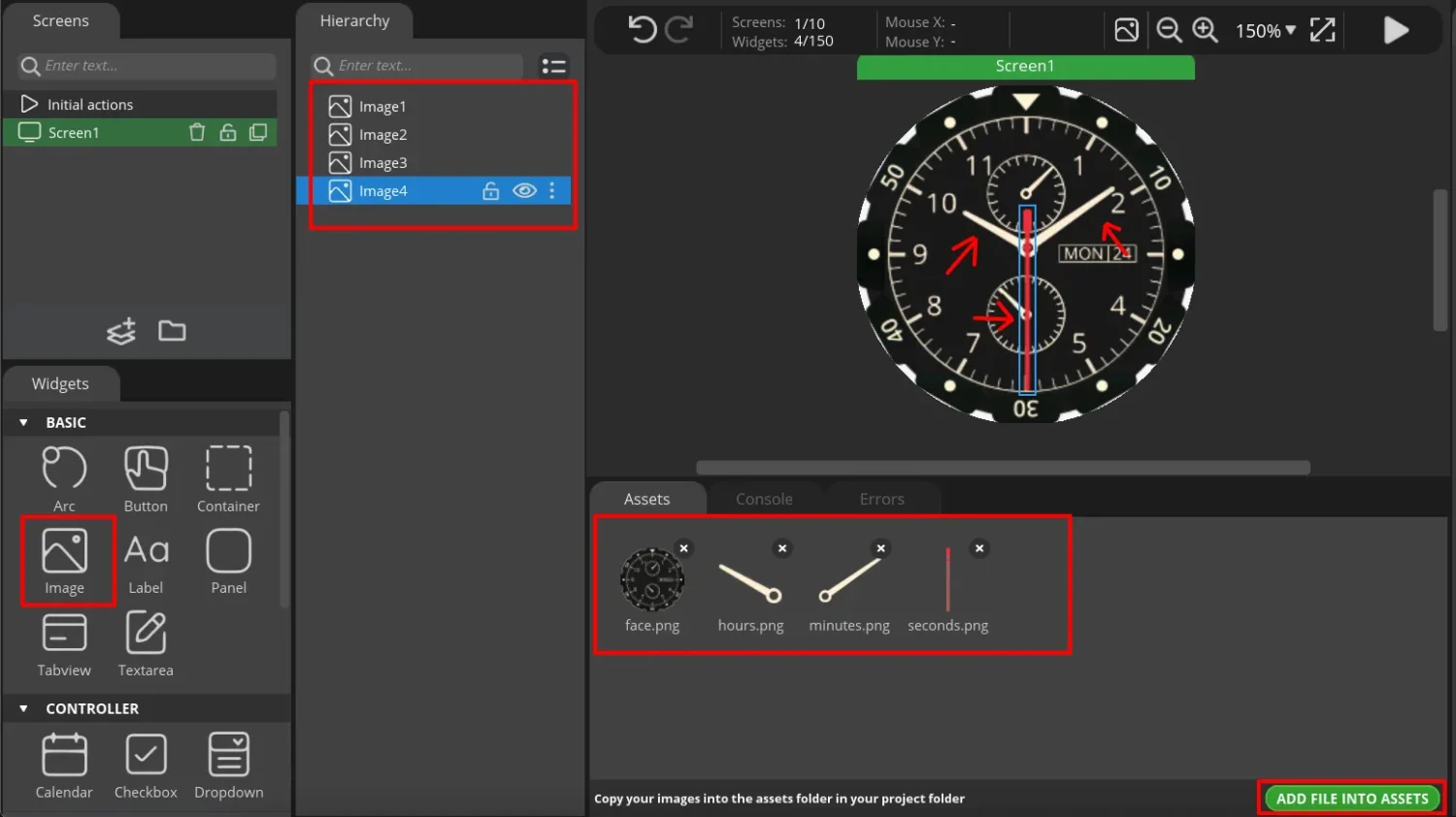
You need at minimum four PNG images:
- Clock face — the dial background with hour markers.
- Second hand — a thin needle image, tip pointing up at 12 o’clock.
- Minute hand — a wider needle image, tip pointing up at 12 o’clock.
- Hour hand — the shortest needle, tip pointing up at 12 o’clock.
Source these from any royalty-free graphics site. All images should have a transparent background (PNG with alpha channel).
In SquareLine Studio, go to Assets → Import and add all four images. Then drag each from Assets onto the canvas. Set each image widget to Image type, enable Anti-alias, and centre all hands on the clock face — they should all appear to overlap at the centre of the 240×240 canvas at this stage.
Find Pivot Coordinates with GIMP
Each clock hand image has a physical pivot point — the exact pixel on the image that corresponds to the centre of the clock (where the hand is pinned). For a second-hand image that is 240×240 px with the pivot at the base of the needle, this point is somewhere near the bottom-centre of the image, not the image corner.
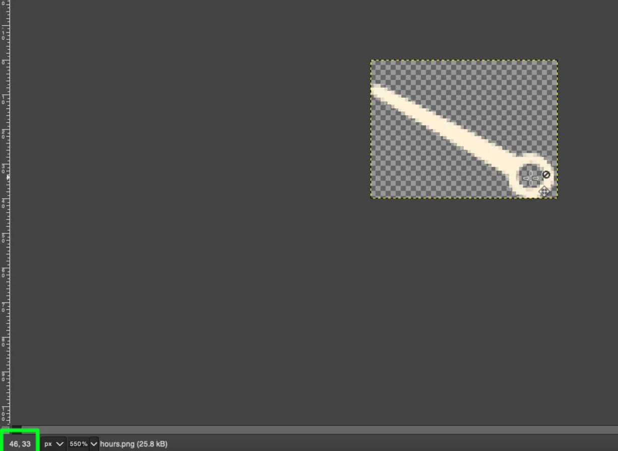
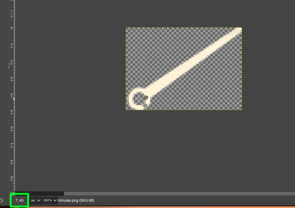
Open each hand image in GIMP. Hover the mouse over the point where the hand physically attaches to the clock centre. The x, y coordinates appear in the bottom-left status bar — note these down.
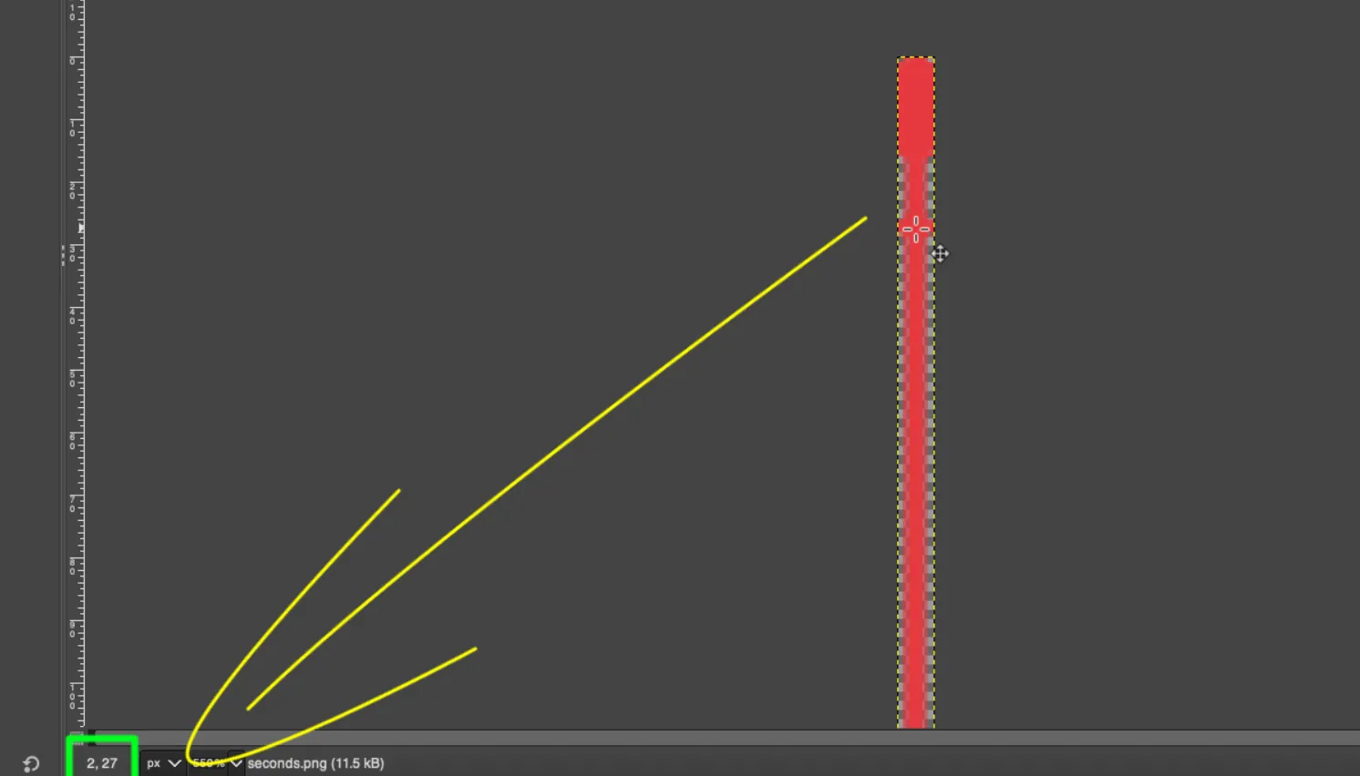
These coordinates are entered directly into SquareLine Studio’s Pivot X / Pivot Y fields for each hand image widget. Getting these values right is what makes each hand rotate around the correct centre point rather than spinning around its image corner.
Configure the Second Hand
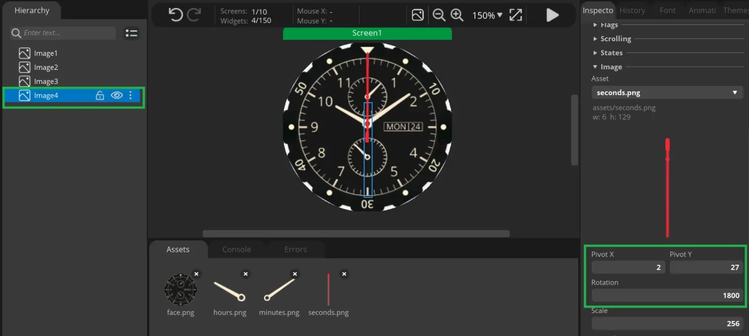
Select the second hand image widget on the canvas. In the properties panel:
- Set Pivot X / Pivot Y to the coordinates noted from GIMP.
- Test the rotation by manually entering rotation values in the Angle field — the hand should rotate around the fixed pivot point at the clock centre. If it wobbles off-centre, re-check the GIMP coordinates.
Rotation logic for the second hand:
- The second hand completes one full rotation (3600 LVGL units = 360°) in 60 seconds.
- Therefore it advances 60 LVGL units per second (
seconds × 60). - The +1800 offset aligns the hand to the 12 o’clock position at 0 seconds (the image’s “pointing up” orientation needs a 180° correction for this particular asset).
Configure the Minute Hand
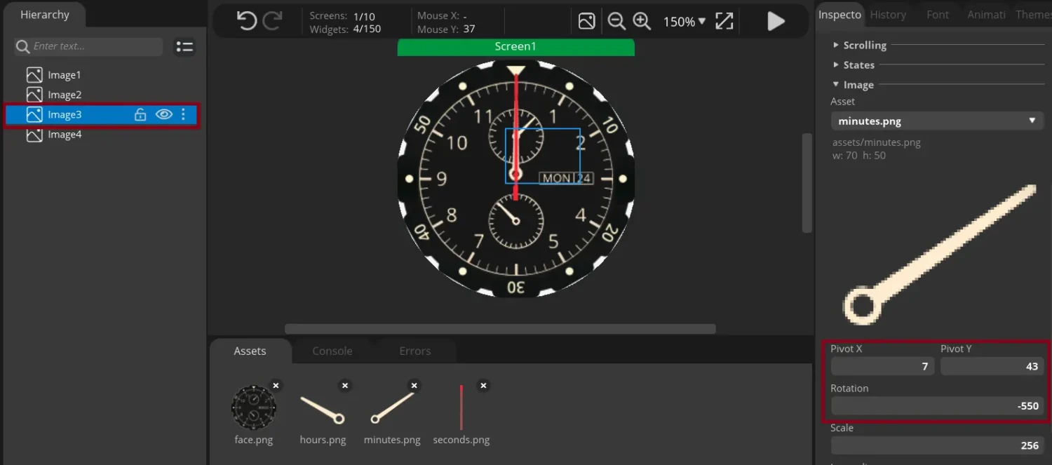
Select the minute hand widget. Set Pivot X / Pivot Y from the GIMP measurements for the minute hand image.
Rotation logic for the minute hand:
- The minute hand advances 60 LVGL units per minute (
minutes × 60). - The −550 offset aligns the hand to 12 o’clock at minute 0. It is negative because this particular hand image points slightly clockwise of 12, so a counter-clockwise correction is applied.
gTime.Secondsis added to the formula to make the minute hand move smoothly and continuously, rather than jumping instantaneously to the next minute mark every 60 seconds.
Configure the Hour Hand
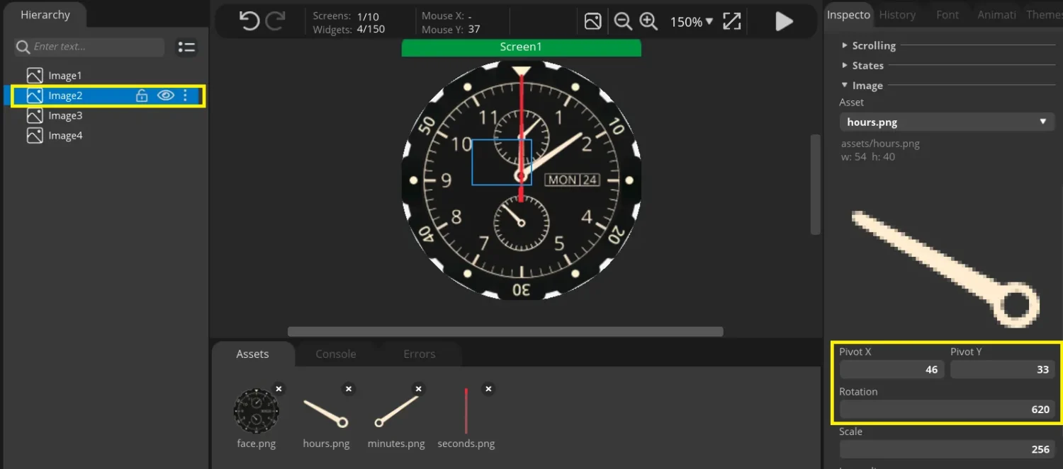
Select the hour hand widget. Set Pivot X / Pivot Y from the GIMP measurements for the hour hand image.
Rotation logic for the hour hand:
- There are 5 minute-divisions between each hour marker, and each division is 60 LVGL units. So one full hour sweep = 300 LVGL units (
hours × 300). - The +620 offset aligns the hand to 12 o’clock at hour 0.
gTime.Minutes × 5is added so the hour hand moves continuously across the hour sector rather than jumping from one hour mark to the next. Each minute contributes 5 LVGL units (300 units ÷ 60 minutes = 5 units/minute).
Export UI Files to STM32CubeIDE
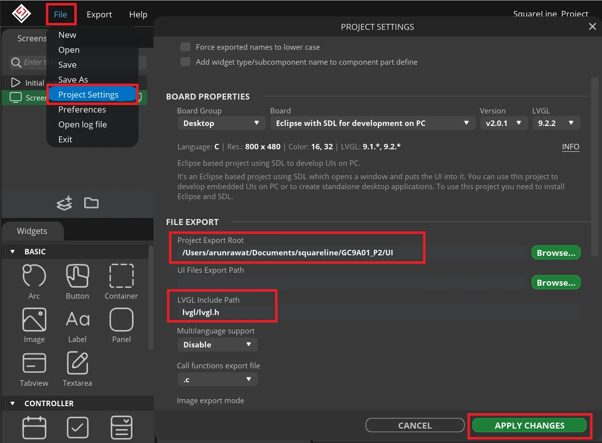
Open File → Project Settings in SquareLine Studio. Set:
- Export path: point this to a folder called
UIinside your STM32CubeIDE project directory. - LVGL include path:
lvgl/lvgl.h— this must match the include structure from Part 1.
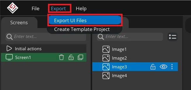
Click Export → Export UI Files. SquareLine Studio generates ui.c, ui.h, and any image asset C files into the UI folder.
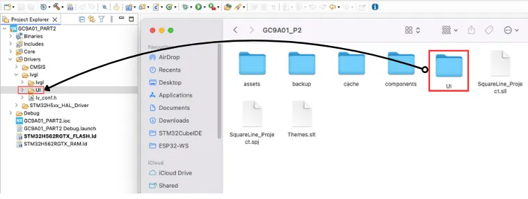
Copy the entire UI folder into your STM32CubeIDE project directory alongside the existing Src, Inc, and Drivers folders. Add the UI folder to the GCC compiler include paths in CubeIDE project properties (same steps as adding the LVGL path in Part 1).
STM32 RTC Configuration
SPI, DMA, and LVGL are already configured from Part 1. This section covers only what is new: the RTC peripheral.
RTC Clock Source — LSI at 32 kHz
The RTC needs a dedicated low-frequency clock source independent of the main system clock. Two options:
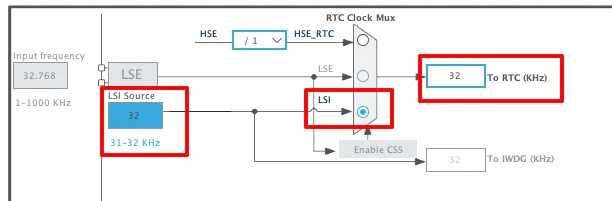
- LSI (Internal) — 32 kHz internal RC oscillator. No external components, but accuracy is ±5% typically. Used in this tutorial.
- LSE (External) — 32.768 kHz crystal connected to PC14/PC15. Better long-term accuracy. Use this if your board has a 32.768 kHz crystal fitted.
In CubeMX, enable the RTC peripheral and select LSI as the clock source under RCC.
RTC Parameters — 24-Hour Binary Format
Configure the RTC parameters:
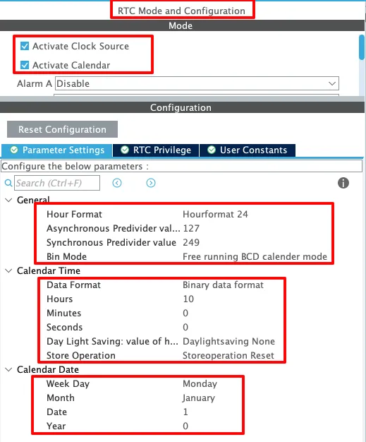
- Hour format: 24-hour.
- Data format: Binary (easier to work with in the rotation formulas than BCD).
- Assign placeholder time and date values in CubeMX — these will be overridden by the
setTime()function in code.
Prescaler Calculation for 1 Hz ck_spre
The RTC’s ck_spre signal needs to tick at exactly 1 Hz to drive real-time seconds. The prescaler divides the RTCCLK (32 kHz from LSI) down to 1 Hz according to the formula:
ck_spre = RTCCLK / ((PREDIV_A + 1) × (PREDIV_S + 1))With PREDIV_A = 127 and PREDIV_S = 249:
ck_spre = 32,000 / (128 × 250) = 32,000 / 32,000 = 1 HzSet these values in the RTC configuration panel. CubeMX may pre-fill them automatically when LSI is selected — verify before generating code.
HAL Code — RTC & Clock Update
Commenting Out Auto-Reset in MX_RTC_Init
CubeMX generates a MX_RTC_Init() function that sets the RTC time and date to the placeholder values you entered in the configurator. Without modification, every MCU reset calls this function and overwrites the running RTC time — the clock resets to 12:00:00 on every power cycle.
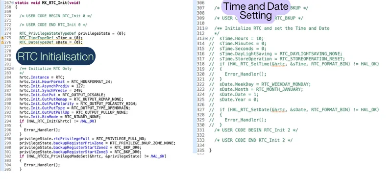
Open main.c, locate MX_RTC_Init(), and comment out the HAL_RTC_SetTime() block inside it. Do not remove the rest of the initialization — the RTC peripheral still needs to be configured. Only the time-writing lines should be commented out. The setTime() function below will handle this job instead, with a guard to prevent overwriting on subsequent resets.
setTime() — Setting Time Once After Reset
void setTime(int hour, int min, int sec)
{
    if (HAL_RTCEx_BKUPRead(&hrtc, RTC_BKP_DR0) != 0x4321)
    {
        RTC_TimeTypeDef sTime = {0};
        sTime.Hours   = hour;
        sTime.Minutes = min;
        sTime.Seconds = sec;
        sTime.DayLightSaving  = RTC_DAYLIGHTSAVING_NONE;
        sTime.StoreOperation  = RTC_STOREOPERATION_RESET;

        if (HAL_RTC_SetTime(&hrtc, &sTime, RTC_FORMAT_BIN) != HAL_OK)
        {
            Error_Handler();
        }

        HAL_RTCEx_BKUPWrite(&hrtc, RTC_BKP_DR0, 0x4321);
    }
}How the backup register guard works:
The STM32 has a set of battery-backed backup registers (RTC_BKP_DR0 through RTC_BKP_DR31) that retain their values as long as VBAT is supplied, even across full power cycles. The guard works like this:
- On the very first run,
RTC_BKP_DR0contains0x0000(factory default, not0x4321), so theifcondition is true —setTime()writes the specified hour/minute/second to the RTC and then writes the magic value0x4321intoRTC_BKP_DR0. - On every subsequent reset,
RTC_BKP_DR0already holds0x4321, so theifblock is skipped — the running RTC time is preserved.
0x4321 is an arbitrary sentinel value — any non-zero value that differs from the reset default will work, as long as you use it consistently.
updateClock() — Driving the Clock Hands
void updateClock(void)
{
    RTC_TimeTypeDef gTime;
    RTC_DateTypeDef gDate;

    HAL_RTC_GetTime(&hrtc, &gTime, RTC_FORMAT_BIN);
    HAL_RTC_GetDate(&hrtc, &gDate, RTC_FORMAT_BIN); // required to unlock shadow registers

    int16_t rotn;

    // Second hand
    rotn = (gTime.Seconds * 60) + 1800;
    lv_img_set_angle(ui_Image2, rotn);

    // Minute hand
    rotn = (gTime.Minutes * 60) - 550 + gTime.Seconds;
    lv_img_set_angle(ui_Image5, rotn);

    // Hour hand
    rotn = (gTime.Hours * 300) + 620 + (gTime.Minutes * 5);
    lv_img_set_angle(ui_Image4, rotn);
}Why must
HAL_RTC_GetDatealways be called? The STM32 RTC uses shadow registers — the time and date values are latched into readable registers only after a specific read sequence. HAL requires thatHAL_RTC_GetDate()be called afterHAL_RTC_GetTime()to complete the read sequence and unlock the registers for the next read. If you skipGetDate(), subsequentGetTime()calls may return stale values.
Second Hand Rotation Formula
rotn = (gTime.Seconds * 60) + 1800;
lv_img_set_angle(ui_Image2, rotn);LVGL’s lv_img_set_angle() takes rotation in tenths of a degree (3600 = 360°). One full revolution in 60 seconds means each second adds 3600 ÷ 60 = 60 units. The +1800 offset (180°) compensates for this clock asset’s image pointing downward at 0° — adding 180° flips it to point at 12.
| Seconds | Calculation | Angle (LVGL units) | Physical position |
|---|---|---|---|
| 0 | 0×60 + 1800 | 1800 | 12 o’clock |
| 15 | 15×60 + 1800 | 2700 | 3 o’clock |
| 30 | 30×60 + 1800 | 3600 | 6 o’clock |
| 45 | 45×60 + 1800 | 4500 | 9 o’clock |
Minute Hand Rotation Formula
rotn = (gTime.Minutes * 60) - 550 + gTime.Seconds;
lv_img_set_angle(ui_Image5, rotn);Each minute advances 60 LVGL units. The −550 offset corrects this asset’s resting orientation to 12 o’clock. Adding gTime.Seconds makes the minute hand move continuously — without it, the hand would sit static for 59 seconds then snap to the next minute mark instantly.
Hour Hand Rotation Formula
rotn = (gTime.Hours * 300) + 620 + (gTime.Minutes * 5);
lv_img_set_angle(ui_Image4, rotn);Each hour advances 300 LVGL units (30° × 10 tenths/degree = 300). The +620 offset aligns this asset to 12 o’clock. Adding gTime.Minutes × 5 makes the hour hand sweep smoothly across each hour sector (300 units ÷ 60 minutes = 5 units/minute) rather than jumping.
main() — Putting It All Together
#include "lv_port_disp.h"
#include "ui/ui.h"

int main(void)
{
    // ... HAL_Init, SystemClock_Config, MX_SPI1_Init,
    //     MX_GPIO_Init, MX_RTC_Init, MX_DMA_Init ...

    lv_init();
    lv_port_disp_init();   // initialize GC9A01 + connect to LVGL

    ui_init();             // initialize SquareLine Studio UI
    setTime(12, 12, 0);    // set RTC to 12:12:00 (first run only)

    while (1)
    {
        updateClock();         // read RTC and rotate clock hands
        lv_timer_handler();    // process LVGL events and flush display
        HAL_Delay(5);
    }
}Call order matters: lv_init() before lv_port_disp_init() before ui_init(). Calling ui_init() before lv_port_disp_init() will crash because LVGL’s display handle does not exist yet when the UI tries to attach widgets to it.
updateClock() is called on every while-loop iteration. With HAL_Delay(5), it runs approximately 200 times per second — far more than needed for a 1 Hz seconds hand, but the extra calls are harmless since the RTC value only changes once per second and lv_img_set_angle() is a fast in-memory operation.
Result

The clock displays the correct starting time of 12:12:00. The seconds hand ticks once per second, sweeping through the correct 6° arc per tick. The minute hand moves continuously and smoothly. The hour hand is correctly positioned between the 12 and 1 markers, reflecting the 12-minute elapsed time past the hour.
STM32 Analog Clock on GC9A01 — LVGL & SquareLine Studio Video Tutorial
Watch the complete walkthrough: designing the analog clock face in SquareLine Studio, finding pivot coordinates in GIMP, exporting UI files to STM32CubeIDE, configuring the STM32 RTC with backup-register time persistence, and running the real-time clock on the 1.28-inch GC9A01 round display.
FAQs — STM32 GC9A01 Analog Clock
Conclusion
The two-part GC9A01 series covers the full journey from raw SPI communication to a polished, real-time graphical clock application. Part 1 established the hardware and software pipeline: SPI wired, GC9A01 driver integrated, LVGL flushing pixel data to a 240×240 circular screen. Part 2 applied that infrastructure to a concrete application — an analog clock whose hands rotate smoothly, driven by the STM32 hardware RTC and positioned accurately using pivot points measured in GIMP and configured in SquareLine Studio.
The patterns here — SquareLine Studio for UI layout, RTC with backup-register persistence for real-time state, and lv_img_set_angle() for smooth animation — apply directly to other embedded UI projects: gauges, dials, animated indicators, and wearable displays. The round GC9A01 format just makes them look particularly good.
From here, the STM32 LVGL tutorial series covers more advanced topics: sending live ADC and UART data to a display, using the on-screen keyboard, and storing assets in QSPI Flash for projects where Flash space is constrained. Download the complete CubeIDE project below — it includes the SquareLine Studio exported UI files, the RTC configuration, and the full main.c.
Download STM32 GC9A01 Analog Clock Project Files (Part 2)
Complete CubeIDE project for STM32H562 — includes GC9A01 driver, LVGL 9.2, SquareLine Studio UI export (ui.c, ui.h, clock hand assets), RTC configuration, and main.c with setTime() and updateClock(). Free to download — support the work if it helped you.
Browse More STM32 Display Tutorials
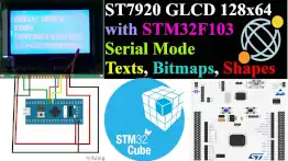
GLCD 128×64 ST7920 interfacing with STM32

Interface 16×2 LCD with STM32 (No I2C) — 4-bit Guide
Custom characters in LCD 1602 || STM32
Interface I2C-LCD1602 (AIP31068) with STM32
STM32 I2C LCD1602 with PCF8574 — HAL & CubeIDE Tutorial

Subscribe
Login
0 Comments
Newest
