
Home ▸ STM32 Tutorials ▸ Modbus ▸ TCP ▸
Updated On: October 18, 2026
STM32 Modbus TCP Server: Writing Coils (FC05 & FC15)
This is Part 5 in the STM32 Modbus TCP series using the LwIP Ethernet Library. In part 4 of this series, we added function codes 1 and 2 to our Modbus server, so the client was able to read the coils and discrete inputs.
In this part, we will handle the function codes 5 and 15, which are used by the client to write the coils. Function code 5 updates a single coil, and function code 15 updates multiple coils in a single request. This is also the last part in which we build the Modbus server itself, so after this tutorial, our STM32 will be able to handle every request a Modbus TCP client can send.
This is a continuation of the previous project, so I am not repeating the Ethernet or UART configuration here. If you have not gone through the earlier parts yet, go through them first. This time, there is a small CubeMX change, since we need to configure output pins to represent the coils connected to the server. On top of that, three files need to be replaced in the project: Modbus_Database.h, Modbus_Database.c, and Modbus_Parser.c.
This is the Part 5 in the STM32 Modbus TCP Series.
Table of contents
How Writing Coils Works
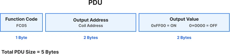
Function Code 5 (Write Single Coil) is used by the client to update the status of one coil at a time. The PDU of the request sent by the client consists of the address of the coil, followed by a 16-bit value. This value is not a plain 1 or 0. To set the coil, the client must send 0xFF00, and to reset it, it need to send 0x0000. Any other value is treated as invalid.
Function Code 15 (Write Multiple Coils) is used by the client to update multiple coils in a single request. Here, Instead of a 16-bit value per coil, the client packs the desired state of each coil into bits, and sends them together as a byte array. The PDU sent by the client consists of the starting address, quantity of the coils, byte count and the actual data in bytes.

In this tutorial, we will connect 5 LEDs to the server, representing the first 5 coils in our coil database. Whenever the client changes the state of these coils, the corresponding LED will turn on or off. The remaining 15 coils in the database can still be written by the client, but since no hardware is attached to them, their state will only be visible when read back.
Wiring the LEDs for the Coils
As I mentioned this is a continuation of the previous projects, so the potentiometer and the 5 switches from the earlier parts remain connected. Along with that, I have connected 5 LEDs, which represent 5 coils on the server. The image below shows the connection for this project.
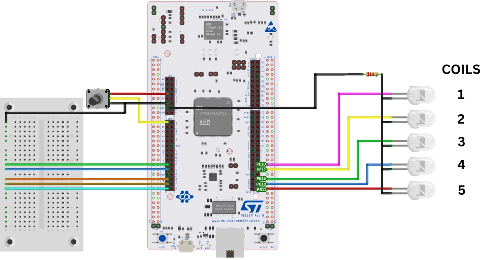
| Coil | GPIO Pin | Configuration |
|---|---|---|
| Coil 1 | PE10 | Output |
| Coil 2 | PE12 | Output |
| Coil 3 | PE15 | Output |
| Coil 4 | PB10 | Output |
| Coil 5 | PB11 | Output |
CubeMX Setup for the Coil Output Pins
The basic CubeMX configuration will remain the same as we covered in the previous tutorials. Therefore, the Ethernet, UART, ADC, and the 5 discrete input switches are already configured.
In this tutorial, we will configure 5 pins as output: PE10, PE12, PE15, PB10, and PB11. These are the pins where the LEDs will be connected to. Go to the System Core -> GPIO section, and give each of these pins a custom label, from Coil1 to Coil5, in the same order they are physically wired on the board.
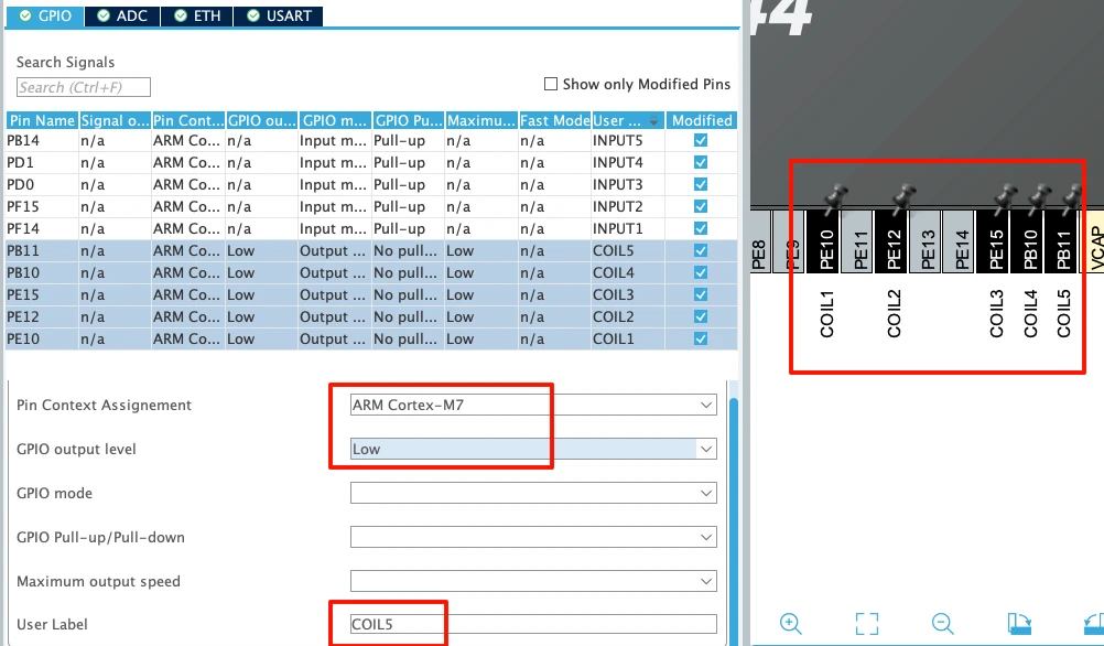
Since this is a dual core board and the Modbus TCP server runs only on the Cortex-M7 core, the GPIO context assignment for these pins should to be set to Cortex-M7. Also note that the GPIO Output Level is set Low so the Pins will be low by default.
Updating the LED Coils in Modbus_Database.c
There is no change inside Modbus_Database.h for this part. We still have the same 20 coils and 5 discrete inputs defined from the previous tutorial.
Inside Modbus_Database.c, the coil database is unchanged as well. The default states of the LEDs will depend on this database.
uint16_t MB_Coils[MB_COIL_COUNT] = {
        0x12, 0x34, 0x0D
};The only addition in this file is the MB_updateCoils function. It reads the current state of the first 5 coils and sets the corresponding LED pin high or low:
void MB_updateCoils(void)
{
    HAL_GPIO_WritePin(Coil1_GPIO_Port, Coil1_Pin, (MB_Coils[0] >> 0) & 0x01);
    HAL_GPIO_WritePin(Coil2_GPIO_Port, Coil2_Pin, (MB_Coils[0] >> 1) & 0x01);
    HAL_GPIO_WritePin(Coil3_GPIO_Port, Coil3_Pin, (MB_Coils[0] >> 2) & 0x01);
    HAL_GPIO_WritePin(Coil4_GPIO_Port, Coil4_Pin, (MB_Coils[0] >> 3) & 0x01);
    HAL_GPIO_WritePin(Coil5_GPIO_Port, Coil5_Pin, (MB_Coils[0] >> 4) & 0x01);
}Since there are 20 coils in total but only the first 5 are wired to LEDs, this function only works with the first byte of the coil database. The client can still update the remaining 15 coils normally, they simply will not be visible on the board.
Because this function is not declared inside Modbus_Database.h, it needs to be declared as an external function inside main.c. Then call it inside the infinite loop, right below MB_UpdateDiscreteInputs, so it runs every 500 milliseconds, the same as the other update functions:
extern void MB_updateCoils(void);

if ((HAL_GetTick() - prevTick) > 500)
{
    prevTick = HAL_GetTick();
    MB_UpdateInputRegisters();
    MB_UpdateDiscreteInputs();
    MB_updateCoils();
}Adding FC05 and FC15 Handlers in Modbus_Parser.c
MB_ProcessFunction Changes
Along with the already existing cases, 2 new cases are added inside the MB_ProcessFunction. One for writing a single coil and another for writing multiple coils:
case MB_FC_WRITE_SINGLE_COIL:
    return MB_FC05_WriteSingleCoil(pcb, req);

case MB_FC_WRITE_MULTI_COILS:
return MB_FC15_WriteMultipleCoils(pcb, req);Everything else in this function stays the same as part 4. If the client request any function code which is not defined here, the default case will be triggered and server will send an Illegal Function exception.
MB_FC05_WriteSingleCoil
This function handles the Function Code 5, which is used to write a single coil. The PDU of a Write Single Coil request consists of one byte for the function code, two bytes for the coil address, and two bytes for the value.
The function starts by extracting the address and value variables:
address = ((uint16_t)req->Data[0] << 8) | req->Data[1];
value = ((uint16_t)req->Data[2] << 8) | req->Data[3];Then it performs the address check. Since we have already defined the database for 20 coils, the client cannot request to update a coil beyond that range:
if(address >= MB_COIL_COUNT)
return MB_SendException(pcb, req, MB_EX_ILLEGAL_DATA_ADDRESS);If the address is valid, it extracts which byte of the database holds this coil, and which bit inside that byte represents it:
uint16_t sourceByte = address / 8;
uint8_t sourceBit = address % 8;Then it checks the value received from the client. If it is 0xFF00, the corresponding bit in the database is set. Otherwise, If it is 0x0000, the bit is cleared. Any other value results in an Illegal Data Value exception, since the standard does not define any other meaning for this field:
if(value == 0xFF00)
{
MB_Coils[sourceByte] |= (1 << sourceBit);
}
else if(value == 0x0000)
{
MB_Coils[sourceByte] &= ~(1 << sourceBit);
}
else
{
return MB_SendException(pcb, req, MB_EX_ILLEGAL_DATA_VALUE);
}Once the coil has been updated, the response is prepared. The MBAP header remains the same as the other functions we covered previously. The length field is fixed at 6 bytes, which accounts for the unit ID, function code, address, and value fields:
tx[4] = 0;
tx[5] = 6;The PDU for the response consists of the function code, the address, and the value. Basically, the same command is sent back to the client:
tx[7] = MB_FC_WRITE_SINGLE_COIL;
tx[8] = address >> 8;
tx[9] = address;
tx[10] = value >> 8;
tx[11] = value;Below is the complete function.
static err_t MB_FC05_WriteSingleCoil(struct tcp_pcb *pcb, MB_Request_t *req)
{
uint16_t address;
uint16_t value;
uint8_t tx[12];
address = ((uint16_t)req->Data[0] << 8) | req->Data[1];
value   = ((uint16_t)req->Data[2] << 8) | req->Data[3];
if(address >= MB_COIL_COUNT)
    return MB_SendException(pcb, req, MB_EX_ILLEGAL_DATA_ADDRESS);
uint16_t sourceByte = address / 8;
uint8_t sourceBit   = address % 8;
if(value == 0xFF00)
{
    MB_Coils[sourceByte] |= (1 << sourceBit);
}
else if(value == 0x0000)
{
    MB_Coils[sourceByte] &= ~(1 << sourceBit);
}
else
{
    return MB_SendException(pcb, req, MB_EX_ILLEGAL_DATA_VALUE);
}
tx[0] = req->TransactionID >> 8;
tx[1] = req->TransactionID;
tx[2] = 0;
tx[3] = 0;
tx[4] = 0;
tx[5] = 6;
tx[6] = req->UnitID;
tx[7] = MB_FC_WRITE_SINGLE_COIL;
tx[8] = address >> 8;
tx[9] = address;
tx[10] = value >> 8;
tx[11] = value;
if(tcp_write(pcb, tx, sizeof(tx), TCP_WRITE_FLAG_COPY) != ERR_OK)
return ERR_MEM;
tcp_output(pcb);
return ERR_OK;
}One thing worth remembering here: the client does not set a coil by sending a plain 1. It has to send the full 16-bit value 0xFF00 to set the coil, and 0x0000 to reset it.
MB_FC15_WriteMultipleCoils
This function handles the Function Code 15, which is used to write a multiple coils at once. The PDU dent by the client for this consists of the function code, the starting address, the quantity of coils to write, a byte count, and finally the actual coil data.
The function starts by extracting the starting address, the quantity, and the byte count:
startAddr = ((uint16_t)req->Data[0] << 8) | req->Data[1];
quantity = ((uint16_t)req->Data[2] << 8) | req->Data[3];
byteCount = req->Data[4];Then it start making few checks. The first check makes sure the quantity is not 0, and it does not exceed 1968. This limit is defined by the Modbus standard:
if((quantity == 0) || (quantity > 1968))
return MB_SendException(pcb, req, MB_EX_ILLEGAL_DATA_VALUE);Since coil data is packed into bits, even a small number of coils needs a full byte to represent them. So the next check makes sure the byte count sent by the client actually matches the quantity of coils being requested:
expectedByteCount = (quantity + 7) / 8;
if(byteCount != expectedByteCount)
return MB_SendException(pcb, req, MB_EX_ILLEGAL_DATA_VALUE);The last check is for the address range. It makes sure the client does not try to write beyond the 20 coils we have defined:
if((startAddr + quantity) > MB_COIL_COUNT)
return MB_SendException(pcb, req, MB_EX_ILLEGAL_DATA_ADDRESS);Once all three checks pass, the function extracts the bit data and writes it to the coils database. The for loops once for every coil the client wants to write. On each run, it first calculates which byte and bit of the incoming request data hold the value for that coil:
uint8_t sourceByte = i / 8;
uint8_t sourceBit = i % 8;
uint8_t state = (req->Data[5 + sourceByte] >> sourceBit) & 0x01;It then calculates which byte and bit of the coil database need to be updated, based on the starting address and the current loop count:
uint16_t coilAddress = startAddr + i;
uint16_t coilByte = coilAddress / 8;
uint8_t coilBit = coilAddress % 8;Depending on the value of the state variable, the corresponding bit in the database is either set or cleared:
if(state)
MB_Coils[coilByte] |= (1 << coilBit);
else
MB_Coils[coilByte] &= ~(1 << coilBit);This is very similar to how coils were read in part 4, except here the direction is reversed. Instead of copying bits from the database into the response, we are copying bits from the request into the database.
Once every coil has been updated, we need to prepare the response. The MBAP header for the response will remain the same as we covered in the previous case. The length field is still fixed at 6 bytes. The PDU is also same as the previous case, it consists of the function code, the starting address, and the quantity of coils written:
tx[7] = MB_FC_WRITE_MULTI_COILS;
tx[8] = startAddr >> 8;
tx[9] = startAddr;
tx[10] = quantity >> 8;
tx[11] = quantity;Below is the complete function.
static err_t MB_FC15_WriteMultipleCoils(struct tcp_pcb *pcb, MB_Request_t *req)
{
uint16_t startAddr;
uint16_t quantity;
uint8_t byteCount;
uint8_t expectedByteCount;
uint16_t i;
uint8_t tx[12];
startAddr = ((uint16_t)req->Data[0] << 8) | req->Data[1];
quantity = ((uint16_t)req->Data[2] << 8) | req->Data[3];
byteCount = req->Data[4];
if((quantity == 0) || (quantity > 1968))
return MB_SendException(pcb, req, MB_EX_ILLEGAL_DATA_VALUE);
expectedByteCount = (quantity + 7) / 8;
if(byteCount != expectedByteCount)
return MB_SendException(pcb, req, MB_EX_ILLEGAL_DATA_VALUE);
if((startAddr + quantity) > MB_COIL_COUNT)
return MB_SendException(pcb, req, MB_EX_ILLEGAL_DATA_ADDRESS);
for(i = 0; i < quantity; i++)
{
uint8_t sourceByte = i / 8;
uint8_t sourceBit = i % 8;
uint8_t state = (req->Data[5 + sourceByte] >> sourceBit) & 0x01;
uint16_t coilAddress = startAddr + i;
uint16_t coilByte = coilAddress / 8;
uint8_t coilBit = coilAddress % 8;
if(state)
MB_Coils[coilByte] |= (1 << coilBit);
else
MB_Coils[coilByte] &= ~(1 << coilBit);
}
tx[0] = req->TransactionID >> 8;
tx[1] = req->TransactionID;
tx[2] = 0;
tx[3] = 0;
tx[4] = 0;
tx[5] = 6;
tx[6] = req->UnitID;
tx[7] = MB_FC_WRITE_MULTI_COILS;

tx[8] = startAddr >> 8;
tx[9] = startAddr;

tx[10] = quantity >> 8;
tx[11] = quantity;
if(tcp_write(pcb, tx, sizeof(tx), TCP_WRITE_FLAG_COPY) != ERR_OK)
return ERR_MEM;
tcp_output(pcb);
return ERR_OK;
}That covers everything new in Modbus_Parser.c. We do not need to modify anything in the main.c, other than the one line already mentioned above, calling MB_updateCoils inside the loop.
Testing Server with Simply Modbus TCP Client
After flashing the project, open the serial terminal on the ST-Link virtual COM port at 115200 baud. Also open Simply Modbus TCP Client and connect to the server’s IP address on port 502.
Reading the coils first
Before writing anything, we will request 10 coils starting from coil 1.
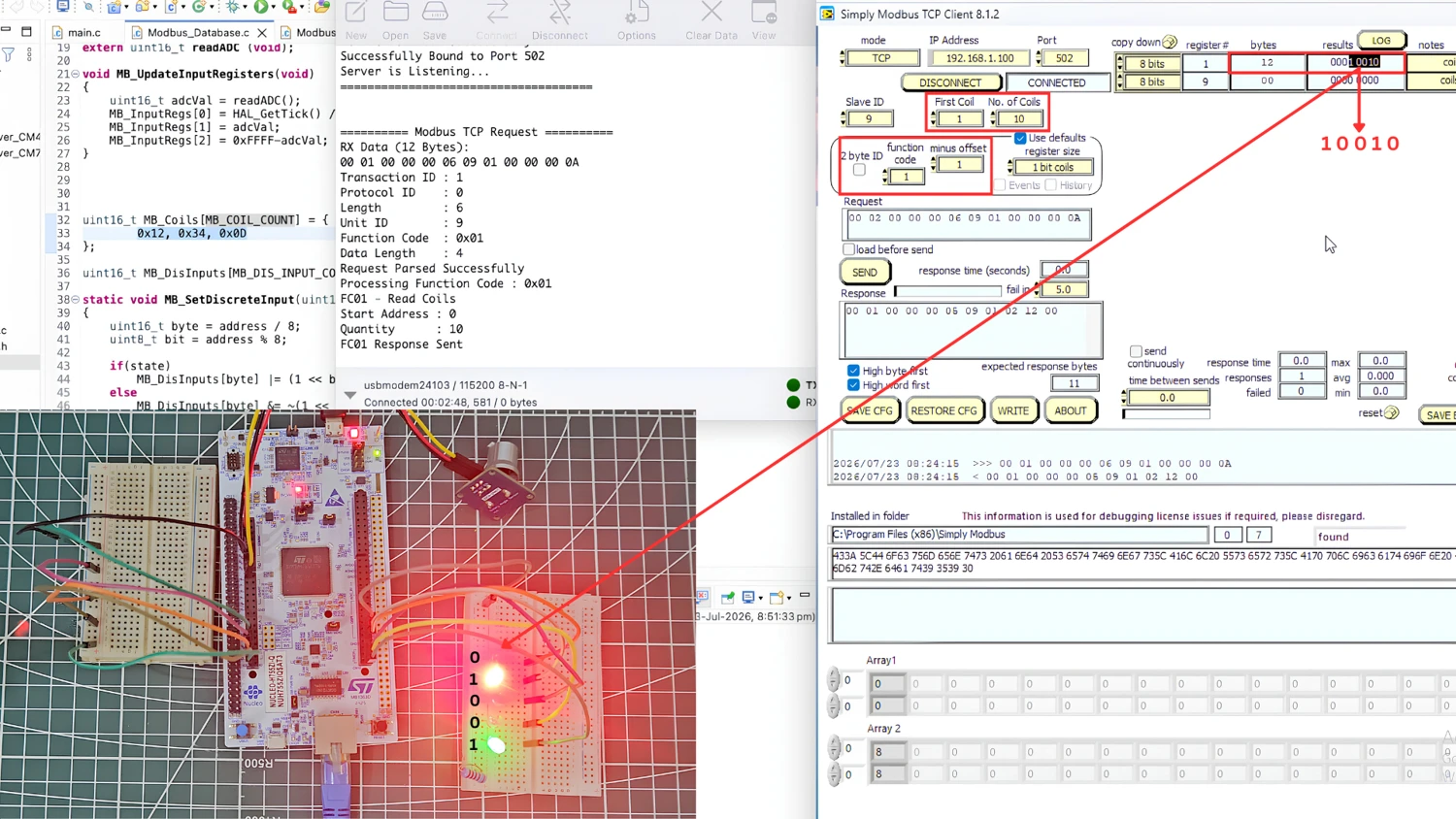
You can see the data returned by the server matches the coils data in the database we defined. Also note that the first 5 bits are also reflected on the five LEDs connected to the board.
Writing a single coil (FC05)
We will use the function code 5 to write Coil 1, which currently read 0. To set this coil, the client sends the value 0xFF00. Once the request is sent, the first LED turns on, confirming that the coil has been set.
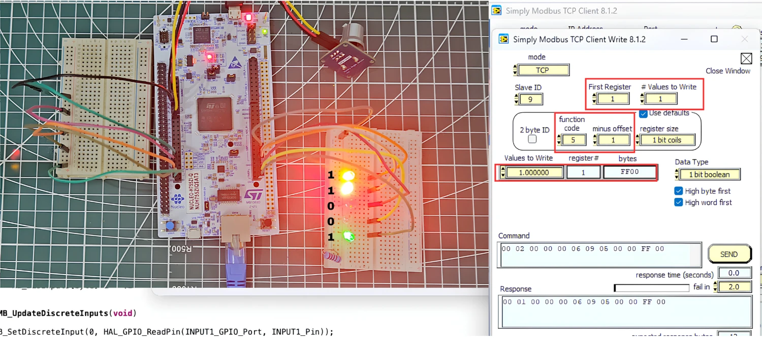
Let’s try the same for Coil 3 as well. It is also reset by default, so we will set it to 1.
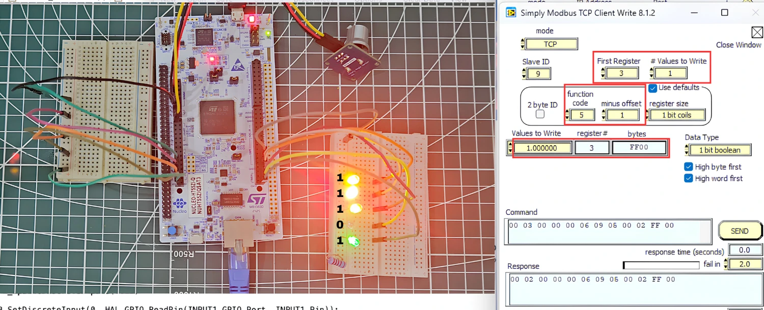
You can see the LED 3 is also turned ON. This indicates that the client is able to modify the states of the coils using the function code 5.
Writing single coil is woking fine, now we will try writing multiple coils at once.
Writing multiple coils (FC15)
Now we will use function code 15 to update the states of multiple coils at once. First I am resetting all 5 coils, starting from Coil 1, to 0. After sending the request, all 5 LEDs turn off, confirming that every coil was reset in one request.
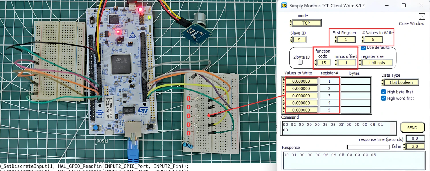
Next, we will set only coil 2 and coil 4, keeping the rest reset.
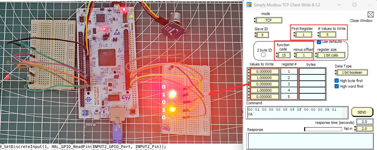
You can see only the second and fourth LEDs turn on, while the rest are still off. This confirms that both writing a single coil and writing multiple coils work as expected.
Conclusion
This completes the first half of our Modbus TCP series using the LWIP Ethernet library, which covered configuring STM32 as a Modbus server. The server can now handle function codes 1, 2, 3, 4, 5, 6, 15, and 16, which means it can read and write holding registers, read input registers, read and write coils, and read discrete inputs.
From the next part onwards, we will start working on configuring STM32 as a Modbus client, where the STM32 itself will send requests to a server, for reading and writing coils and registers.
If you have followed all the parts of this series, you should now be able to configure STM32 as a Modbus server. Let me know in the comments if you have any doubts.
Download Project Here
Download the CubeMX project files and HAL source code — all tested on real hardware.
If you find this useful, you can support us with a Donation as well.
Browse More STM32 TCP Tutorials
STM32 Modbus TCP Server using LWIP Part 3: Writing Holding Registers (FC06 & FC16)
STM32 Modbus TCP Server Part 4: Reading Coils and Discrete Inputs (FC01 & FC02)

STM32 Modbus TCP Client using LWIP Part 6: Setting Up the Client
STM32 Modbus TCP Client using LWIP – Part 7: Reading Registers and Coils
STM32 Modbus TCP Client using LWIP Part 8: Writing Registers and Coils

Subscribe
Login
0 Comments
Newest

