
Home ▸ STM32 Tutorials ▸ Modbus ▸ TCP ▸
Updated On: October 18, 2026
STM32 Modbus TCP Server: Writing Holding Registers (FC06 & FC16)
In part 2 of this series, we added function code 3 and function code 4 to our Modbus server, so the client was able to read both holding registers and input registers. That covered the read side of things.
In this part, we will handle function code 6 and function code 16, which let the client write into the holding registers. Function code 6 writes a single register, and function code 16 writes several registers in one request. We still cannot write to the input registers, since that data comes straight from the hardware, as we already covered in part 2. Writing only makes sense for the holding registers.
This is a continuation of the same project, so I am not repeating the Ethernet, LWIP, or ADC configuration here. If you haven’t gone through part 1 and part 2 yet, go do that first. There is also no CubeMX change for this part — the configuration stays exactly as it was. Only Modbus_Parser.c gets updated, so that is the only file we need to replace in the project.
This is the Part 3 in the STM32 Modbus TCP Series.
Table of contents
How Writing Registers Works
Function code 6 writes a single holding register. The client sends the address it wants to update along with the value, and the server writes that value into its database at that address.
Function code 16 writes multiple holding registers in a single request. Instead of one address and one value, the client sends a starting address, how many registers it wants to update, and the actual data for all of them, back to back. The server writes all of it in one go and tells the client how many registers were updated.
Both function codes only work on the holding register database from part 2, the one with 10 registers we defined in Modbus_Database.c. The input register array stays read-only, since it mirrors the ADC and there is nothing for a client to “write” there.
Function Code 6 Request and Response
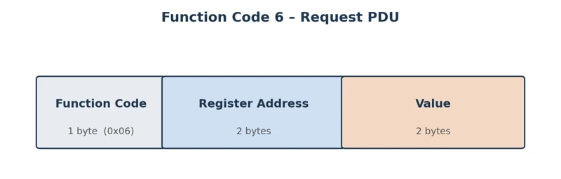
The PDU for a function code 6 request is small: one byte for the function code, two bytes for the register address, and two bytes for the value to write. I am only covering the PDU part here because the MBAP header remains the same in each case. It will always consist of Transaction ID, Protocol ID, Length and the Unit ID fields.
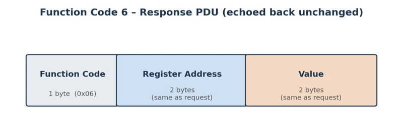
The response is the interesting part — the server just sends the exact same PDU back. Address and value, unchanged. That is how a Modbus client confirms a single-register write actually landed: if what comes back matches what it sent, the write succeeded.
Function Code 16 Request and Response
The request PDU for function code 16 is a bit longer: one byte for the function code, two bytes for the starting address, two bytes for the quantity of registers, one byte for the byte count, and then the actual data, two bytes per register.
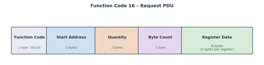
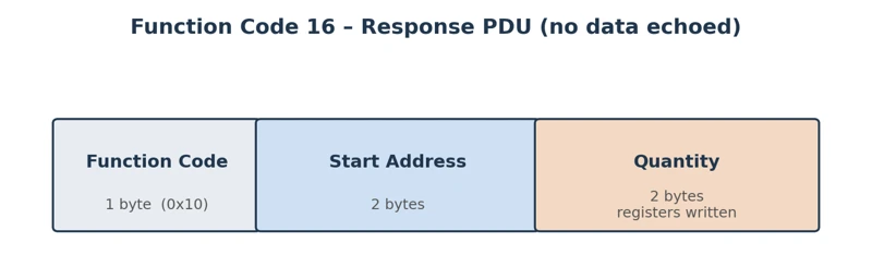
The response here does not echo the data back. It only confirms the function code, the starting address, and the quantity of registers that were written. Since the client already knows what it sent, there is no need to send the whole payload back a second time.
STM32 Modbus TCP Code updates
The Ethernet, LWIP, and ADC configuration is untouched from part 2. There is nothing new to generate from CubeMX for this tutorial, we are only modifying the Modbus_Parser.c file.
MB_ProcessFunction Changes
MB_ProcessFunction now has two more cases, for function code 6 and function code 16:
static err_t MB_ProcessFunction(struct tcp_pcb *pcb, MB_Request_t *req)
{
    switch(req->FunctionCode)
    {
    case MB_FC_READ_HOLDING_REGS:
        return MB_FC03_ReadHoldingRegisters(pcb, req);

    case MB_FC_READ_INPUT_REGS:
        return MB_FC04_ReadInputRegisters(pcb, req);

    case MB_FC_WRITE_SINGLE_REG:
        return MB_FC06_WriteSingleRegister(pcb, req);

    case MB_FC_WRITE_MULTI_REGS:
        return MB_FC16_WriteMultipleRegisters(pcb, req);

    default:
        return MB_SendException(pcb, req, MB_EX_ILLEGAL_FUNCTION);
    }
}It now can handle 4 function codes, for reading and writing the registers. Every other function code still falls through to default and gets an Illegal Function exception, exactly like before.
MB_FC06_WriteSingleRegister
This is a new function added to the Modbus_Parser.c file. It will be used to handle the function code 6.
The function first extracts the address and the value the client wants to write. Both are 16-bit values sitting right at the start of the request data:
address = ((uint16_t)req->Data[0] << 8) | req->Data[1];
value = ((uint16_t)req->Data[2] << 8) | req->Data[3];Before touching the database, we validate the address:
if(address >= MB_HOLDING_REG_COUNT)
return MB_SendException(pcb, req, MB_EX_ILLEGAL_DATA_ADDRESS);We only have 10 registers defined, so the client cannot ask to write to the 11th one. If it does, we send back an Illegal Data Address exception, the same exception we use when a read request goes out of bounds.
Once the address checks out, updating the database with a new value is very simple:
MB_HoldingRegs[address] = value;Now we build the response. The MBAP header copies the transaction ID from the request, keeps the protocol ID at 0, and the length is always 6 for this function code, since the response always carries the unit ID, function code, address, and value:
tx[0] = req->TransactionID >> 8;
tx[1] = req->TransactionID;
tx[2] = 0;
tx[3] = 0;
tx[4] = 0;
tx[5] = 6;
tx[6] = req->UnitID;
tx[7] = MB_FC_WRITE_SINGLE_REG;
tx[8] = address >> 8;
tx[9] = address;
tx[10] = value >> 8;
tx[11] = value;Notice that tx[8] through tx[11] are just the address and value copied straight from what the client sent. We are not reading anything back from the database here — the response is simply an acknowledgement that mirrors the request.
Once the buffer is ready, we call tcp_write and tcp_output, same as every other response in this server.
if(tcp_write(pcb, tx, sizeof(tx), TCP_WRITE_FLAG_COPY) != ERR_OK)
return ERR_MEM;
tcp_output(pcb);Below is the complete function.
static err_t MB_FC06_WriteSingleRegister(struct tcp_pcb *pcb, MB_Request_t *req)
{
uint16_t address;
uint16_t value;
uint8_t tx[12];
address = ((uint16_t)req->Data[0] << 8) | req->Data[1];
value   = ((uint16_t)req->Data[2] << 8) | req->Data[3];
printf("FC06 - Write Single Holding Register\r\n");
printf("Address : %u\r\n", address);
printf("Value : %u (0x%04X)\r\n", value, value);
/* Validate address */
if(address >= MB_HOLDING_REG_COUNT)
    return MB_SendException(pcb, req, MB_EX_ILLEGAL_DATA_ADDRESS);
/* Write Register */
MB_HoldingRegs[address] = value;
/* MBAP Header */
tx[0] = req->TransactionID >> 8;
tx[1] = req->TransactionID;
tx[2] = 0;
tx[3] = 0;
tx[4] = 0;
tx[5] = 6; // Unit ID + FC + Address + Value
tx[6] = req->UnitID;
tx[7] = MB_FC_WRITE_SINGLE_REG;
tx[8] = address >> 8;
tx[9] = address;
tx[10] = value >> 8;
tx[11] = value;
if(tcp_write(pcb, tx, sizeof(tx), TCP_WRITE_FLAG_COPY) != ERR_OK)
  return ERR_MEM;

tcp_output(pcb);
printf("FC06 Response Sent\r\n");
return ERR_OK;
}MB_FC16_WriteMultipleRegisters
This is another new function added to handle the function code 16. This one starts by extracting three values: the starting address, the quantity of registers, and the byte count. The first two are 16-bit, the byte count is just a single byte:
startAddr = ((uint16_t)req->Data[0] << 8) | req->Data[1];
quantity = ((uint16_t)req->Data[2] << 8) | req->Data[3];
byteCount = req->Data[4];Now we need to perform few checks. The first makes sure the quantity is not 0 and not more than 123:
if((quantity == 0) || (quantity > 123))
return MB_SendException(pcb, req, MB_EX_ILLEGAL_DATA_VALUE);This limit comes from the Modbus spec, same reasoning as the 125-register cap we saw for reading registers in part 2. We already know the PDU tops out at 253 bytes. Out of these 253 bytes, 1 Byte is used for the function code, 2 Bytes for the address, 2 Bytes for the quantity, and 1 Byte for the byte count fields. Now we are only left with 247 bytes for the actual data. Each register is 2 bytes, so 247 divided by 2 rounds down to 123 registers.
The second check makes sure the write does not run past our database, the same way we validate reads:
if((startAddr + quantity) > MB_HOLDING_REG_COUNT)
return MB_SendException(pcb, req, MB_EX_ILLEGAL_DATA_ADDRESS);Once both checks pass, we loop through the incoming data, combine each pair of bytes into a 16-bit value, and write it into the database:
for(i = 0; i < quantity; i++)
{
value = ((uint16_t)req->Data[5 + (i * 2)] << 8) | req->Data[6 + (i * 2)];
MB_HoldingRegs[startAddr + i] = value;
}The 5 + offset accounts for the address, quantity, and byte count fields that come before the data in the request — the actual register values start right after that.
The response for this function code is different from FC06. Instead of echoing the data, it only confirms the starting address and how many registers were written:
tx[0] = req->TransactionID >> 8;
tx[1] = req->TransactionID;
tx[2] = 0;
tx[3] = 0;
tx[4] = 0;
tx[5] = 6;
tx[6] = req->UnitID;
tx[7] = MB_FC_WRITE_MULTI_REGS;
tx[8] = startAddr >> 8;
tx[9] = startAddr;
tx[10] = quantity >> 8;
tx[11] = quantity;The length is again fixed at 6, since this response always has the same shape regardless of how many registers were actually written. Once the buffer is filled, we call tcp_write and tcp_output to send it out, same as always.
if(tcp_write(pcb, tx, sizeof(tx), TCP_WRITE_FLAG_COPY) != ERR_OK)
  return ERR_MEM;

tcp_output(pcb);
Below is the complete function.
static err_t MB_FC16_WriteMultipleRegisters(struct tcp_pcb *pcb, MB_Request_t *req)
{
uint16_t startAddr;
uint16_t quantity;
uint8_t byteCount;
uint16_t value;
uint16_t i;
uint8_t tx[12];
startAddr = ((uint16_t)req->Data[0] << 8) | req->Data[1];
quantity  = ((uint16_t)req->Data[2] << 8) | req->Data[3];
byteCount = req->Data[4];
printf("FC16 - Write Multiple Holding Registers\r\n");
printf("Start Address : %u\r\n", startAddr);
printf("Quantity : %u\r\n", quantity);
printf("Byte Count : %u\r\n", byteCount);
/* Validate quantity */
if((quantity == 0) || (quantity > 123))
    return MB_SendException(pcb, req, MB_EX_ILLEGAL_DATA_VALUE);
/* Validate address range */
if((startAddr + quantity) > MB_HOLDING_REG_COUNT)
    return MB_SendException(pcb, req, MB_EX_ILLEGAL_DATA_ADDRESS);
/* Write Registers */
for(i = 0; i < quantity; i++)
{
value = ((uint16_t)req->Data[5 + (i * 2)] << 8) | req->Data[6 + (i * 2)];
MB_HoldingRegs[startAddr + i] = value;
printf("Reg[%u] = %u (0x%04X)\r\n", startAddr + i, value, value);
}
/* MBAP Header */
tx[0] = req->TransactionID >> 8;
tx[1] = req->TransactionID;
tx[2] = 0;
tx[3] = 0;
tx[4] = 0;
tx[5] = 6; // Unit ID + FC + Address + Quantity
tx[6] = req->UnitID;
tx[7] = MB_FC_WRITE_MULTI_REGS;
tx[8] = startAddr >> 8;
tx[9] = startAddr;
tx[10] = quantity >> 8;
tx[11] = quantity;
if(tcp_write(pcb, tx, sizeof(tx), TCP_WRITE_FLAG_COPY) != ERR_OK)
  return ERR_MEM;

tcp_output(pcb);
printf("FC16 Response Sent\r\n");
return ERR_OK;
}That’s everything new in Modbus_Parser.c. No changes are needed in main.c for this part — the file from part 2 still works as it is.
Testing Server with Simply Modbus TCP Client
Flash the project and open the serial terminal on the ST-Link virtual COM port at 115200 baud, same as the last two parts. Open Simply Modbus TCP Client and connect to the server’s IP address on port 502.
Reading the holding registers first
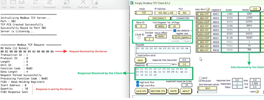
Set the function code to 3, the first register to 40001, and the number of registers to 10. This reads all 10 holding registers, so we have a baseline to compare against once we start writing.
Writing a single register (FC06)
Open a separate write window in Simply Modbus, set the function code to 6, and target register 40005. That register currently holds 0. Let’s write 12345 into it and send the request.
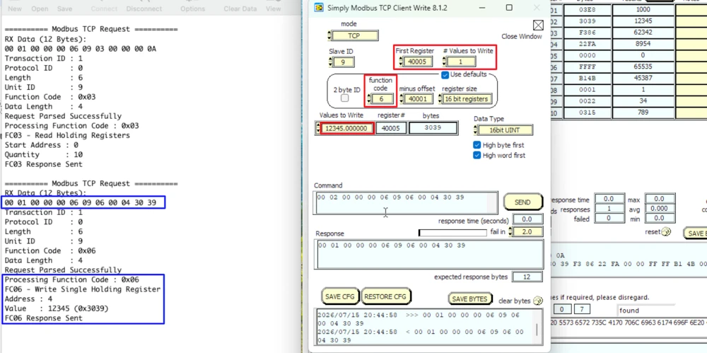
On the serial console, the server decodes the request and shows the starting address as 4 (since 40005 with an offset of 40001 maps to register 4) and the value as 12345. The response the client receives back is identical to what it sent, which is exactly the expected behavior for FC06.
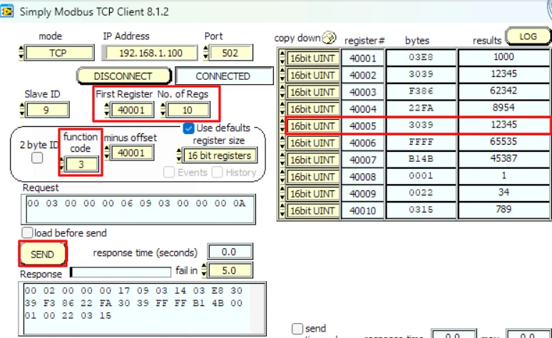
Read the holding registers again, and register 40005 now shows 12345.
Writing multiple registers (FC16)
Switch the function code to 16. This time, we write starting from register 40005 across six registers, 40005 through 40010, each with a different value. We have exactly 10 registers defined, so this stays inside the database.
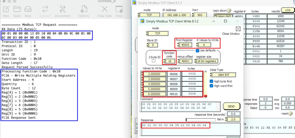
The server log shows the starting address as 4, the quantity as 6, and the byte count as 12, all matching what the client sent, along with each value it wrote. The response confirms the same starting address and quantity.
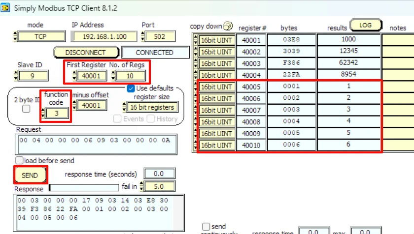
Reading the holding registers again shows 40005 through 40010 updated with the new values.
Writing outside the database
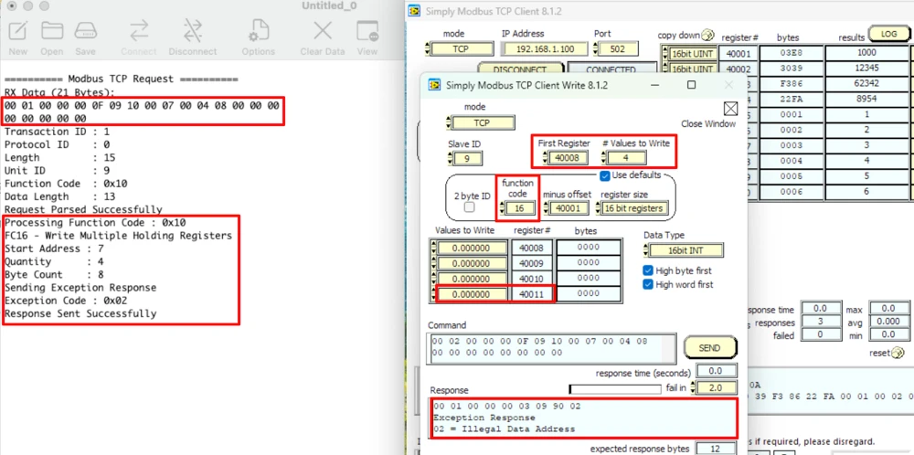
Now try writing 4 registers starting from 40008. That would touch register 40011, which does not exist in our 10-register database. Send this request, and the client receives an Illegal Data Address exception.
Conclusion
Our Modbus server is now able to handle function codes 3, 4, 6, and 16. The client can read and write the holding registers, read the input registers, and the server correctly rejects any request that falls outside the defined database, whether it’s a single-register write or a multi-register write. Between this part and the previous one, all the register-related operations are covered — a client can read data from the server, and it can also push new values into the holding registers whenever it needs to.
This also completes the register side of things for this series. From the next part onwards, we will start working with coils and discrete inputs, which follow a similar request-response structure but deal with single-bit values instead of 16-bit registers. We will first see how to read them using function code 1 and function code 2, and then how to write them using function code 5 and function code 15. Once registers, coils, and discrete inputs are all handled on the server side, we will move on to setting up the STM32 as a Modbus client instead of a server.
Download Project Here
Download the CubeMX project files and HAL source code — all tested on real hardware.
If you find this useful, you can support us with a Donation as well.
Browse More STM32 TCP Tutorials
STM32 LWIP Modbus TCP Tutorial: Server Setup (Part 1)
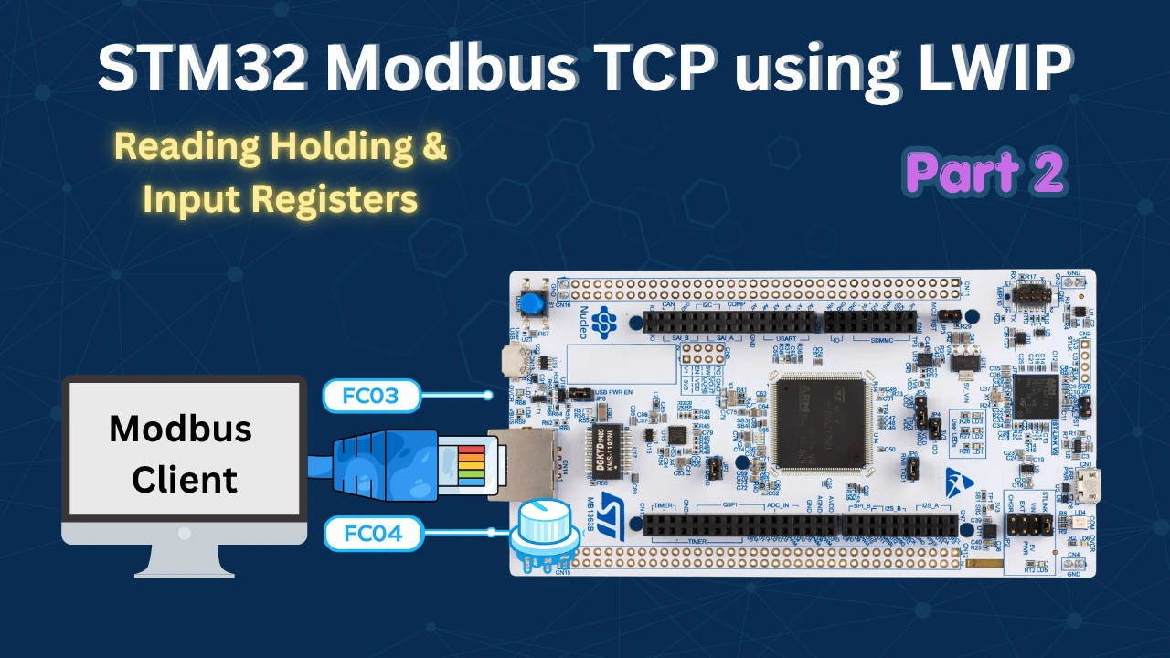
STM32 Modbus TCP (Part 2): Read Holding & Input Registers
STM32 Modbus TCP Server Part 4: Reading Coils and Discrete Inputs (FC01 & FC02)
STM32 Modbus TCP Server using LWIP Part 5: Writing Coils (FC05 & FC15)

STM32 Modbus TCP Client using LWIP Part 6: Setting Up the Client

Subscribe
Login
0 Comments
Newest

