
Home ▸ STM32 Tutorials ▸ Modbus ▸ TCP ▸
Updated On: October 18, 2026
STM32 Modbus TCP Server: Read Holding & Input Registers
In part 1 of this series, we configured the Ethernet peripheral and set up a basic Modbus TCP server on the STM32. That server was able to receive a request and reply to it, but the reply was always an exception, because we had not handled any function code yet.
In this part, we will start handling function codes. We will begin with function code 3 and function code 4, which are used to read holding registers and input registers. This is a continuation of the previous project, so I am not going to repeat the Ethernet or LWIP configuration here. If you have not gone through part 1 yet, I would recommend doing that first.
We will add a couple of new files to the project, update the parser, and add a bit of configuration in CubeMX for the ADC. To demonstrate the input registers, I am also going to connect a potentiometer to the board, so we can read a live, changing value through Modbus.
This is the Part 2 in the STM32 Modbus TCP Series.
Table of contents
How Holding and Input Registers Work
Function code 3 is used to read holding registers. These are 16-bit registers, and their addresses run from 40001 all the way up to 49999. The data for these registers lives on the server, so the client is really just asking the server to hand over whatever is already stored at a given address.
Function code 4 reads input registers. Their addresses ranges from 30001 to 39999. The reading works similar to how it happens in Holding Registers. The difference is in what the register actually represents. A holding register is stored data, the kind of thing you set once and it stays put until something changes it. An input register is not stored data as such, it reflects whatever is coming in from a hardware device connected to the server. That could be a sensor, an ADC reading, or anything else external that the server wants to expose to a Modbus client.
To demonstrate this properly, I am using a potentiometer connected to the board. The server reads the potentiometer through the ADC, stores that value inside the input register database, and keeps updating it continuously. The client can then read this updated value whenever it wants, and it will always get the latest reading.
Register Map on the STM32 Server
We keep the register data in two new files, Modbus_Database.h and Modbus_Database.c. The header defines how many registers we have in each database:
#define MB_HOLDING_REG_COUNT    10
#define MB_INPUT_REG_COUNT 10This tells the server how many registers exist in each database, and we use this count later on to check incoming requests. A client should never be able to ask for a register that does not exist on our server. I am defining 10 registers because it is easier to demonstrate with fewer registers. You can define upto 9999 registers if your MCU’s memory allows it.
The holding register array is filled with sample values right away, since holding registers are meant to hold data we define ourselves:
uint16_t MB_HoldingRegs[MB_HOLDING_REG_COUNT] = {
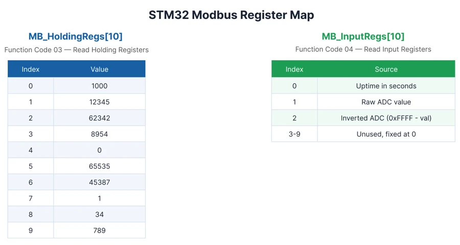
    1000, 12345, 62342, 8954, 0, 65535, 45387, 1, 34, 789,
};The input register array, on the other hand, starts out at all zeros:
uint16_t MB_InputRegs[MB_INPUT_REG_COUNT] = {0};This is because input registers are hardware-dependent. Whatever we put into this array comes from actual hardware, in our case the potentiometer through the ADC. We cannot connect a Modbus request directly to a piece of hardware, so this array acts as a buffer sitting in between. That buffer needs to be refreshed periodically, and that is exactly what MB_UpdateInputRegisters does:
void MB_UpdateInputRegisters(void)
{
    uint16_t adcVal = readADC();
    MB_InputRegs[0] = HAL_GetTick() / 1000;
    MB_InputRegs[1] = adcVal;
    MB_InputRegs[2] = 0xFFFF - adcVal;
}Register 0 stores the uptime in seconds, just so we have a value to watch that keeps changing on its own. Register 1 stores the raw ADC reading, and register 2 stores the same value inverted, subtracted from 0xFFFF. You could just as easily store temperature in one element, pressure in the next, humidity after that, and so on. This function will keep running and filling in whatever values you want.
To read the ADC, this file calls an external function called readADC, which we will define inside main.c a little later.
The image below shows the register map we are using in this tutorial, holding registers on the left and input registers on the right.
Wiring the Potentiometer
I am going to connect the potentiometer to pin PA3 on the Nucleo board, which is basically the ADC1 channel 15. The potentiometer is powered with 3.3V straight from the STM32 board itself, and the wiper pin goes to PA3.
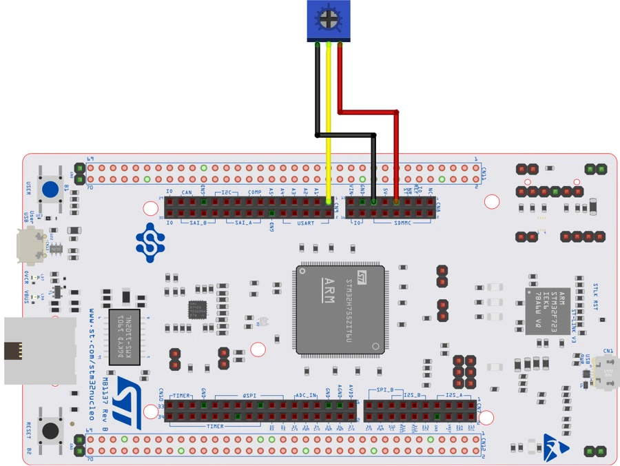
- One outer pin of the potentiometer to 3.3V
- The other outer pin to GND
- The wiper (middle pin) to PA3
Keep the wiper wire short and away from the Ethernet lines, since a noisy ADC reading will make the input register value jump around more than it should.
STM32 Modbus TCP Code
The Ethernet, LWIP, and MPU configuration stays exactly as it was in part 1, we are not touching any of that again. The only new piece on the CubeMX side is the ADC.
ADC1 Configuration
Since PA3 is ADC1 channel 15, we need to enable this channel for the Cortex-M7 core. The image below shows the ADC1 configuration used for this tutorial, with channel 15 enabled.
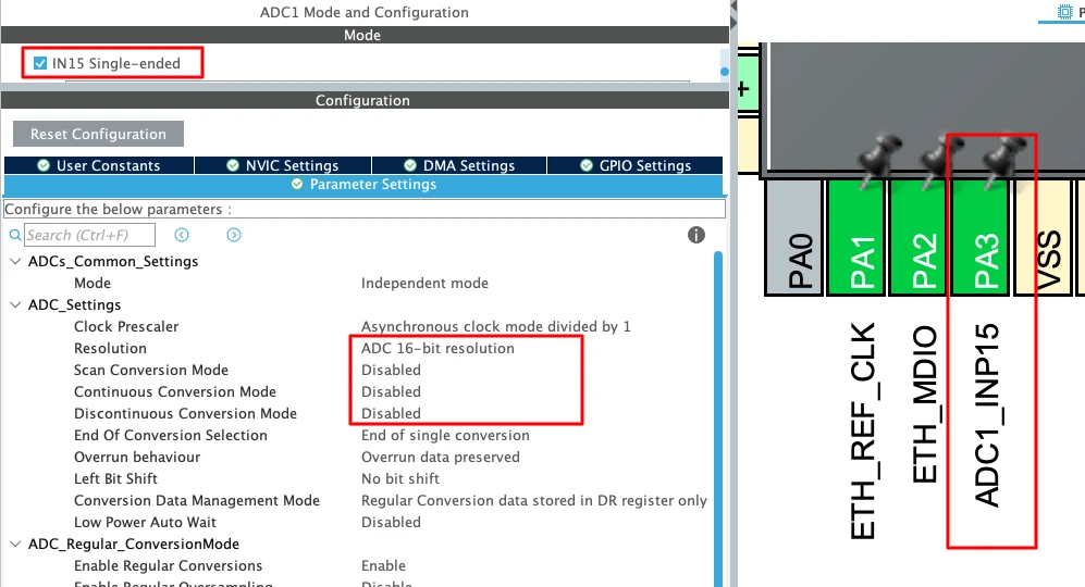
The resolution is set to 16-bit by default, and we will leave it as it is, since our registers are also 16 bits wide and this fits perfectly. I am leaving the rest of the parameters at their default settings, and we will read the ADC in blocking mode, since I do not want to bring interrupts into this tutorial.
Once the channel is enabled, open the clock configuration tab. You will likely see an error here, because the ADC ends up clocked at a very high frequency by default. Change the ADC clock source to the peripheral clock, which brings it down to 64 MHz and clears the error.
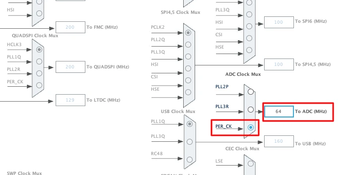
That is all the configuration the ADC needs. Click Generate Code, and CubeMX will add the ADC initialization to the project alongside everything we already had from part 1.
Modbus_Parser.c Changes
The parser file from part 1 gets two new functions, one for each function code, plus an update to MB_ProcessFunction so it actually calls them.
MB_ProcessFunction now has real cases for function code 3 and function code 4, instead of falling straight through to the exception:
static err_t MB_ProcessFunction(struct tcp_pcb *pcb, MB_Request_t *req)
{
    switch(req->FunctionCode)
    {
    case MB_FC_READ_HOLDING_REGS:
        return MB_FC03_ReadHoldingRegisters(pcb, req);

    case MB_FC_READ_INPUT_REGS:
        return MB_FC04_ReadInputRegisters(pcb, req);

    default:
        return MB_SendException(pcb, req, MB_EX_ILLEGAL_FUNCTION);
    }
}Every other function code still falls into default and gets an exception, exactly as before.
MB_FC03_ReadHoldingRegisters receives the parsed request, and the first thing it does is pull out the starting address and the quantity of registers the client is asking for. Both of these are 16-bit values sitting right at the start of the request data:
startAddr = ((uint16_t)req->Data[0] << 8) | req->Data[1];
quantity = ((uint16_t)req->Data[2] << 8) | req->Data[3];Once we have these two values, we run two checks before touching the register array. The first check makes sure the quantity is not 0, and not more than 125:
if((quantity == 0) || (quantity > 125))
return MB_SendException(pcb, req, MB_EX_ILLEGAL_DATA_VALUE);The 125 limit comes straight from the Modbus specification, not from us. A Modbus PDU is capped at 253 bytes. For a register read response, 1 byte goes to the function code and 1 byte goes to the byte count, which leaves 251 bytes for the actual register data. Each register takes up 2 bytes, so 251 divided by 2 works out to 125 registers, and not one more. If the client asks for more than this, we send back an Illegal Data Value exception.
The second check makes sure the client is only asking for registers that actually exist in our database:
if((startAddr + quantity) > MB_HOLDING_REG_COUNT)
return MB_SendException(pcb, req, MB_EX_ILLEGAL_DATA_ADDRESS);We only defined 10 registers, so a client cannot ask for, say, the eleventh one. If it tries, we send an Illegal Data Address exception instead.
Once both checks pass, we start building the response. We copy the transaction ID from the request, keep the protocol ID at 0, and calculate the length field based on how many registers were requested:
tx[0] = req->TransactionID >> 8;
tx[1] = req->TransactionID;
tx[2] = 0;
tx[3] = 0;
tx[4] = 0;
tx[5] = 3 + (quantity * 2);
tx[6] = req->UnitID;
tx[7] = MB_FC_READ_HOLDING_REGS;
tx[8] = quantity * 2;The length in tx[5] covers the unit ID, function code, byte count, and all the register data that follows, so it grows along with the requested quantity. tx[8] is the byte count itself, which is just the number of registers multiplied by 2, since each register takes up 2 bytes.
After the header, we loop through the holding register array starting from startAddr, and copy each value into the transmit buffer, high byte first:
for(i = 0; i < quantity; i++)
{
    uint16_t value = MB_HoldingRegs[startAddr + i];
    tx[txLen++] = value >> 8;
    tx[txLen++] = value;
}Once everything is copied, we call tcp_write to queue the response and tcp_output to actually send it out to the client.
MB_FC04_ReadInputRegisters works in exactly the same way. The only real difference is that it reads from MB_InputRegs instead of MB_HoldingRegs, checks against MB_INPUT_REG_COUNT, and writes MB_FC_READ_INPUT_REGS into the function code byte of the response.
The image below shows how a request for function code 3 or function code 4 moves from the parser into the matching handler and back out as a response.
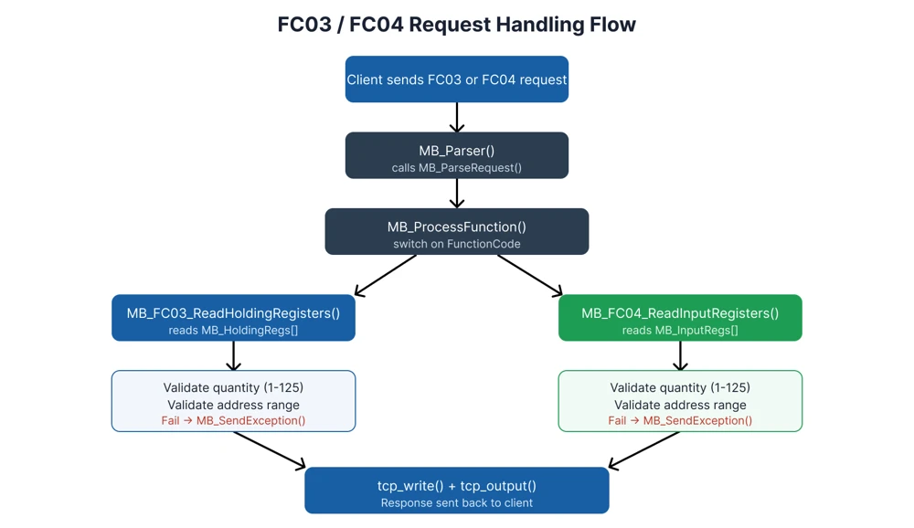
That covers everything new in Modbus_Parser.c.
main.c Changes
Inside the main.c, we need to write the readADC function that the database file is calling externally. It starts the ADC, polls until the conversion completes, reads the value, stops the ADC, and returns the result:
uint16_t readADC(void)
{
    HAL_ADC_Start(&hadc1);
    HAL_ADC_PollForConversion(&hadc1, 100);
    uint16_t val = HAL_ADC_GetValue(&hadc1);
    HAL_ADC_Stop(&hadc1);
    return val;
}We also need to call MB_UpdateInputRegisters periodically, so the input register database stays fresh. There are several ways to do this, you could use a separate task if you are running an RTOS, a timer callback, or even the ADC interrupt. I prefer keeping it simple with the STM32’s tick counter. We define a variable to track the last update time, and inside the infinite loop we check if 500 milliseconds have passed:
uint32_t prevTick = 0;
extern void MB_UpdateInputRegisters(void);

while (1)
{
    MX_LWIP_Process();

    if ((HAL_GetTick() - prevTick) > 500)
    {
        prevTick = HAL_GetTick();
        MB_UpdateInputRegisters();
    }
}This way, the update only runs once every 500 milliseconds, and the rest of the time MX_LWIP_Process keeps running without being held up. If you build the project at this stage and get an error about MB_UpdateInputRegisters not being declared, that is because it is defined in the database file but not declared anywhere main.c can see it, which is exactly why we declared it as external above.
Modbus TCP Test and Result
Flash the project and open the serial terminal on the ST-Link virtual COM port at 115200 baud, same as before. The log should confirm the server is bound and listening on port 502.
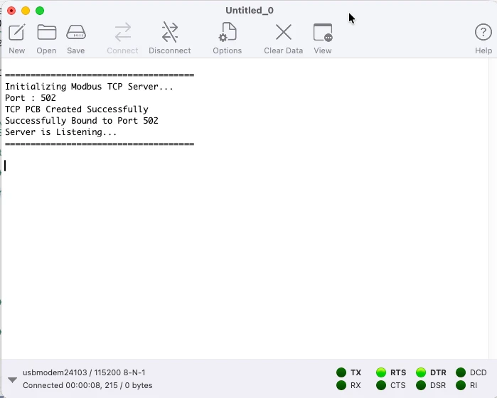
Open Simply Modbus TCP Client and connect to the server’s IP address on port 502.
Reading holding registers
Set the function code to 3, the first register to 40001, and the number of registers to 10. Since the offset for holding registers is 40001, the server sees this as a request starting from register 0.
The image below shows the response received for this request.
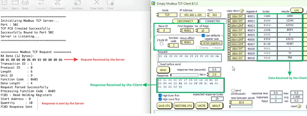
The data matches exactly what we stored in MB_HoldingRegs.
Now let’s request from a different starting point. Set the first register to 40005 and the number of registers to 5. With the same offset, the server sees this as a request starting from register 4, for 5 registers.
The image below shows the output for this request.
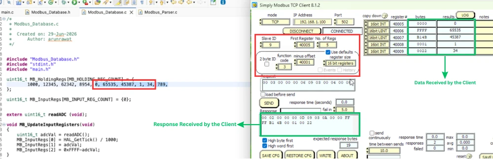
We defined only 10 registers, from 40001 to 40010. So if we request 7 registers starting from 40005, the client is effectively asking for register 40011 too, which does not exist. Let’s send this request and see what happens.
The image below shows the exception received when requesting registers beyond what the server has defined.
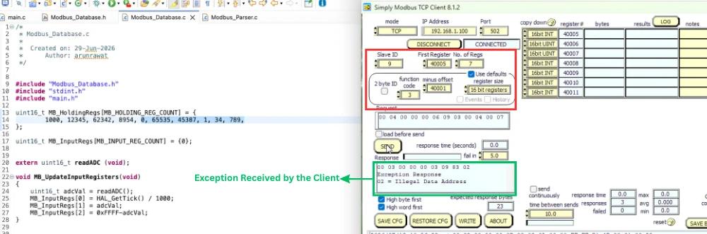
The server responds with an Illegal Data Address exception, exactly as we programmed it to.
Reading input registers
Switch the function code to 4, and set the first register to 30001, which is the standard offset for input registers. With this offset, the server sees the request starting from register 0.
The image below shows the response for the first three input registers, with the rest at zero.
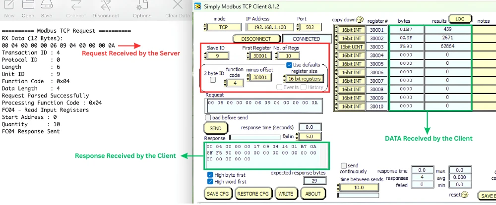
You can see the uptime in seconds in the first register, the raw ADC value in the second, and the inverted ADC value in the third.
Now rotate the potentiometer to one extreme and send the request again. The ADC value should move close to its maximum, and the inverted value should drop close to zero.
The image below shows the input registers updating after turning the potentiometer.
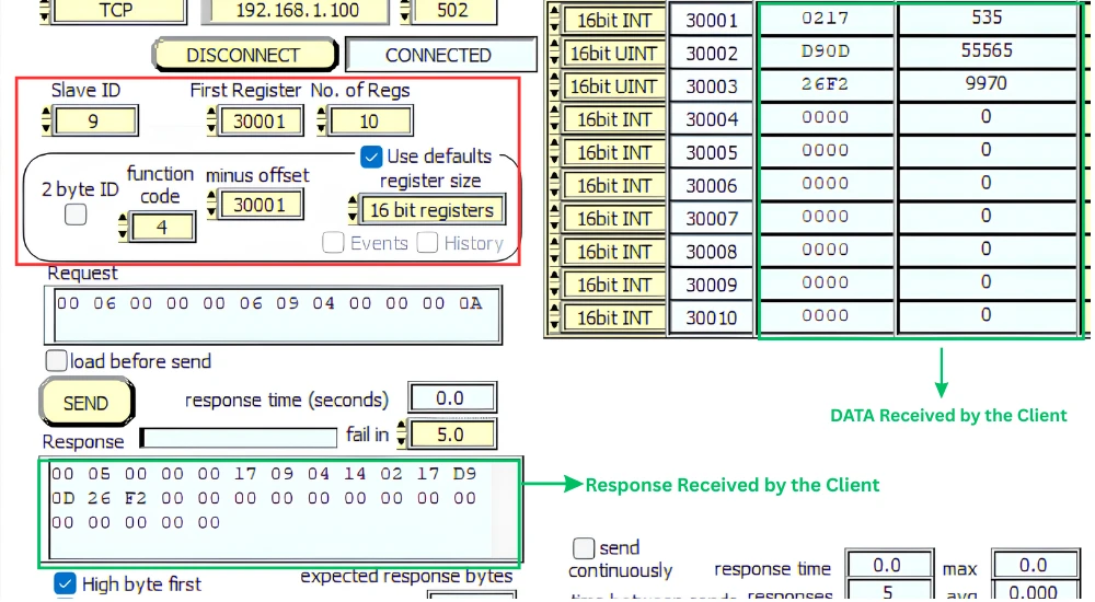
Turn the potentiometer to somewhere in the middle and send the request one more time. The two values should sit closer together now, and the uptime register should keep climbing regardless of where the potentiometer sits. The ADC is not calibrated here, so you may not see the exact minimum or maximum values, but that is not the point of this tutorial. What matters is that we are reading live hardware data and exposing it through Modbus.
Function code 3 and function code 4 are now both working correctly, and the server correctly rejects any request that goes outside the defined register range. In the next part, we will add write support with function code 6 and function code 16.
Conclusion
Function code 3 and function code 4 are now both working on our server. We can read a fixed set of holding registers and a live, hardware-driven set of input registers, and the server correctly rejects any request that asks for more registers than we have, or more than the Modbus specification allows. That covers the read side of Modbus TCP.
In the next part of this series, we will move to the write side, function code 6 for writing a single register and function code 16 for writing multiple registers at once. That will let a client actually change values on the server, instead of just reading them.
Download Project Here
Download the CubeMX project files and HAL source code — all tested on real hardware.
If you find this useful, you can support us with a Donation as well.
Browse More STM32 TCP Tutorials

STM32 LWIP Modbus TCP Tutorial: Server Setup (Part 1)
STM32 Modbus TCP Server using LWIP Part 3: Writing Holding Registers (FC06 & FC16)
STM32 Modbus TCP Server Part 4: Reading Coils and Discrete Inputs (FC01 & FC02)
STM32 Modbus TCP Server using LWIP Part 5: Writing Coils (FC05 & FC15)

STM32 Modbus TCP Client using LWIP Part 6: Setting Up the Client

Subscribe
Login
0 Comments
Newest

