
Home ▸ STM32 Tutorials ▸ Modbus ▸ TCP ▸
Updated On: October 18, 2026
STM32 Modbus TCP Client using LWIP: Writing Registers and Coils
This is Part 8 in the STM32 Modbus TCP series using the LwIP Ethernet library. In Part 6, we configured the STM32 as a Modbus TCP client. In Part 7, we extended the STM32 Modbus client to read holding registers, input registers, coils, and discrete inputs from the server. We also saw how the client handles an exception response when the requested data is not available.
Today, we will continue building our Modbus Client. On top of reading data from the server, our STM32 client will now modify it. This means we will handle function codes 5, 6, 15, and 16. Function codes 5 and 15 are used to write a single coil and multiple coils, while function codes 6 and 16 are used to write a single register and multiple registers.
Once the client sends a write request, the server updates its own database and sends a confirmation back. The client decodes this confirmation and prints the result on the serial console. After the write requests, we will also read the same registers and coils back, just to confirm that the data was actually modified on the server.
This is Part 8 of the STM32 Modbus TCP Series.
Table of contents
How the STM32 Modbus Client Writes Registers and Coils
I am continuing from the same project we left off in Part 7. Since we are only adding the ability to write data, three files need to change: the two Modbus_Client_Request.c, Modbus_Client_Request.h and the Modbus_Client_Parser.c file. If you are copying these files into your own project, remember to overwrite the ones already present, since they were created in the earlier parts of this series.
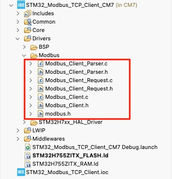
Here are the changes made in each of these files, along with main.c:
- Modbus_Client_Request.c : added four new functions. One for each write function code, which build the request frame and send it to the server.
- Modbus_Client_Parser.c : added four new handler functions that decode the confirmation the server sends back after a write, and print the result on the serial console.
- main.c : now cycles through six cases instead of four with every button press, four for writing and two for reading the data back.
Modbus Client Request Functions for Writing Data
Let’s start with understanding the file Modbus_Client_Request.c. Four new functions have been added here: MB_WriteSingleRegister, MB_WriteMultipleRegisters, MB_WriteSingleCoil, and MB_WriteMultipleCoils. The overall structure of the MBAP header stays the same as what we built for the read functions in Part 7, so we will mainly focus on what is different for each of these.
MB_WriteSingleRegister
This function takes four parameters:
- transaction ID
- unit ID of the server
- 16-bit address where we want to write the data
- 16-bit value we want to write
err_t MB_WriteSingleRegister(uint16_t txnID, uint8_t unitID, uint16_t addr, uint16_t value)
{
    MB_CurrentRequest.StartAddress = addr;

    uint8_t tx[12];

    /* MBAP Header */

    // Transaction ID
    tx[0] = txnID >> 8;
    tx[1] = txnID;

    // Protocol ID
    tx[2] = 0;
    tx[3] = 0;

    // Length
    tx[4] = 0;
    tx[5] = 6;

    // Unit ID
    tx[6] = unitID;

    /* PDU */

    // Function Code
    tx[7] = MB_FC_WRITE_SINGLE_REG;

    // Register Address
    tx[8] = addr >> 8;
    tx[9] = addr;

    // Register Value
    tx[10] = value >> 8;
    tx[11] = value;

    /* Send the Request */
    return TCP_SendRequest(tx, 12);
}The MBAP header here is prepared exactly the way we saw in Part 7, with a fixed length of 6 bytes.
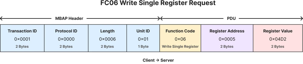
The PDU is made up of one byte for the functioncode, two bytes for the address, and two bytes for the value we want to write. This gives us a total of 12 bytes for the entire request.
After building the request, we call the function TCP_SendRequest to send the request to the server.
MB_WriteMultipleRegisters
This function is a little different, since we are no longer sending a single value. We are sending an entire array of 16-bit values to the server, along with the quantity of registers we want to write.
This function takes five parameters:
- transaction ID
- unit ID of the server
- 16-bit address where we want to start writing the data from
- 16-bit quantity indicating how many registers we want to write
- pointer to the 16-bit data array, that we want to write
err_t MB_WriteMultipleRegisters(uint16_t txnID, uint8_t unitID, uint16_t addr, uint16_t qty, uint16_t *data)
{
    MB_CurrentRequest.StartAddress = addr;
    MB_CurrentRequest.Quantity = qty;

    uint8_t tx[260];
    uint8_t byteCount = qty * 2;

    /* MBAP Header */

    // Transaction ID
    tx[0] = txnID >> 8;
    tx[1] = txnID;

    // Protocol ID
    tx[2] = 0;
    tx[3] = 0;

    // Length
    tx[4] = (7 + byteCount) >> 8;
    tx[5] = (7 + byteCount);

    // Unit ID
    tx[6] = unitID;

    /* PDU */

    // Function Code
    tx[7] = MB_FC_WRITE_MULTI_REGS;

    // Starting Address
    tx[8] = addr >> 8;
    tx[9] = addr;

    // Quantity
    tx[10] = qty >> 8;
    tx[11] = qty;

    // Byte Count
    tx[12] = byteCount;

    /* Register Data */

    for(uint16_t i = 0; i < qty; i++)
    {
        tx[13 + (i * 2)] = data[i] >> 8;
        tx[14 + (i * 2)] = data[i];
    }

    /* Send the Request */
    return TCP_SendRequest(tx, 13 + byteCount);
}At the beginning, we calculate the bytecount, which depends on how many registers we are writing. Since each register in the Modbus database is 16 bits wide, the bytecount is simply twice the quantity.
The length field in the MBAP header is no longer fixed, because it now depends on how much data we are sending. We calculate it by adding the byte count to 7, since there are seven fixed bytes that follow the length field: the unit ID, the function code, the start address, the quantity, and the byte count itself. On top of these seven bytes, we add the actual register data, which is why the byte count gets added to 7.

The PDU consists of the function code, the start address, the quantity of registers we want to write, and the bytecount, which tells the server how many data bytes will follow. After this, we copy the actual register values into the transmit buffer, two bytes at a time.Finally we send the complete request using TCP_SendRequest.
MB_WriteSingleCoil
Writing a single coil is similar to writing a single register. We only need to pass the address of the coil we want to modify and the value we want to set. The value can be either 1 to turn the coil on, or 0 to turn it off.
This function takes four parameters:
- transaction ID
- unit ID of the server
- 16-bit address where we want to write the data
- 8-bit value we want to write (either 1 or 0)
err_t MB_WriteSingleCoil(uint16_t txnID, uint8_t unitID, uint16_t addr, uint8_t value)
{
    MB_CurrentRequest.StartAddress = addr;

    uint8_t tx[12];

    /* MBAP Header */

    // Transaction ID
    tx[0] = txnID >> 8;
    tx[1] = txnID;

    // Protocol ID
    tx[2] = 0;
    tx[3] = 0;

    // Length
    tx[4] = 0;
    tx[5] = 6;

    // Unit ID
    tx[6] = unitID;

    /* PDU */

    // Function Code
    tx[7] = MB_FC_WRITE_SINGLE_COIL;

    // Output Address
    tx[8] = addr >> 8;
    tx[9] = addr;

    // Output Value
    if(value)
    {
        tx[10] = 0xFF;
        tx[11] = 0x00;
    }
    else
    {
        tx[10] = 0x00;
        tx[11] = 0x00;
    }

    /* Send the Request */
    return TCP_SendRequest(tx, 12);
}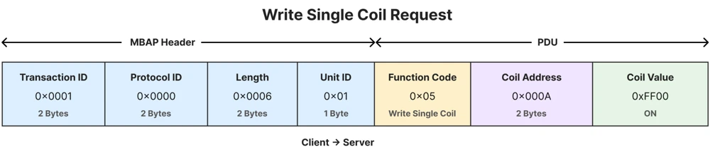
The MBAP header is prepared in the same way as MB_WriteSingleRegister, with the length fixed at 6 bytes. The value field is a little different here. According to the Modbus specification, a client turns a coil on by sending the value 0xFF00, and turns it off by sending 0x0000. So depending on the value passed to the parameter of the function, we copy the correct pair of bytes into the transmit buffer before sending the request.
MB_WriteMultipleCoils
The last function writes multiple coils in one request. Its parameters include the quantity of coils we want to write, along with a data array where each element represents the value of one coil.
err_t MB_WriteMultipleCoils(uint16_t txnID, uint8_t unitID, uint16_t addr, uint16_t qty, uint8_t *data)
{
    MB_CurrentRequest.StartAddress = addr;
    MB_CurrentRequest.Quantity = qty;

    uint8_t tx[260];
    uint8_t byteCount = (qty + 7) / 8;

    /* MBAP Header */

    // Transaction ID
    tx[0] = txnID >> 8;
    tx[1] = txnID;

    // Protocol ID
    tx[2] = 0;
    tx[3] = 0;

    // Length
    tx[4] = 0;
    tx[5] = 7 + byteCount;

    // Unit ID
    tx[6] = unitID;

    /* PDU */

    // Function Code
    tx[7] = MB_FC_WRITE_MULTI_COILS;

    // Starting Address
    tx[8] = addr >> 8;
    tx[9] = addr;

    // Quantity
    tx[10] = qty >> 8;
    tx[11] = qty;

    // Byte Count
    tx[12] = byteCount;

    /* Coil Data */

    for(uint8_t i = 0; i < byteCount; i++)
    {
        tx[13 + i] = 0;

        for(uint8_t bit = 0; bit < 8; bit++)
        {
            uint16_t index = (i * 8) + bit;

            if(index >= qty)
                break;

            if(data[index])
            {
                tx[13 + i] |= (1 << bit);
            }
        }
    }

    /* Send the Request */
    return TCP_SendRequest(tx, 13 + byteCount);
}Since each coil takes up only a single bit, and data is always sent in complete bytes. We group the coils into sets of eight, with each byte holding up to eight of them. If the number of coils is not an exact multiple of eight, we still need one extra byte for the remaining coils, even if that byte is not completely filled. This is why the byteCount is calculated as (qty + 7) / 8.
The MBAP header is built the same way as the other write functions, except that the length now depends on the byteCount instead of staying fixed. The PDU begins with the function code, the start address, the quantity of coils, and the byte count, followed by the actual coil data.

To copy this data bit by bit, we use two nested loops. The outer loop runs once for each byte in the byte count, and for every byte, the inner loop runs eight times, once for each bit inside it. For every bit, we look at the matching element in the data array and set that bit high or low at the correct position in the transmit buffer. Since every byte starts out at zero, any bit we do not explicitly set simply stays at zero. This takes care of any unused bits in the last byte.
Parsing the Write Confirmation from the Server
Once the server processes a write request, it sends a short confirmation back to the client. This response is received by tcp_client_recv, exactly as we saw in Part 7. The response is passed along to MB_Client_Parser. I have added Four new cases to this switch statement, one for each write function code.
switch(FunctionCode)
{
    case MB_FC_READ_HOLDING_REGS:
        return MB_ParseReadHoldingRegisters(rx);

    case MB_FC_READ_INPUT_REGS:
        return MB_ParseReadInputRegisters(rx);

    case MB_FC_READ_COILS:
        return MB_ParseReadCoils(rx);

    case MB_FC_READ_DISCRETE_INPUTS:
        return MB_ParseReadDiscreteInputs(rx);

    case MB_FC_WRITE_SINGLE_COIL:
        return MB_ParseWriteSingleCoil(rx);

    case MB_FC_WRITE_MULTI_COILS:
        return MB_ParseWriteMultipleCoils(rx);

    case MB_FC_WRITE_SINGLE_REG:
        return MB_ParseWriteSingleRegister(rx);

    case MB_FC_WRITE_MULTI_REGS:
        return MB_ParseWriteMultipleRegisters(rx);

    default:
        printf("Unsupported Function Code : %d\r\n", FunctionCode);
        break;
}A write confirmation is much shorter than a read response. The server does not need to send any data back, it only needs to echo the address and value, or the address and quantity, to confirm what was written.
MB_ParseWriteSingleRegister
static err_t MB_ParseWriteSingleRegister(uint8_t *rx)
{
    uint16_t address = ((uint16_t)rx[8] << 8) | rx[9];
    uint16_t value   = ((uint16_t)rx[10] << 8) | rx[11];

    printf("Address : %u\r\n", address);
    printf("Value   : %u\r\n", value);

    return ERR_OK;
}Here, we simply pull the address from index 8 and 9, and the value from index 10 and 11 of the response, and print them on the serial console. This confirms that the register at this address has been updated with this value on the server.
The other write-confirmation parsers, MB_ParseWriteSingleCoil, MB_ParseWriteMultipleRegisters, and MB_ParseWriteMultipleCoils, work in a similar way. Each one reads the relevant fields from the response and prints them on the serial console.
static err_t MB_ParseWriteMultipleRegisters(uint8_t *rx)
{
    uint16_t startAddress = ((uint16_t)rx[8] << 8) | rx[9];
    uint16_t quantity     = ((uint16_t)rx[10] << 8) | rx[11];

    printf("\r\nWrite Multiple Registers Response\r\n");
    printf("---------------------------------\r\n");

    printf("Start Address : %u\r\n", startAddress);
    printf("Quantity      : %u\r\n", quantity);

    printf("\r\n");

    return ERR_OK;
}

static err_t MB_ParseWriteSingleCoil(uint8_t *rx)
{
    uint16_t address = ((uint16_t)rx[8] << 8) | rx[9];
    uint16_t value   = ((uint16_t)rx[10] << 8) | rx[11];

    printf("\r\nWrite Single Coil Response\r\n");
    printf("---------------------------\r\n");

    printf("Address : %u\r\n", address);

    if(value == 0xFF00)
    {
        printf("Value   : ON\r\n");
    }
    else if(value == 0x0000)
    {
        printf("Value   : OFF\r\n");
    }
    else
    {
        printf("Value   : 0x%04X\r\n", value);
    }

    printf("\r\n");

    return ERR_OK;
}


static err_t MB_ParseWriteMultipleCoils(uint8_t *rx)
{
    uint16_t startAddress = ((uint16_t)rx[8] << 8) | rx[9];
    uint16_t quantity     = ((uint16_t)rx[10] << 8) | rx[11];

    printf("\r\nWrite Multiple Coils Response\r\n");
    printf("-----------------------------\r\n");

    printf("Start Address : %u\r\n", startAddress);
    printf("Quantity      : %u\r\n", quantity);

    printf("\r\n");

    return ERR_OK;
}Triggering Write Requests from main.c
Inside main.c, we keep the button handling exactly as it was in Part 7.
int counter = 0;
volatile int isPressed = 0;

void HAL_GPIO_EXTI_Callback(uint16_t GPIO_Pin)
{
	isPressed = 1;
}The only change is inside the switch statement, where we now handle six cases instead of four.
  while (1)
  {
	  MX_LWIP_Process();
	  Modbus_Client_Process("192.168.1.10", 502);

	  if (isPressed == 1)
	  {
		  HAL_Delay(200);  // debouncing
		  isPressed = 0;
		  counter++;

		  switch (counter)
		  {
		 	case 1:
		 		MB_WriteSingleRegister(counter, 1, 5, 8888);
		 		break;
		 	case 2:
		 		uint16_t  regs[3] = {1111, 2222, 3333};
		 		MB_WriteMultipleRegisters(counter, 1, 7, 3, regs);
		 		break;
		 	case 3:
		 		MB_WriteSingleCoil(counter, 1, 5, 0);
		 		break;
		 	case 4:
		 		uint8_t coils[6] = {0, 0, 0, 0, 0, 0};
		 		MB_WriteMultipleCoils(counter, 1, 10, 6, coils);
		 		break;
		 	case 5:
		 		MB_ReadHoldingRegisters(counter, 1, 0, 10);
		 		break;
		 	case 6:
		 		MB_ReadCoils(counter, 1, 0, 16);
		 		break;

		  default:
			  break;
		  }

		  if (counter >= 6) counter = 0;
	  }
}- The first press writes the value 8888 into register number 5.
- The second press writes three registers, 7, 8, and 9, using the values stored in the
regsarray. - The third press turns coil number 5 off by writing a value of 0 to it.
- The fourth press writes data for six coils, starting from coil number 10, using the values stored in the
coilsarray.
The last two cases are not write requests at all. They read the holding registers and the coils back from the server, so that we can confirm the data we just wrote is actually present on the server’s database. Since the counter now goes up to 6, we also update the reset condition, so the sequence starts again from writing a single register once the sixth button press is done.
Modbus Client Testing – Writing Registers and Coils
For testing, I am using the Python based Modbus server, with a database of 16 coils and 10 holding registers. Every time the client sends a write request, the server updates the value in its database and sends a confirmation back.
COILS = [
    1,0,1,1,0,1,0,0,
    1,1,0,0,1,0,1,0
]

INPUTS = [
    0,1,0,0,1,1,0,1,
    1,0,1,0,0,1,0,1
]

HOLDING_REGS = [
    100,101,102,103,104,
    105,106,107,108,109
]

INPUT_REGS = [
    1000,1001,1002,1003,1004,
    1005,1006,1007,1008,1009
]Writing a Single Register
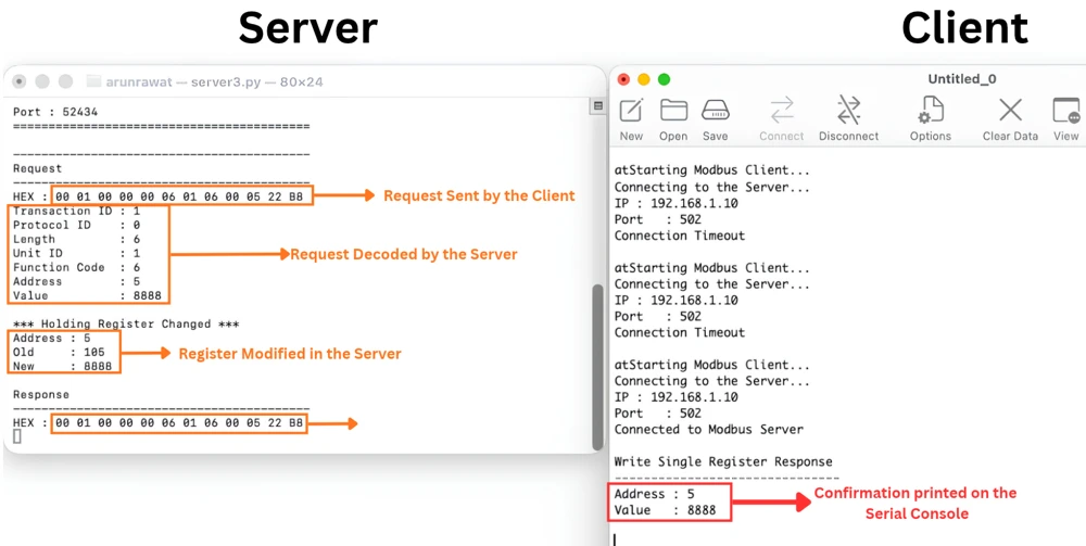
On the first button press, the client sends a request for function code 6, asking the server to write the value 8888 into register 5.
		 	case 1:
		 		MB_WriteSingleRegister(counter, 1, 5, 8888);
break;The server decodes this request, updates the register, and sends a response back. Once the client decodes this response, it prints that address 5 was written with the value 8888.
Writing Multiple Registers
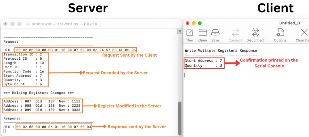
On the second button press, the client sends a request to write three registers, starting from address 7.
		 	case 2:
		 		uint16_t  regs[3] = {1111, 2222, 3333};
		 		MB_WriteMultipleRegisters(counter, 1, 7, 3, regs);
break;The server decodes the byte count as 6, which is correct for three registers, and updates each register with the new value from the client. After the update, the server sends a confirmation back, and the client prints that three registers were updated starting from address 7.
Writing a Single Coil
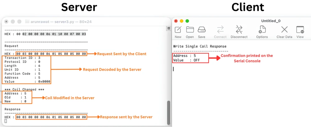
On the third press, the client requests writing a single coil.
		 	case 3:
		 		MB_WriteSingleCoil(counter, 1, 5, 0);
break;The server decodes the request and understands that the client wants to write the value 0 into coil number 5. The coil, which was earlier set to 1, is changed to 0, and the confirmation is printed on the client’s console.
Writing Multiple Coils
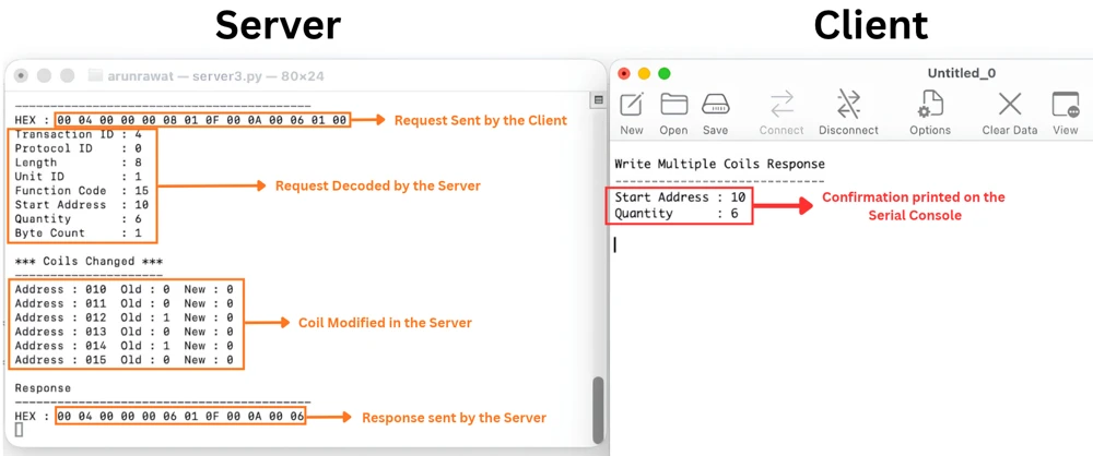
On the fourth press, the client sends a request to write six coils, starting from coil number 10.
		 	case 4:
		 		uint8_t coils[6] = {0, 0, 0, 0, 0, 0};
		 		MB_WriteMultipleCoils(counter, 1, 10, 6, coils);
break;The server updates all six coils based on the data array we sent, and the client prints the confirmation once the response arrives.
Confirming the Data with a Read Request
To confirm that all of this actually changed the data on the server, the fifth and sixth button presses send read requests for the holding registers and the coils.
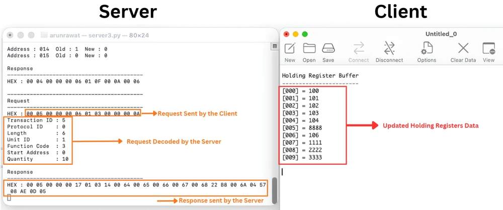
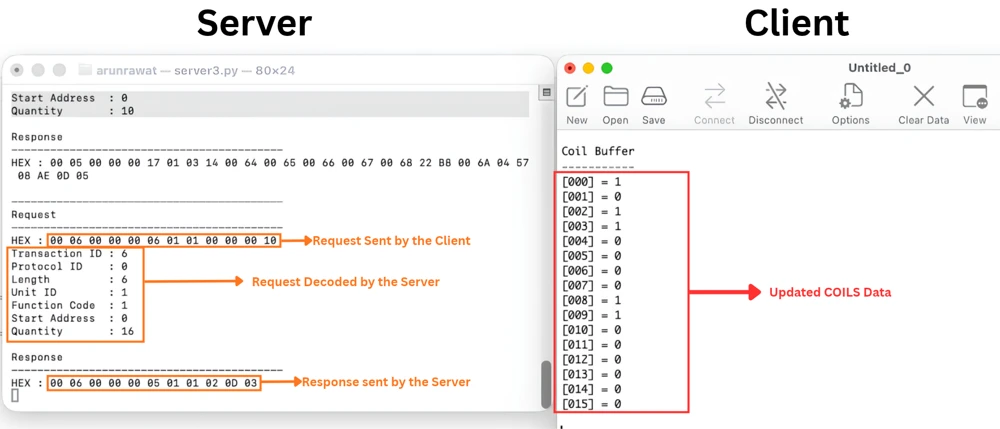
Register 5 now shows the value 8888, and registers 7 to 9 show the values we sent through the array. The coils show the same result, with coil number 5 and the last five coils reflecting the values we wrote earlier.
This confirms that our STM32 Modbus client can now both read and write data on a Modbus TCP server.
Conclusion
With this, our STM32 Modbus TCP client can now both read and write data on a remote server. We covered all four write function codes, single register, multiple registers, single coil, and multiple coils, and saw how the client decodes the server’s confirmation for each one. Reading the same data back afterward gave us a simple way to confirm that every write actually reached the server’s database.
This also brings the STM32 Modbus TCP series to a close. We started with the STM32 acting as a Modbus server, and we are now finishing with it acting as a fully functional Modbus client. Together, these two roles cover everything you need to build a Modbus TCP based application on the STM32 with LwIP. If you are building an industrial or home automation setup, these same request and parser functions can be reused directly. You only need to adjust the addresses and quantities to match your own Modbus database.
Download Project Here
Download the CubeMX project files and HAL source code — all tested on real hardware.
If you find this useful, you can support us with a Donation as well.
Browse More STM32 TCP Tutorials
STM32 Modbus TCP Server using LWIP Part 3: Writing Holding Registers (FC06 & FC16)
STM32 Modbus TCP Server Part 4: Reading Coils and Discrete Inputs (FC01 & FC02)
STM32 Modbus TCP Server using LWIP Part 5: Writing Coils (FC05 & FC15)

STM32 Modbus TCP Client using LWIP Part 6: Setting Up the Client
STM32 Modbus TCP Client using LWIP – Part 7: Reading Registers and Coils

Subscribe
Login
0 Comments
Newest

