

Home ▸ STM32 Tutorials ▸ Modbus ▸ TCP ▸
Updated On: October 18, 2026
STM32 Modbus TCP Server: Reading Coils and Discrete Inputs (FC01 & FC02)
In part 3 of this series, we added function code 6 and function code 16 to our Modbus server, so the client was able to write both single and multiple holding registers. That completed all the register based operations, reading and writing both.
In this part, we move away from registers and handle function code 1 and function code 2, which deal with coils and discrete inputs. These are 1-bit values, unlike the 16-bit registers we have been working with so far. Function code 1 lets the client read the status of a coil, and function code 2 lets the client read the status of a discrete input. We are only covering the reading part in this tutorial. Writing to coils, using function codes 5 and 15, will be covered in the next part.
This is a continuation of the same project, so I am not repeating the Ethernet or UART configuration here. If you have not gone through the earlier parts yet, go through them first. This time, there is a small CubeMX change, since we need a few new input pins for the discrete inputs. On top of that, three files need to be replaced in the project: Modbus_Database.h, Modbus_Database.c, and Modbus_Parser.c.
This is the Part 4 in the STM32 Modbus TCP Series.
Table of contents
How Coils and Discrete Inputs Work
Coils are 1-bit values, and their addresses range from 0 to 9,999. Each coil can have only two possible states: ON (1) or OFF (0). The Modbus client uses Function Code 1 (Read Coils) to read the status of one or more coils from the server.

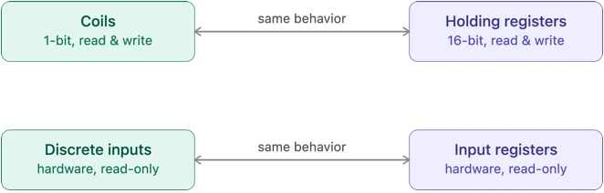
In this tutorial, we will create a small coil database inside the server and initialize it with some default values. Whenever the client sends a Read Coils request, the server will fetch the requested bits from this database and return them in the response. Coils behave similarly to holding registers, except that each coil occupies only 1-bit instead of a 16-bit register. Like holding registers, they are both readable and writable.
Discrete Inputs are also 1-bit values with addresses ranging from 10001 to 19999, but unlike coils, they are read-only. They represent the state of physical digital inputs, such as push buttons, switches, or sensors connected to the controller. The client can read their current state using Function Code 2 (Read Discrete Inputs), but it cannot modify them over the network.

To demonstrate this in our STM32 server, I have connected five physical switches to GPIO pins. Their states will be periodically sampled and stored in the discrete input table. When the client issues a Read Discrete Inputs (FC02) request, the server simply returns the current status of these switches. Since these values originate from hardware, the client has no way to change them remotely, making discrete inputs analogous to input registers, but at the single-bit level.
Wiring the Switches for Discrete Inputs
The potentiometer from the earlier parts is still connected the same way, so nothing changes there. On top of that, I have connected five more wires, which represent the five switches for the discrete inputs. All five wires share a common ground connection.
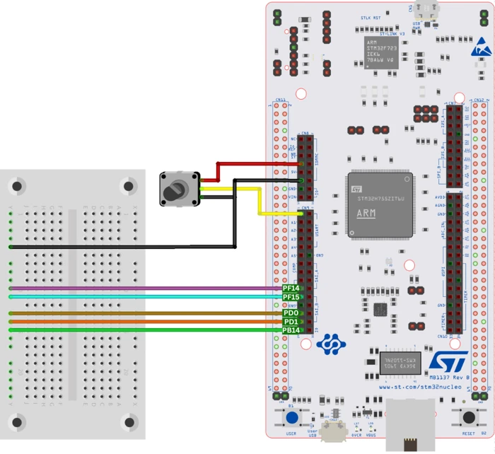
The STM32 server uses these five GPIO pins as discrete inputs. Each pin is configured as an input with an internal pull-up resistor enabled. For simplicity, these pins are referred to as Input 1 through Input 5 throughout the tutorial.
| Input | GPIO Pin | Configuration |
|---|---|---|
| Input 1 | PF14 | Input + Pull-up |
| Input 2 | PF15 | Input + Pull-up |
| Input 3 | PD0 | Input + Pull-up |
| Input 4 | PD1 | Input + Pull-up |
| Input 5 | PB14 | Input + Pull-up |
Since the internal pull-up resistor will be enabled, each input normally reads HIGH (1). However, all five pins are connected to GND using jumper wires, forcing them to read LOW (0). Disconnecting any jumper wire allows the corresponding pull-up resistor to pull the pin HIGH, effectively simulating a switch press/release.
CubeMX Setup for the Discrete Input Pins
We will continue with the project from previous part of this series. The Ethernet and UART configuration stay exactly as they were, so there is nothing to change there.
In this tutorial, we will set five pins as input: PF14, PF15, PD0, PD1, and PB14. These are the same pins used in the connection diagram above. Go to the System Core -> GPIO section, and give each of these pins a custom label, from Input1 to Input5, in the same order they are physically wired on the board.
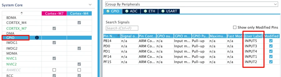
Since this is a dual core board and the Modbus TCP server runs only on the Cortex-M7 core, the GPIO context assignment for these pins needs to be set to Cortex-M7 as well. Also enable the internal pull-up for all five pins, so they read high by default unless they are pulled low manually.
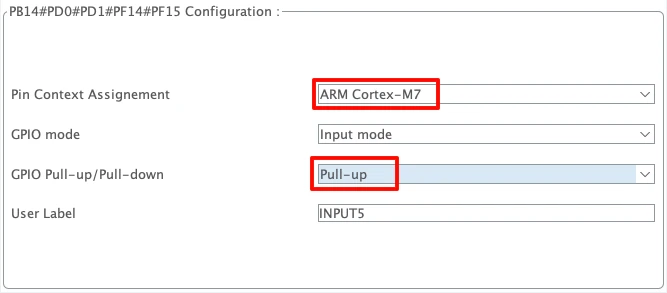
That is all we need to change in CubeMX. Click Generate Code once done.
Modbus_Parser.c Changes for FC01 and FC02
Let’s see what changes has been made in the Modbus_Database.h, Modbus_Database.c, and Modbus_Parser.c files.
Modbus_Database.h Changes
Two new counts are defined here, one for the coils and one for the discrete inputs:
#define MB_COIL_COUNT           20
#define MB_DIS_INPUT_COUNT 5The coil and discrete input arrays are also declared here as external variables, so the parser file can access them:
extern uint16_t MB_Coils[MB_COIL_COUNT];
extern uint16_t MB_DisInputs[MB_DIS_INPUT_COUNT];We are working with 20 coils in this tutorial, and 5 discrete inputs, matching the five wires from the connection diagram.
Modbus_Database.c Changes
The coils database is defined with some default values, packed into bytes:
uint16_t MB_Coils[MB_COIL_COUNT] = {
        0x12, 0x34, 0x0D
};Since we have 20 coils, and each byte can hold 8 coil bits, we need 3 bytes to store all 20 bits. That is why the array only has three entries here, even though we have defined 20 coils.
The discrete inputs database is initialized with zero, since discrete inputs are hardware based and their real value has to be read from the pins:
uint16_t MB_DisInputs[MB_DIS_INPUT_COUNT] = {0};To update this database, we use a helper function, MB_SetDiscreteInput, which sets or clears one particular bit inside one particular byte:
static void MB_SetDiscreteInput(uint16_t address, int state)
{
    uint16_t byte = address / 8;
    uint8_t bit = address % 8;

    if(state)
        MB_DisInputs[byte] |= (1 << bit);
    else
        MB_DisInputs[byte] &= ~(1 << bit);
}First, we find the byte that needs to change, then we find the bit inside that byte, and depending on the current state of the pin, we either set that bit or clear it.
This helper function is then called once for each of the five inputs, inside MB_UpdateDiscreteInputs:
void MB_UpdateDiscreteInputs(void)
{
    MB_SetDiscreteInput(0, HAL_GPIO_ReadPin(INPUT1_GPIO_Port, INPUT1_Pin));
    MB_SetDiscreteInput(1, HAL_GPIO_ReadPin(INPUT2_GPIO_Port, INPUT2_Pin));
    MB_SetDiscreteInput(2, HAL_GPIO_ReadPin(INPUT3_GPIO_Port, INPUT3_Pin));
    MB_SetDiscreteInput(3, HAL_GPIO_ReadPin(INPUT4_GPIO_Port, INPUT4_Pin));
    MB_SetDiscreteInput(4, HAL_GPIO_ReadPin(INPUT5_GPIO_Port, INPUT5_Pin));
}This function needs to be called from main.c as well, in the same place where we already call MB_UpdateInputRegisters:
extern void MB_UpdateDiscreteInputs(void);

if ((HAL_GetTick() - prevTick) > 500)
{
    prevTick = HAL_GetTick();
    MB_UpdateInputRegisters();
    MB_UpdateDiscreteInputs();
}This way, the discrete input database refreshes every 500 milliseconds, based on the current state of the switches.
MB_ProcessFunction Changes
Two new cases are added here, one for reading coils and one for reading discrete inputs:
case MB_FC_READ_COILS:
    return MB_FC01_ReadCoils(pcb, req);

case MB_FC_READ_DISCRETE_INPUTS:
return MB_FC02_ReadDisInputs(pcb, req);Everything else in this function stays the same as part 3. Any function code that does not match one of the cases still falls through to default and receives an Illegal Function exception.
MB_FC01_ReadCoils
This is a new function added to handle function code 1. It starts by extracting the starting address and the quantity of coils the client wants to read, the same way we extract these fields for the registers:
startAddr = ((uint16_t)req->Data[0] << 8) | req->Data[1];
quantity = ((uint16_t)req->Data[2] << 8) | req->Data[3];From the quantity, we calculate how many bytes we need to store the response data. Since each byte holds 8 coils, this comes down to rounding the quantity up to the nearest multiple of 8:
uint8_t byteCount = (quantity + 7) / 8;For example, 50 coils need (50+7)/8 = 7 bytes, and 48 coils need (48+7)/8 = 6 bytes.
Next comes the validation checks. The client cannot request zero coils, and it cannot request more than 2000 coils in a single request, since that limit comes directly from the Modbus standard:
if((quantity == 0) || (quantity > 2000))
return MB_SendException(pcb, req, MB_EX_ILLEGAL_DATA_VALUE);We also check the request against the size of our own database. We only have 20 coils defined, so the client cannot ask for the status of the 21st coil or beyond:
if((startAddr + quantity) > MB_COIL_COUNT)
return MB_SendException(pcb, req, MB_EX_ILLEGAL_DATA_ADDRESS);Once both checks pass, we start building the response.
The MBAP header follows the same pattern as before, except the length field is now calculated as 3 plus the byte count, the 3 accounting for 1 Byte of unit ID, 1 Byte of function code, and 1 Byte of byte count field itself:
uint16_t length = 3 + byteCount;
tx[4] = length >> 8;
tx[5] = length;The PDU carries the function code, the byte count, and then the actual coil data:
tx[7] = MB_FC_READ_COILS;
tx[8] = byteCount;Copying the coil data is a little different from copying registers, since here we are working at the bit level instead of the byte level. Before the loop starts, the response buffer is cleared, so any bit we do not explicitly set stays at 0:
memset(&tx[9], 0, byteCount);
for(i = 0; i < quantity; i++)
{
uint16_t coilAddress = startAddr + i;
uint16_t sourceByte = coilAddress / 8;
uint8_t sourceBit = coilAddress % 8;
uint16_t destByte = i / 8;
uint8_t destBit = i % 8;
if((MB_Coils[sourceByte] >> sourceBit) & 0x01)
{
tx[9 + destByte] |= (1 << destBit);
}
}Let us walk through an example. Say the client is requesting 10 coils, starting from coil number 8. On the first run of the loop, i is 0, so the coilAddress = 8. The sourceByte = 8/8 = 1 and the sourceBit = 8%8 = 0. So we look inside database byte 1, bit 0, to read the value of coil 8. The destination byte and destination bit are both 0 on this run, since we start filling the response buffer from the very first bit.
By the third run, i is 2, so the coilAddress = 10. The sourceByte = 10/8 = 1, but the sourceBit = 10%8 = 2. So we now read database byte 1, bit 2.
On the last run of this example, i is 9, so the coilAddress = 17. Here, the sourceByte = 17/8 = 2 and the sourceBit = 17%8 = 1. So we read database byte 2, bit 1.
This is how the loop steps through every coil the client requested, one bit at a time, until the entire response buffer is filled. Once the loop finishes, the length is updated, and the response is sent using tcp_write and tcp_output, same as every other function code in this server.
txLen = 9 + byteCount;
if(tcp_write(pcb, tx, txLen, TCP_WRITE_FLAG_COPY) != ERR_OK)
return ERR_MEM;
tcp_output(pcb);Below is the complete function.
static err_t MB_FC01_ReadCoils(struct tcp_pcb *pcb, MB_Request_t *req)
{
uint16_t startAddr;
uint16_t quantity;
uint16_t i;
uint8_t tx[260];
uint16_t txLen = 0;
startAddr = ((uint16_t)req->Data[0] << 8) | req->Data[1];
quantity  = ((uint16_t)req->Data[2] << 8) | req->Data[3];
uint8_t byteCount = (quantity + 7) / 8;
if((quantity == 0) || (quantity > 2000))
    return MB_SendException(pcb, req, MB_EX_ILLEGAL_DATA_VALUE);
if((startAddr + quantity) > MB_COIL_COUNT)
return MB_SendException(pcb, req, MB_EX_ILLEGAL_DATA_ADDRESS);
tx[0] = req->TransactionID >> 8;
tx[1] = req->TransactionID;
tx[2] = 0;
tx[3] = 0;
uint16_t length = 3 + byteCount;
tx[4] = length >> 8;
tx[5] = length;
tx[6] = req->UnitID;
tx[7] = MB_FC_READ_COILS;
tx[8] = byteCount;
txLen = 9;
memset(&tx[9], 0, byteCount);
for(i = 0; i < quantity; i++)
{
uint16_t coilAddress = startAddr + i;
uint16_t sourceByte = coilAddress / 8;
uint8_t sourceBit = coilAddress % 8;
uint16_t destByte = i / 8;
uint8_t destBit = i % 8;
if((MB_Coils[sourceByte] >> sourceBit) & 0x01)
{
tx[9 + destByte] |= (1 << destBit);
}
}
txLen = 9 + byteCount;
if(tcp_write(pcb, tx, txLen, TCP_WRITE_FLAG_COPY) != ERR_OK)
return ERR_MEM;
tcp_output(pcb);
return ERR_OK;
}MB_FC02_ReadDisInputs
This function handles function code 2, and it is almost identical to MB_FC01_ReadCoils. There are only two differences. The address validation checks against MB_DIS_INPUT_COUNT, which is 5 in our case, since we have five switches connected. The response also carries the function code for discrete inputs instead of coils. Everything else, including the bit-by-bit copying logic, stays the same.
static err_t MB_FC02_ReadDisInputs(struct tcp_pcb *pcb, MB_Request_t *req)
{
uint16_t startAddr;
uint16_t quantity;
uint16_t i;
uint8_t tx[260];
uint16_t txLen = 0;
startAddr = ((uint16_t)req->Data[0] << 8) | req->Data[1];
quantity = ((uint16_t)req->Data[2] << 8) | req->Data[3];
uint8_t byteCount = (quantity + 7) / 8;
if((quantity == 0) || (quantity > 2000))
    return MB_SendException(pcb, req, MB_EX_ILLEGAL_DATA_VALUE);
if((startAddr + quantity) > MB_DIS_INPUT_COUNT)
return MB_SendException(pcb, req, MB_EX_ILLEGAL_DATA_ADDRESS);
tx[0] = req->TransactionID >> 8;
tx[1] = req->TransactionID;
tx[2] = 0;
tx[3] = 0;
uint16_t length = 3 + byteCount;
tx[4] = length >> 8;
tx[5] = length;
tx[6] = req->UnitID;
tx[7] = MB_FC_READ_DISCRETE_INPUTS;
tx[8] = byteCount;
txLen = 9;
memset(&tx[9], 0, byteCount);
for(i = 0; i < quantity; i++)
{
uint16_t coilAddress = startAddr + i;
uint16_t sourceByte = coilAddress / 8;
uint8_t sourceBit = coilAddress % 8;
uint16_t destByte = i / 8;
uint8_t destBit = i % 8;
if((MB_DisInputs[sourceByte] >> sourceBit) & 0x01)
{
tx[9 + destByte] |= (1 << destBit);
}
}
txLen = 9 + byteCount;

if(tcp_write(pcb, tx, txLen, TCP_WRITE_FLAG_COPY) != ERR_OK)
	return ERR_MEM;

tcp_output(pcb);
return ERR_OK;
}That covers everything new in Modbus_Parser.c. No further changes are needed in main.c beyond the one line already mentioned above, calling MB_UpdateDiscreteInputs inside the loop.
Testing Server with Simply Modbus TCP Client
After flashing the project, open the serial terminal on the ST-Link virtual COM port at 115200 baud, the same as the earlier parts. Open Simply Modbus TCP Client and connect to the server’s IP address on port 502.
Reading coils (FC01)
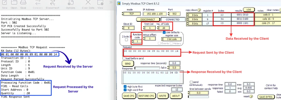
Set the function code to 1, the first coil to 1, and the quantity to 20, with the offset set to 1. This maps to a request for reading 20 coils, starting from address 0. The server log shows it received a request to read coils starting from address 0, with a quantity of 20, and the response matches exactly what we defined in the database.
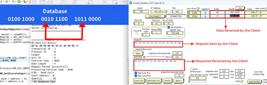
Now the client will request from a different starting point: 10 coils starting from coil number 10. The data that comes back again matches what is stored in the database at that offset.
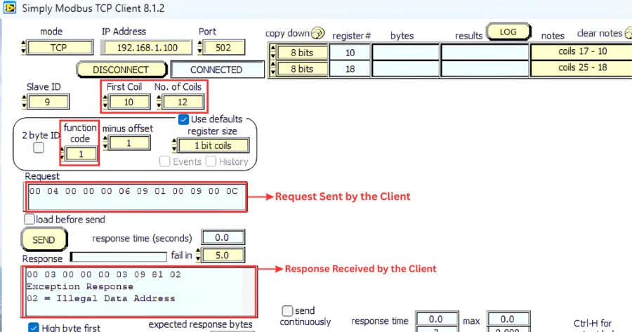
To check the exception handling, request 12 coils starting from coil number 10. Since we only have 20 coils defined, this reaches into the 21st coil, which does not exist, and the client receives an Illegal Data Address exception, exactly as expected.
Reading discrete inputs (FC02)
To read the Discrete Inputs, we will use the function code to 2, and start reading from address 10001. We will request 5 inputs in total, matching the five discrete inputs we defined.
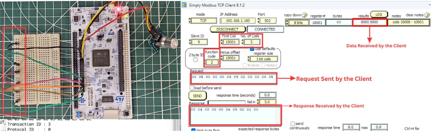
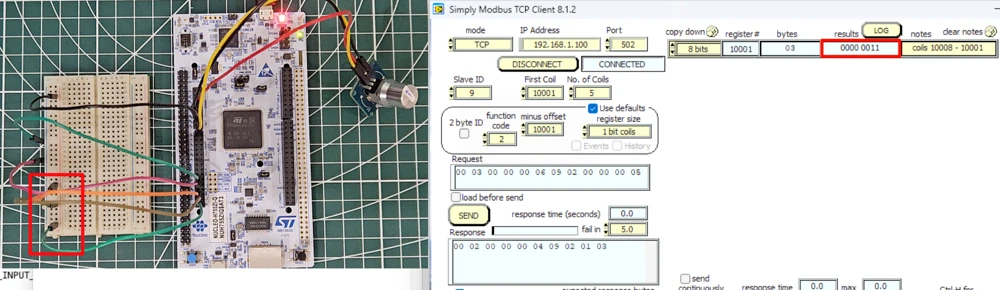
With all five wires still connected to ground, the response comes back as all zeros, meaning every switch reads low.
Disconnect the first and second wire, and send the request again. You will see that both the first and second bits reads 1. This is because the INPUT1 and INPUT2 are High now.
If you remove the common ground connection entirely, every input will read high.
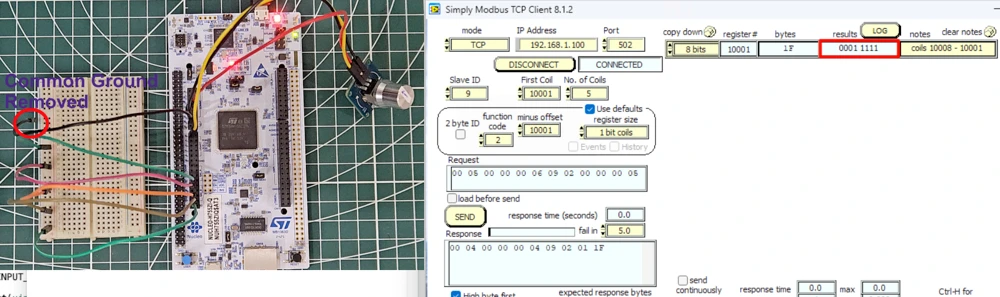
This confirms that function codes 1 and 2 are both working correctly, letting the client read the coil and discrete input data from the server.
In the next part, we will look at function codes 5 and 15, which let the client write to the coils.
Conclusion
That completes function code 1 and function code 2 for our STM32 Modbus TCP server. We now have a server that can read holding registers, input registers, coils, and discrete inputs, covering every read-based function code that the Modbus standard defines. Along the way, we also saw how bit-level data is packed and unpacked, which is a bit different from working with full 16-bit registers, but follows the same overall pattern we have used throughout this series.
In the next part, we will complete the picture by adding function codes 5 and 15, so the client can also write to the coils. Until then, feel free to experiment with different coil and discrete input counts, and try requesting data from the edges of the database to see the exception handling in action.
Download Project Here
Download the CubeMX project files and HAL source code — all tested on real hardware.
If you find this useful, you can support us with a Donation as well.
Browse More STM32 TCP Tutorials
STM32 Modbus TCP (Part 2): Read Holding & Input Registers
STM32 Modbus TCP Server using LWIP Part 3: Writing Holding Registers (FC06 & FC16)
STM32 Modbus TCP Server using LWIP Part 5: Writing Coils (FC05 & FC15)

STM32 Modbus TCP Client using LWIP Part 6: Setting Up the Client
STM32 Modbus TCP Client using LWIP – Part 7: Reading Registers and Coils

Subscribe
Login
0 Comments
Newest

