
Home ▸ STM32 Tutorials ▸ USB Tutorials ▸
Updated On: August 5, 2026
STM32 USB HID: Emulate a Mouse and Keyboard with STM32
This is Part 3 of the STM32 USB series. In Part 2, we configured the STM32 as a USB HID gamepad. We connected a joystick via ADC, wrote a custom HID report descriptor, and made Windows and macOS recognize the STM32 as a game controller without using any drivers for the same.
This time, we go further. We will use the same HID class to make the STM32 behave as a USB mouse and, separately, as a USB keyboard. Both projects are covered in this post. The mouse uses the same joystick from Part 2, and the keyboard uses a 4×4 membrane keypad.
We start from the gamepad project and build on top of it, so it is a good idea to read Part 2 first if you have not. You can go through the other tutorials of the STM32 USB series as well:
- Part 1: STM32 USB CDC: Virtual COM Port
- Part 2: STM32 USB HID Gamepad
- Part 4: STM32 USB MSC SD Card as External Drive
- Part 5: STM32 USB MSC with W25Q NOR Flash
- Part 6: STM32 USB Composite Device (CDC + HID)
- Part 7: STM32 USB HID Mouse and Keyboard Combined
- Part 8: STM32 USB Host MSC: Read & Write USB Flash Drive
- Part 9: STM32 USB HOST HID: Interface Mouse and Keyboard with STM32
- Part10: STM32 USB Host Audio Class
- Part11: STM32 USB DFU Bootloader
STM32 USB HID Mouse and Keyboard — Video Tutorial
This video covers the complete implementation of STM32 as a USB HID mouse using a joystick and ADC, and as a USB HID keyboard using a 4×4 membrane keypad. Both projects are built using STM32CubeMX and HAL, with no PC-side drivers required.
How STM32 HID Mouse and Keyboard Work
The HID class is flexible. The same class that lets an STM32 act as a gamepad can also make it behave as a mouse or a keyboard — the only difference is the report descriptor. The descriptor tells the host what kind of data it will receive and how to interpret each byte.
Both projects in this tutorial use the standard HID class in STM32CubeMX. The OS already knows how to handle mice and keyboards, so no PC-side driver is needed.
The Mouse HID Report (4 Bytes)
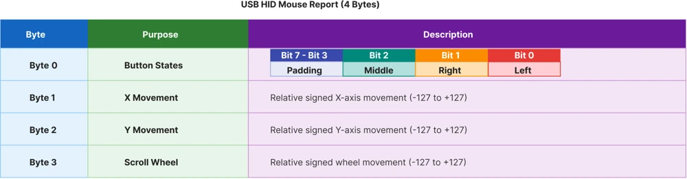
The mouse sends a 4-byte report:
- Byte 0 — Button states (3 buttons: left, right, middle — one bit each, 5 bits padding)
- Byte 1 — X-axis movement (relative, signed)
- Byte 2 — Y-axis movement (relative, signed)
- Byte 3 — Scroll wheel (relative, signed)
The key word here is relative. Unlike the gamepad, which sent absolute ADC values (0–255), the mouse descriptor uses relative data. Each value tells the OS how much the pointer should move, not where it is. So we cannot send the raw ADC value directly, instead we need to convert it into a movement delta.
The Keyboard HID Report (8 Bytes)
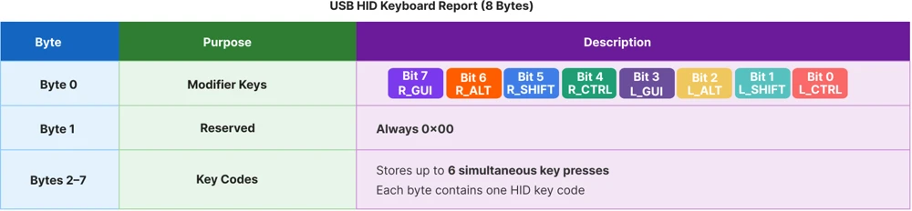
The keyboard sends an 8-byte report:
- Byte 0 — Modifier keys (8 bits: Ctrl, Shift, Alt, GUI — both left and right for each)
- Byte 1 — Reserved (always 0x00)
- Bytes 2–7 — Key codes (up to 6 simultaneous key presses)
The key codes come from the official HID Usage Tables document. For example, the number 1 key is 0x1E, letter A is 0x04, Backspace is 0x2A, and Space is 0x2C. The modifier byte works as a bitmask — setting bit 1 (0x02) activates Left Shift and setting bits 0 and 1 (0x03) activates L Shift + L Ctrl.
STM32 as a Mouse: Wiring, CubeMX, Code & Result
We will start with Emulating STM32 as a Mouse. In this case, we will read the data from the ADC Joytick connected via the ADC. The data will then be sent to the computer via the USB HID peripheral. Since we will use the mouse descriptors, the computer will see the data coming from STM32 as if it is sent by a mouse.
Wiring & connections
The image below shows the wiring diagram for the mouse project with the joystick and two additional buttons connected to the STM32 board.
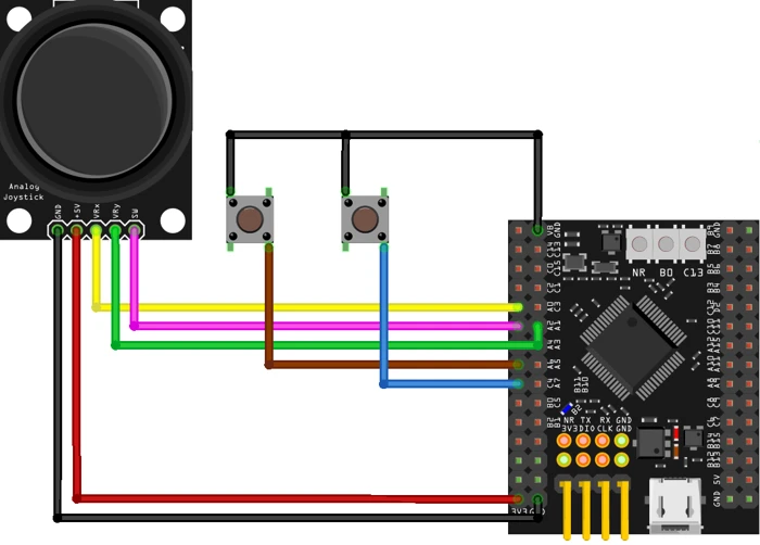
We are keeping the same joystick from the gamepad project (X axis → PA0, Y axis → PA1, button → PA2). In addition, we add two more buttons for the left and right mouse clicks.
| Signal | STM32 Pin | Function |
|---|---|---|
| Joystick VRx | PA0 | ADC1 Channel 0 (X axis) |
| Joystick VRy | PA1 | ADC1 Channel 1 (Y axis) |
| Joystick SW | PA2 | Middle click (pull-up input) |
| Left button | PA6 | Left click (pull-up input) |
| Right button | PC4 | Right click (pull-up input) |
All three button pins are pulled high by default. Pressing a button connects the pin to ground, which reads as a low signal.
CubeMX Configuration
Start by creating a new project for the STM32F446. The basic setup — SWD debug, HSE crystal, PLL at 180 MHz, and USB OTG FS in Device Only mode — is the same as what we did in Part 1. If you need a refresher on those steps, check the USB CDC tutorial.
CubeMX Configuration for HID
Once the USB peripheral is enabled, go to the Middleware section. Under USB Device, select the HID class (not Custom HID).

Under HID Parameters, there is one setting worth noting: HID_FS_BINTERVAL. This is set to 0x0A by default, which means the USB host will poll the device for new data every 10 milliseconds. That is perfectly adequate for a mouse. We will keep it as is.
Before generating the code, go to the Device Descriptor tab.
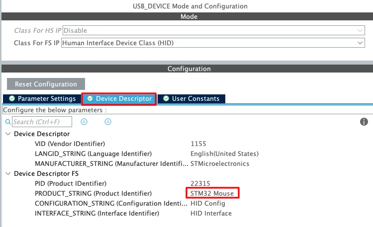
Here I have changed the product name to STM32 Mouse. So this is the name the computer will display when the device is connected. You can leave everything else at its defaults.
Next we need to make sure the USB peripheral receives exactly 48 MHz, so go into the clock tree and adjust the PLL multipliers and dividers accordingly.

We will first test our basic driver, so this configuration is enough. When this works fine, we will configure the ADC and button in CubeMX.
ADC + DMA Configuration
Now we add the actual joystick. Go back to CubeMX and configure the ADC.
Enable ADC1 with Channel 0 (PA0, X axis) and Channel 1 (PA1, Y axis).

Set the resolution to 8 bits — this matches our descriptor, which expects 8bit data.
Note:
If you are using an STM32F103 (Blue Pill), ADC resolution is fixed at 12 bits. In that case, keep it at 12 bits but map the 0–4095 range down to 0–255 in code before filling the HID buffer.
Under DMA Settings, add a DMA request for ADC1. Set the mode to Circular and the data width to Byte (since we are using 8-bit resolution).

Back in the Parameter Settings, make the following changes:
- Increase the Clock Prescaler — this slows down the conversions so DMA transfers do not interfere with the HID send loop.
- Set Number of Conversions to 2.
- Enable Scan Conversion Mode (auto-enabled when you set 2 conversions).
- Enable Continuous Conversion Mode.
- Enable DMA Continuous Requests.
- Set End of Conversion Selection to End of All Conversions — this way the DMA interrupt only fires after both channels are done, not after each individual conversion.
Under the Rank configuration, set Rank 1 to Channel 0 (X axis) and Rank 2 to Channel 1 (Y axis). Increase the Sampling Time for both ranks to keep the conversion rate manageable.

Now configure the button. Set PA2 as GPIO Input. In the GPIO settings, enable the internal Pull-up resistor for PA2.

Reminder:
If CubeMX regenerates the project, it will overwrite usbd_hid.c. Copy the descriptor before regenerating and paste it back after. Also re-apply the HID_MOUSE_REPORT_DESC_SIZE and HID_EPIN_SIZE changes in usbd_hid.h.
GPIO (Button) Configuration
We will configure 3 buttons, Left Click, Right Click and Middle Click. All the buttons will be set as inputs and will be pulled HIGH by default. When either of the button is pressed, it will be pulled LOW to the ground.
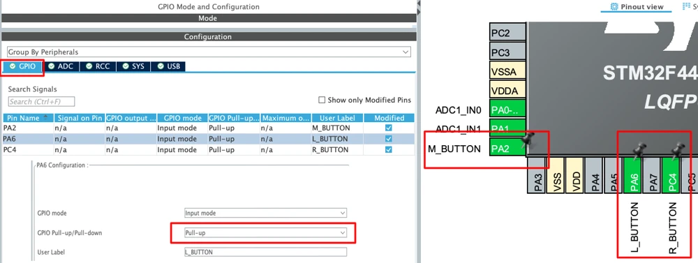
Mouse Descriptor and Code
After generating the project, open usbd_hid.c. The mouse descriptor is already generated by default — we do not need to change it for the mouse project. It already includes button support and relative X/Y movement.
Here is the complete Mouse descriptors generated by the CubeMX:
__ALIGN_BEGIN static uint8_t HID_MOUSE_ReportDesc[HID_MOUSE_REPORT_DESC_SIZE] __ALIGN_END =
{
  0x05, 0x01,        /* Usage Page (Generic Desktop Ctrls)     */
  0x09, 0x02,        /* Usage (Mouse)                          */
  0xA1, 0x01,        /* Collection (Application)               */
  0x09, 0x01,        /*   Usage (Pointer)                      */
  0xA1, 0x00,        /*   Collection (Physical)                */
  0x05, 0x09,        /*     Usage Page (Button)                */
  0x19, 0x01,        /*     Usage Minimum (0x01)               */
  0x29, 0x03,        /*     Usage Maximum (0x03)               */
  0x15, 0x00,        /*     Logical Minimum (0)                */
  0x25, 0x01,        /*     Logical Maximum (1)                */
  0x95, 0x03,        /*     Report Count (3)                   */
  0x75, 0x01,        /*     Report Size (1)                    */
  0x81, 0x02,        /*     Input (Data,Var,Abs)               */

  0x95, 0x01,        /*     Report Count (1)                   */
  0x75, 0x05,        /*     Report Size (5)                    */
  0x81, 0x01,        /*     Input (Const,Array,Abs)            */

  0x05, 0x01,        /*     Usage Page (Generic Desktop Ctrls) */
  0x09, 0x30,        /*     Usage (X)                          */
  0x09, 0x31,        /*     Usage (Y)                          */
  0x09, 0x38,        /*     Usage (Wheel)                      */
  0x15, 0x81,        /*     Logical Minimum (-127)             */
  0x25, 0x7F,        /*     Logical Maximum (127)              */
  0x75, 0x08,        /*     Report Size (8)                    */
  0x95, 0x03,        /*     Report Count (3)                   */
  0x81, 0x06,        /*     Input (Data,Var,Rel)               */
  0xC0,              /*   End Collection                       */
  0x09, 0x3C,        /*   Usage (Motion Wakeup)                */
  0x05, 0xFF,        /*   Usage Page (Reserved 0xFF)           */
  0x09, 0x01,        /*   Usage (0x01)                         */
  0x15, 0x00,        /*   Logical Minimum (0)                  */
  0x25, 0x01,        /*   Logical Maximum (1)                  */
  0x75, 0x01,        /*   Report Size (1)                      */
  0x95, 0x02,        /*   Report Count (2)                     */
  0xB1, 0x22,        /*   Feature (Data,Var,Abs,NoWrp)         */
  0x75, 0x06,        /*   Report Size (6)                      */
  0x95, 0x01,        /*   Report Count (1)                     */
  0xB1, 0x01,        /*   Feature (Const,Array,Abs,NoWrp)      */
  0xC0               /* End Collection                         */
};We begin by setting the Usage Page to Generic Desktop Controls, which contains standard HID devices such as keyboards, mice, and joysticks. The Usage is set to Mouse, which tells the host that this HID device behaves like a mouse.
Buttons — We switch to the Button Usage Page using 0x05, 0x09 and define three mouse buttons using Usage Minimum = 1 and Usage Maximum = 3. Each button occupies 1 bit, hence the logical range 0–1 (button is either pressed 1, or not pressed 0). Report Count = 3 and Report Size = 1 create a total of 3 bits for the buttons.
Padding — The buttons only uses 3 bits. A USB HID report must be byte-aligned, so we pad the remaining 5 bits in that byte with constant (non-data) bits.
X axes, Y axes and scroll wheel — We declare Usage X (0x30), Usage Y (0x31) and Usage Wheel (0x38). Then set the logical range to -127 – +127 (8-bit values), Report Size to 8 bits, and Report Count to 3. The data type is set to Relative because it should report movement delta instead of fixed coordinates.
The report is 4 bytes in total. The HID_EPIN_SIZE in usbd_hid.h is already set to 0x04, so no changes are needed there either.
main.c file
Now open main.c. We need to create the HID buffer and handle the ADC callback and button logic.
First, we declare the buffer and the ADC value array. Since the HID buffer will hold negative values (relative movement), we use int8_t:
extern USBD_HandleTypeDef hUsbDeviceFS;
int8_t HID_Buffer[4] = {0};
uint8_t ADC_Val[2];The ADC is configured in DMA mode, so we use the conversion complete callback to update the X and Y movement values. We apply a threshold check — if the joystick is tilted past a certain point, we send a fixed movement delta of ±5 pixels. Otherwise, we send 0 (no movement):
void HAL_ADC_ConvCpltCallback(ADC_HandleTypeDef *hadc)
{
if (ADC_Val[0] > 200) HID_Buffer[1] = 5;
else if (ADC_Val[0] < 55) HID_Buffer[1] = -5;
else HID_Buffer[1] = 0;
if (ADC_Val[1] > 200) HID_Buffer[2] = 5;
else if (ADC_Val[1] < 55) HID_Buffer[2] = -5;
else HID_Buffer[2] = 0;
}ADC_Val[0] is the X axis and ADC_Val[1] is the Y axis. The thresholds (200 and 55) are based on the 8-bit ADC range (0–255). Adjust these depending on your joystick’s center dead zone.
In the main loop, we handle the three button inputs and send the report every 10 ms. The left button occupies bit 0 of the button byte, the right button occupies bit 1, and the middle button (joystick press) occupies bit 2:
// In main (USER CODE BEGIN 2)
HAL_ADC_Start_DMA(&hadc1, (uint32_t *)ADC_Val, 2);
// In the while loop
while (1)
{
if (HAL_GPIO_ReadPin(L_BUTTON_GPIO_Port, L_BUTTON_Pin) == 0)
HID_Buffer[0] = 0x01; // Bit 0: left click
if (HAL_GPIO_ReadPin(R_BUTTON_GPIO_Port, R_BUTTON_Pin) == 0)
HID_Buffer[0] = 0x02; // Bit 1: right click
if (HAL_GPIO_ReadPin(M_BUTTON_GPIO_Port, M_BUTTON_Pin) == 0)
HID_Buffer[0] = 0x04; // Bit 2: middle click
USBD_HID_SendReport(&hUsbDeviceFS, (uint8_t *)HID_Buffer, 4);
HID_Buffer[0] = 0; // Reset button state after sending
HAL_Delay(10);
}We reset HID_Buffer[0] to zero after every send. This ensures the button press is registered as a single click, not held indefinitely.
One thing to note — USBD_HID_SendReport expects uint8_t *, but our buffer is int8_t. We use a typecast (uint8_t *)HID_Buffer to resolve this. The underlying memory is the same; we are just telling the compiler how to interpret it.
Here is the complete user-code section for the mouse project:
/* USER CODE BEGIN 0 */
extern USBD_HandleTypeDef hUsbDeviceFS;
int8_t HID_Buffer[4] = {0};
uint8_t ADC_Val[2];
void HAL_ADC_ConvCpltCallback(ADC_HandleTypeDef *hadc)
{
    if      (ADC_Val[0] > 200) HID_Buffer[1] =  5;
    else if (ADC_Val[0] <  55) HID_Buffer[1] = -5;
    else                       HID_Buffer[1] =  0;

    if      (ADC_Val[1] > 200) HID_Buffer[2] =  5;
    else if (ADC_Val[1] <  55) HID_Buffer[2] = -5;
    else                       HID_Buffer[2] =  0;
}
/* USER CODE END 0 */
/* USER CODE BEGIN 2 */
HAL_ADC_Start_DMA(&hadc1, (uint32_t *)ADC_Val, 2);
/* USER CODE END 2 */
/* USER CODE BEGIN 3 */
if (HAL_GPIO_ReadPin(L_BUTTON_GPIO_Port, L_BUTTON_Pin) == 0)
HID_Buffer[0] = 0x01;
if (HAL_GPIO_ReadPin(R_BUTTON_GPIO_Port, R_BUTTON_Pin) == 0)
HID_Buffer[0] = 0x02;
if (HAL_GPIO_ReadPin(M_BUTTON_GPIO_Port, M_BUTTON_Pin) == 0)
HID_Buffer[0] = 0x04;
USBD_HID_SendReport(&hUsbDeviceFS, (uint8_t *)HID_Buffer, 4);
HID_Buffer[0] = 0;
HAL_Delay(10);
/* USER CODE END 3 */Output
Flash this to the board. The STM32 should be recognized by the OS immediately as a USB mouse.
The GIF below shows the STM32 board with the joystick and buttons connected, and the cursor on the computer responding to joystick movement and button presses.

STM32 as a Keyboard: Wiring, CubeMX, Code & Result
Now we will Emulate STM32 as a Keyboard. I will connect a 4×4 keypad with STM32 and the key press from this keypad will be transmitted via the USB HID. The computer will recognise as if the data is coming from an actual keyboard.
Wiring & connections
The image below shows the wiring diagram for the Keyboard project with the 4×4 keypad connected to the STM32.
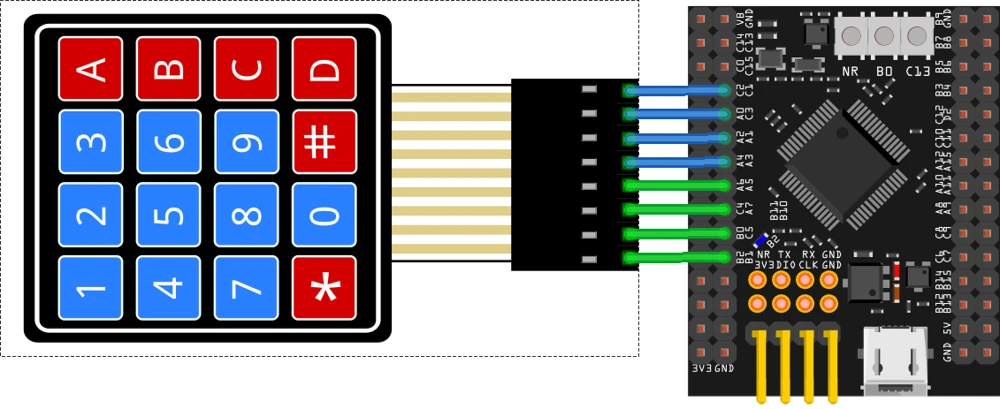
I am using a standard 4×4 membrane keypad with 4 row pins and 4 column pins. I will configure the row pins as outputs (set high by default) and the column pins as inputs with pull-up resistors.
| Keypad Pin | STM32 Pin | Mode |
|---|---|---|
| Row 1 | PB1 | Output |
| Row 2 | PC5 | Output |
| Row 3 | PA7 | Output |
| Row 4 | PA5 | Output |
| Col 1 | PA3 | Input |
| Col 2 | PA1 | Input |
| Col 3 | PC3 | Input |
| Col 4 | PC1 | Input |
All column pins use internal pull-up resistors. This ensures they read high when no button is pressed.
CubeMX Configuration
The USB HID Configuration will remain the same as what we configured during the Mouse. Although since we do not need to use ADC anymore, we will diable it. Instead we now need to configure 8 pins (4 Outputs for the Rows and 4 Inputs for the Columns).

Set the following pins as GPIO Output and label them R1–R4:
- PB1 → R1
- PC5 → R2
- PA7 → R3
- PA5 → R4
Set the following pins as GPIO Input and label them C1–C4:
- PA3 → C1
- PA1 → C2
- PC3 → C3
- PC1 → C4
Now go to GPIO Configuration. Select all four column pins, enable the Pull-up resistor for each one.
Keyboard: Descriptor Changes
After generating the project, open usbd_hid.c. CubeMX always generates the default mouse descriptor. We need to replace it with a keyboard descriptor.
The keyboard descriptor is different in a few important ways. We change the Usage from mouse (0x02) to keyboard (0x06), remove the pointer sub-collection, and restructure the data fields to match the 8-byte keyboard report format.
Here is the complete keyboard report descriptor:
__ALIGN_BEGIN static uint8_t HID_MOUSE_ReportDesc[HID_MOUSE_REPORT_DESC_SIZE] __ALIGN_END =
{
  0x05, 0x01,  /* Usage Page (Generic Desktop Ctrls) */
  0x09, 0x06,  /* Usage (Keyboard)                   */
  0xA1, 0x01,  /* Collection (Application)           */
  0x05, 0x07,  /*   Usage Page (Keyboard)            */

  /* Modifier Byte (1 Byte) */
  0x19, 0xE0,  /*   Usage Minimum (Left Ctrl = 0xE0) */
  0x29, 0xE7,  /*   Usage Maximum (Right GUI = 0xE7) */
  0x15, 0x00,  /*   Logical Minimum (0)              */
  0x25, 0x01,  /*   Logical Maximum (1)              */
  0x95, 0x08,  /*   Report Count (8)                 */
  0x75, 0x01,  /*   Report Size (1 bit)              */
  0x81, 0x02,  /*   Input (Data, Var, Abs)           */

  /* Reserved Byte (1 Byte) */
  0x95, 0x01,  /*   Report Count (1)                 */
  0x75, 0x08,  /*   Report Size (8 bits)             */
  0x81, 0x01,  /*   Input (Const, Array, Abs)        */

  /* Key Codes (6 Bytes) */
  0x19, 0x00,  /*   Usage Minimum (0x00)             */
  0x29, 0x65,  /*   Usage Maximum (0x65)             */
  0x15, 0x00,  /*   Logical Minimum (0)              */
  0x25, 0x65,  /*   Logical Maximum (0x65)           */
  0x75, 0x08,  /*   Report Size (8 bits)             */
  0x95, 0x06,  /*   Report Count (6)                 */
  0x81, 0x00,  /*   Input (Data, Array, Abs)         */
  0xC0,        /* End Collection                     */
};Let us quickly go through the important parts:
Modifier byte — Usage Minimum 0xE0 to Maximum 0xE7 covers all eight modifier keys (Left Ctrl, Left Shift, Left Alt, Left GUI, Right Ctrl, Right Shift, Right Alt, Right GUI). Each occupies 1 bit, and there are 8, so the modifier byte is exactly 1 byte.
Reserved byte — This is a constant-filled byte. It is part of the standard keyboard HID report format and must always be present, even though no data is stored here.
Key codes — Usage range 0x00 to 0x65 covers a standard 104-key keyboard layout as defined in the HID Usage Tables document. Report Count is 6, which means we can send up to 6 simultaneous key presses. The input type is Array (not Var), which is how key code bytes are typically specified for keyboards.
This descriptor has 43 bytes. Open usbd_hid.h and update these two defines:
#define HID_MOUSE_REPORT_DESC_SIZE    43U
#define HID_EPIN_SIZE 0x08UHID_EPIN_SIZE is now 8 because the full keyboard report is 8 bytes (1 modifier + 1 reserved + 6 key codes).
Keyboard: Scanning the Keypad
Keypad scanning works by activating one row at a time and then reading all four column pins. If a column reads low while a row is pulled low, the key at that intersection was pressed.
We create a scanKeypad function that handles this. It also manages two variables, modifier for the modifier byte and keycode for the active key. These variables are then placed into the HID buffer in the main loop.
uint8_t HID_Buffer[8] = {0};
uint8_t modifier = 0;
uint8_t keycode  = 0;

void scanKeypad(void)
{
    modifier = keycode = 0;

    /* Row 1 */
    HAL_GPIO_WritePin(R1_GPIO_Port, R1_Pin, GPIO_PIN_RESET);
    HAL_GPIO_WritePin(R2_GPIO_Port, R2_Pin, GPIO_PIN_SET);
    HAL_GPIO_WritePin(R3_GPIO_Port, R3_Pin, GPIO_PIN_SET);
    HAL_GPIO_WritePin(R4_GPIO_Port, R4_Pin, GPIO_PIN_SET);
    HAL_Delay(1);
    if (HAL_GPIO_ReadPin(C1_GPIO_Port, C1_Pin) == GPIO_PIN_RESET) keycode = 0x1E; // 1
    if (HAL_GPIO_ReadPin(C2_GPIO_Port, C2_Pin) == GPIO_PIN_RESET) keycode = 0x1F; // 2
    if (HAL_GPIO_ReadPin(C3_GPIO_Port, C3_Pin) == GPIO_PIN_RESET) keycode = 0x20; // 3
    if (HAL_GPIO_ReadPin(C4_GPIO_Port, C4_Pin) == GPIO_PIN_RESET) keycode = 0x04; // A

    /* Row 2 */
    HAL_GPIO_WritePin(R1_GPIO_Port, R1_Pin, GPIO_PIN_SET);
    HAL_GPIO_WritePin(R2_GPIO_Port, R2_Pin, GPIO_PIN_RESET);
    HAL_GPIO_WritePin(R3_GPIO_Port, R3_Pin, GPIO_PIN_SET);
    HAL_GPIO_WritePin(R4_GPIO_Port, R4_Pin, GPIO_PIN_SET);
    HAL_Delay(1);
    if (HAL_GPIO_ReadPin(C1_GPIO_Port, C1_Pin) == GPIO_PIN_RESET) keycode = 0x21; // 4
    if (HAL_GPIO_ReadPin(C2_GPIO_Port, C2_Pin) == GPIO_PIN_RESET) keycode = 0x22; // 5
    if (HAL_GPIO_ReadPin(C3_GPIO_Port, C3_Pin) == GPIO_PIN_RESET) keycode = 0x23; // 6
    if (HAL_GPIO_ReadPin(C4_GPIO_Port, C4_Pin) == GPIO_PIN_RESET) keycode = 0x05; // B

    /* Row 3 */
    HAL_GPIO_WritePin(R1_GPIO_Port, R1_Pin, GPIO_PIN_SET);
    HAL_GPIO_WritePin(R2_GPIO_Port, R2_Pin, GPIO_PIN_SET);
    HAL_GPIO_WritePin(R3_GPIO_Port, R3_Pin, GPIO_PIN_RESET);
    HAL_GPIO_WritePin(R4_GPIO_Port, R4_Pin, GPIO_PIN_SET);
    HAL_Delay(1);
    if (HAL_GPIO_ReadPin(C1_GPIO_Port, C1_Pin) == GPIO_PIN_RESET) keycode = 0x24; // 7
    if (HAL_GPIO_ReadPin(C2_GPIO_Port, C2_Pin) == GPIO_PIN_RESET) keycode = 0x25; // 8
    if (HAL_GPIO_ReadPin(C3_GPIO_Port, C3_Pin) == GPIO_PIN_RESET) keycode = 0x26; // 9
    if (HAL_GPIO_ReadPin(C4_GPIO_Port, C4_Pin) == GPIO_PIN_RESET) keycode = 0x06; // C

    /* Row 4 */
    HAL_GPIO_WritePin(R1_GPIO_Port, R1_Pin, GPIO_PIN_SET);
    HAL_GPIO_WritePin(R2_GPIO_Port, R2_Pin, GPIO_PIN_SET);
    HAL_GPIO_WritePin(R3_GPIO_Port, R3_Pin, GPIO_PIN_SET);
    HAL_GPIO_WritePin(R4_GPIO_Port, R4_Pin, GPIO_PIN_RESET);
    HAL_Delay(1);
    if (HAL_GPIO_ReadPin(C1_GPIO_Port, C1_Pin) == GPIO_PIN_RESET) modifier |= (1 << 1); // Left Shift
    if (HAL_GPIO_ReadPin(C2_GPIO_Port, C2_Pin) == GPIO_PIN_RESET) keycode = 0x2C;       // Space
    if (HAL_GPIO_ReadPin(C3_GPIO_Port, C3_Pin) == GPIO_PIN_RESET) keycode = 0x2A;       // Backspace
    if (HAL_GPIO_ReadPin(C4_GPIO_Port, C4_Pin) == GPIO_PIN_RESET) keycode = 0x07;       // D
}A few things worth noting here:
We reset one row pin to low while keeping the other three high. After a 1 ms delay for the pin to settle, we read all four column pins. If a column pin reads low, that key was pressed.
For Row 4, Column 1 (the * key on the keypad), we do not assign a key code. Instead, we set the modifier byte. modifier |= (1 << 1) sets bit 1, which corresponds to Left Shift in the HID Usage Tables. This lets * act as a Shift key that can be combined with other presses.
For Row 4, Column 2 (the 0 key), we map it to Space (0x2C). For Column 3 (the # key), we map it to Backspace (0x2A). These are custom mappings — the keypad does not have to match a standard layout.
Now the main loop is very simple. We call scanKeypad, place the results into the buffer, and send the 8-byte report:
while (1)
{
    scanKeypad();
    HID_Buffer[0] = modifier;  // Byte 0: modifier keys
    HID_Buffer[2] = keycode;   // Byte 2: first key code (byte 1 is reserved)
    USBD_HID_SendReport(&hUsbDeviceFS, (uint8_t *)HID_Buffer, 8);
    HAL_Delay(10);
}Note that we write the key code to HID_Buffer[2], not HID_Buffer[1]. Byte 1 is the reserved byte and must remain zero.
Output
Flash the project and open a text editor on the PC. Pressing each keypad key registers the corresponding character. Holding the * key and pressing A, B, C, or D types uppercase letters. The # key deletes the last character, and 0 inserts a space.
The GIF below shows the STM32 board with the 4×4 keypad connected, and the text editor on the PC showing keypad inputs being registered correctly, including uppercase letters using the Shift key.

STM32 USB HID Mouse & Keyboard — FAQs
Conclusion
We managed to emulate the STM32 as both a USB mouse and a USB keyboard using the standard HID device class — no PC-side drivers, no additional hardware. Just the STM32, a joystick, a few buttons, and a keypad.
The mouse project showed how relative movement data works in HID, and how the ADC values from a joystick can be converted into pointer deltas. The keyboard project showed how to modify the HID descriptor, use the HID Usage Tables to find correct key codes, and scan a 4×4 matrix keypad to send key presses to the host.
Both projects are a good starting point. The keypad used here is just for demonstration — a dedicated keyboard tutorial with a full 104-key layout is planned for the future. In the next video, we will implement the STM32 as a USB Mass Storage Class device, where the STM32 will act as a flash drive when connected to a computer.
Download STM32 USB HID Mouse and Keyboard Project
Open source CubeMX project files and HAL source code, tested on real hardware. Free to use — support the work if it helped you.
Browse More STM32 USB Tutorials
STM32 USB HID Gamepad: Configure STM32 as a Game Controller
STM32 USB Mass Storage Class: Use SD Card as External Drive
STM32 USB Mass Storage Class with W25Q NOR Flash: External Drive over SPI
STM32 USB Composite Class: CDC + HID Gamepad on One USB Port
STM32 USB HID Device: Combine Mouse and Keyboard on One Port

Subscribe
Login
0 Comments
Newest

