Home ▸ STM32 Tutorials ▸ USB Tutorials ▸
Updated On: July 18, 2026
STM32 USB Composite Class: CDC + HID Gamepad Over a Single USB Port
This is Part 6 of the STM32 USB series. In Part 5, we used the USB Mass Storage Class with a W25Q NOR Flash module connected over SPI. This time, we are doing something different. We are running two USB classes at the same time over the same physical USB port.
This is what the USB Composite Class is for. Instead of picking CDC or HID, we register both, and the host computer detects two separate USB devices from a single connection. In this tutorial, we combine CDC and HID Gamepad. The STM32 will act as a game controller and at the same time send serial data to the computer through CDC.
Before continuing with this tutorial, you need to make sure that both CDC and HID classes are working fine separately.
You can follow the other parts of this series here:
- Part 1: STM32 USB CDC: Virtual COM Port
- Part 2: STM32 USB HID Gamepad
- Part 3: STM32 USB HID Mouse and Keyboard
- Part 4: STM32 USB MSC SD Card as External Drive
- Part 5: STM32 USB MSC with W25Q NOR Flash
- Part 7: STM32 USB HID Mouse and Keyboard Combined
- Part 8: STM32 USB Host MSC: Read & Write USB Flash Drive
- Part 9: STM32 USB HOST HID: Interface Mouse and Keyboard with STM32
- Part10: STM32 USB Host Audio Class
- Part11: STM32 USB DFU Bootloader
How the USB Composite Class Works
Before jumping into code, it helps to understand what the Composite Class actually does and why extra configuration is needed compared to a single-class setup.
What Is the USB Composite Class
A standard USB device registers one class, CDC, HID, MSC, etc. The host detects it as a single device with a single function. The Composite Class changes this. It allows multiple classes to share the same USB peripheral, each with their own endpoints and interfaces. The host enumerates each class separately, so from Windows’ perspective, it sees a COM port and a game controller, both connected at once.
STM32’s USB Device Library includes a usbd_composite_builder module for exactly this purpose. It acts as a coordinator that wraps multiple class instances and presents them together in the USB descriptor.
Class IDs and Why They Matter
When using the Composite Class, each registered class gets a Class ID assigned at runtime. This ID is passed as an extra parameter to all class-specific functions. For example, USBD_CDC_SetTxBuffer, USBD_CDC_TransmitPacket, and USBD_HID_SendReport all require the Class ID when running in composite mode. The IDs are assigned in order, so the class registered first gets the lower ID and the class registered later gets the higher one.
For example, if CDC is registered first, it will get the ID 0. Then if HID is registered next, it will get the ID 1 and so on.
Endpoints Must Not Overlap
Each class uses its own set of endpoints. CDC uses three: one IN for data, one OUT for data, and one IN for control notifications. HID uses one IN endpoint. In a single-class project, you do not have to think about this much. In a composite project, all endpoints must be unique. If two classes share an endpoint address, the USB stack behaves unpredictably.
We will define all the endpoints together so to avoid any conflict between them.
STM32 Composite USB: Wiring and Connections
The CDC class needs no extra wiring since it communicates entirely over USB. The HID Gamepad part uses an analog joystick connected to two ADC channels and one GPIO pin.
The image below shows the hardware setup with the STM32F446RE and the joystick module.

The joystick has two analog outputs for the X and Y axes, and one digital output for the push-button switch.
| Joystick Pin | STM32 Pin | Function |
|---|---|---|
| VRx (X-axis) | PA0 | ADC1 Channel 0 |
| VRy (Y-axis) | PA1 | ADC1 Channel 1 |
| SW (Button) | PA2 | GPIO Input (Pull-Up) |
| VCC | 3.3V | Power |
| GND | GND | Ground |
The button pin is configured with an internal pull-up. When idle, the pin reads HIGH. When the button is pressed, it pulls LOW. That is how we will detect the button press.
STM32CubeMX Setup for Composite USB
Let’s start with configuring the project in STM32CubeMX first. Here we will setup the USB device, configure the Communication Device Class, configure the ADC and the GPIO input pin.
ADC + DMA Configuration
Enable ADC1 with Channel 0 (PA0, X axis) and Channel 1 (PA1, Y axis).

Set the resolution to 8 bits — this matches our descriptor, which expects 0–255.
Note:
If you are using an STM32F103 (Blue Pill), ADC resolution is fixed at 12 bits. In that case, keep it at 12 bits but map the 0–4095 range down to 0–255 in code before filling the HID buffer.
Under DMA Settings, add a DMA request for ADC1. Set the mode to Circular and the data width to Byte (since we are using 8-bit resolution).

Back in the Parameter Settings, make the following changes:
- Increase the Clock Prescaler — this slows down the conversions so DMA transfers do not interfere with the HID send loop.
- Set Number of Conversions to 2.
- Enable Scan Conversion Mode (auto-enabled when you set 2 conversions).
- Enable Continuous Conversion Mode.
- Enable DMA Continuous Requests.
- Set End of Conversion Selection to End of All Conversions — this way the DMA interrupt only fires after both channels are done, not after each individual conversion.
Under the Rank configuration, set Rank 1 to Channel 0 (X axis) and Rank 2 to Channel 1 (Y axis). Increase the Sampling Time for both ranks to keep the conversion rate manageable.

Now configure the button. Set PA2 as GPIO Input. In the GPIO settings, enable the internal Pull-up resistor for PA2.

Reminder:
If CubeMX regenerates the project, it will overwrite usbd_hid.c. Copy the descriptor before regenerating and paste it back after. Also re-apply the HID_MOUSE_REPORT_DESC_SIZE and HID_EPIN_SIZE changes in usbd_hid.h.
USB CDC Configuration
Even though we want to configure 2 classes in this project, CDC and HID, the CubeMX allows us to configure only one. We will configure the USB device in CSC class, and then manually add the HID Class and Composite Class later in the project.
Now, we need to do is enable the USB peripheral. Locate and enable the USB Device (FS) or USB OTG FS peripheral, depending on your board. Make sure to choose Device Only mode, since we are using STM32 as a USB device connected to a PC. Once you do this, CubeMX automatically assigns PA11 and PA12 as the USB D− and D+ lines.

Now go to the Middleware section and set the USB Device class to Communication Device Class (CDC). Under the CDC parameters, I changed both the RX and TX buffer sizes from 2048 to 1024 bytes, since we are not doing any high-throughput transfers.
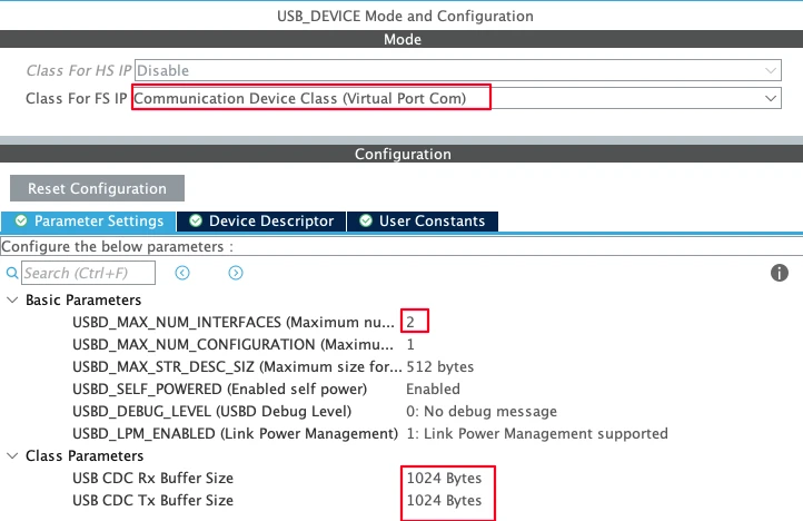
A few parameters worth noting:
- Max number of interfaces: Since we want to use 2 classes, CDC and HID, set this value to 2.
- Max number of configurations: Keep this at 1 as we only need one configuration that holds both the CDC and HID interfaces together.
- USB self-powered: Set to enabled, since the board has its own power supply and does not draw operating power from the USB bus.
Next we need to set up is the clock. Enable the external high-speed oscillator (HSE) using the onboard 8 MHz crystal, and use the PLL to scale the system clock up to 180 MHz. We also need to make sure the USB peripheral receives exactly 48 MHz. You can adjust the PLL multipliers and dividers accordingly.

STM32 Composite USB: Code and Result
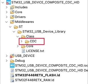
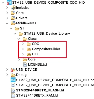
Now that we have configured the CubeMX, generate the project and import it to STM32CubeIDE. At this point the project contains only CDC class as shows in the image below.
Adding the Composite and HID Libraries
Now we need to add two additional class folders.
Composite Builder: Navigate to the STM32Cube installation folder (usually under your user directory on Windows, if not found, download from Here). Then go to Middleware > ST > STM32 USB Device Library > Class. Copy the CompositeBuilder folder and paste it into the same path inside your project.
HID class: Instead of taking the HID files from the STM32Cube installation folder, copy them from your existing HID Gamepad project. That project already has the gamepad report descriptors defined, so we get them for free.
After this, the USB Class folder in your project should contain three folders: CDC, HID, and CompositeBuilder.
Defining Composite Settings in usbd_conf.h
All composite-related definitions go into usbd_conf.h. This keeps everything in one place. Open the file and add the following inside the user code include section:
#define USE_USBD_COMPOSITE
#define USBD_CMPSIT_ACTIVATE_HID    1
#define USBD_CMPSIT_ACTIVATE_CDC    1
#define USBD_COMPOSITE_USE_IAD 1USE_USBD_COMPOSITEactivates the composite builder source file. Without this, the entireusbd_composite_builder.cis grayed out and inactive.USBD_COMPOSITE_USE_IADadds the IAD descriptor, which Windows requires to correctly identify the CDC interface pair.USBD_CMPSIT_ACTIVATE_HIDandUSBD_CMPSIT_ACTIVATE_CDCare defined to enable the HID and CDC inclusions in the composite class.
Next, define the endpoints for both classes in the same file. CDC uses three endpoints, HID uses one. The critical thing here is that no two endpoints share the same address:
#define CDC_IN_EP       0x81U  /* CDC Data IN  */
#define CDC_OUT_EP      0x01U  /* CDC Data OUT */
#define CDC_CMD_EP      0x82U  /* CDC Command  */
#define HID_EPIN_ADDR 0x83U /* HID Data IN */Notice that HID uses 0x83 instead of 0x81. In the original HID Gamepad project, the HID endpoint was 0x81. But CDC already uses that address. We move HID to the next available endpoint to avoid a conflict.
After building the project, the CDC endpoint definitions inside usbd_cdc.h and the HID endpoint inside usbd_hid.h will be grayed out. That confirms they are being picked up from the configuration file instead.
Adding Include Paths and Headers
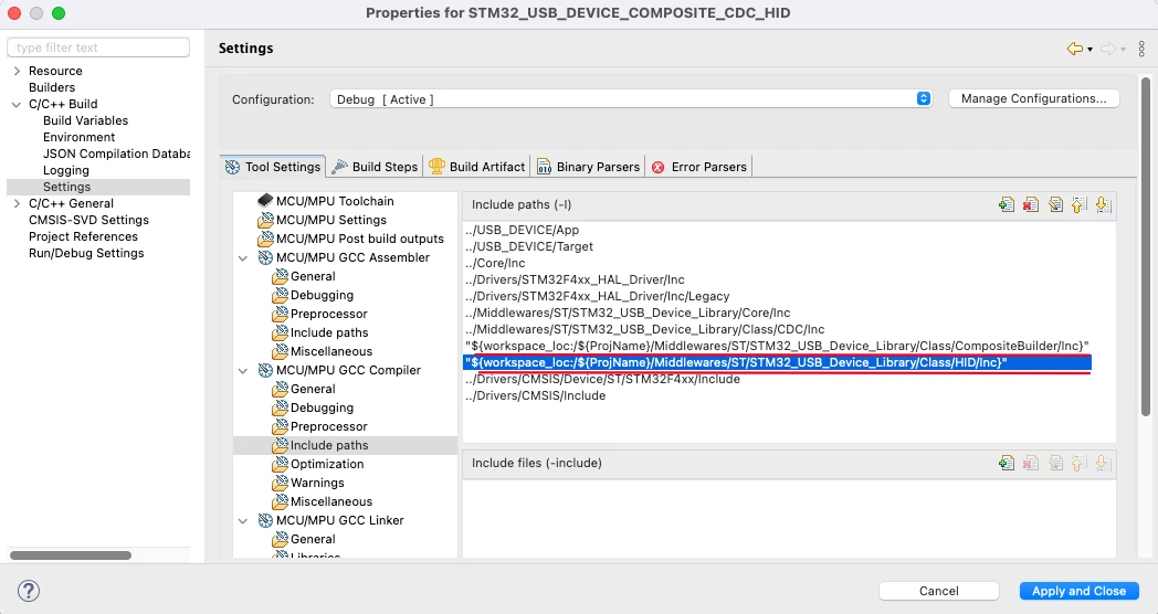
Before modifying usbd_device.c, we need to make the compiler aware of the new class folders.
Right-click the project, go to Properties > C/C++ Build > Settings > MCU Compiler > Include Paths, and add the include folders for both the Composite Builder and HID classes. The CDC folder is already included by CubeMX.
Then, at the top of usbd_device.c, add the two new header includes:
#include "usbd_composite_builder.h"
#include "usbd_hid.h"Registering Both Classes in MX_USB_DEVICE_Init
This is the main structural change. The default MX_USB_DEVICE_Init function generated by CubeMX registers the CDC class using USBD_RegisterClass. We replace that with USBD_RegisterClassComposite for both CDC and HID.
First, define the endpoint address arrays above the init function. These are passed during class registration:
uint8_t CDC_EpAddr[] = {CDC_IN_EP, CDC_OUT_EP, CDC_CMD_EP};
uint8_t HID_EpAddr[] = {HID_EPIN_ADDR};Next, define the variables to store the ClassID for the CDC and HID classes. These IDs will then be used in the respective CDC functions inside the usbd_cdc_if.c file and HID functions inside the main.c file.
uint8_t CDC_ID, HID_ID;Now here is the complete MX_USB_DEVICE_Init function:
void MX_USB_DEVICE_Init(void)
{
  if (USBD_Init(&hUsbDeviceFS, &FS_Desc, DEVICE_FS) != USBD_OK)
  {
    Error_Handler();
  }

  USBD_RegisterClassComposite(&hUsbDeviceFS, USBD_CDC_CLASS, CLASS_TYPE_CDC, CDC_EpAddr);

  USBD_RegisterClassComposite(&hUsbDeviceFS, USBD_HID_CLASS, CLASS_TYPE_HID, HID_EpAddr);

  CDC_ID = USBD_CMPSIT_SetClassID(&hUsbDeviceFS, CLASS_TYPE_CDC, 0);  // CDC -> Class ID 0
  USBD_CDC_RegisterInterface(&hUsbDeviceFS, &USBD_Interface_fops_FS);

  HID_ID = USBD_CMPSIT_SetClassID(&hUsbDeviceFS, CLASS_TYPE_HID, 0);  // HID -> Class ID 1

  if (USBD_Start(&hUsbDeviceFS) != USBD_OK)
  {
    Error_Handler();
  }
}USBD_CMPSIT_SetClassID returns the Class ID each time it is called. CDC gets ID 0 since it is registered first. HID gets ID 1 because it is the second class registered. You can store these return values in variables and use them wherever the Class ID is needed in your project.
Note that after setting the CDC class ID, we call USBD_CDC_RegisterInterface. HID does not need a separate interface registration step.
Fixing the CDC Interface Functions
When using CDC in composite mode, several functions in usbd_cdc_if.c require an extra parameter — the Class ID. The original single-class versions of these functions do not have this parameter, so they produce build errors after we switch to composite mode.
We need to update CDC_Init_FS and CDC_Transmit_FS. Pass CDC_ID as the Class ID we obtained from the usb_cdc.c file.
extern uint8_t CDC_ID;

static int8_t CDC_Init_FS(void)
{
  USBD_CDC_SetTxBuffer(&hUsbDeviceFS, UserTxBufferFS, 0, CDC_ID);  // last CDC_ID = Class ID
  USBD_CDC_SetRxBuffer(&hUsbDeviceFS, UserRxBufferFS, CDC_ID);     // last CDC_ID = Class ID
  return (USBD_OK);
}

uint8_t CDC_Transmit_FS(uint8_t* Buf, uint16_t Len)
{
  uint8_t result = USBD_OK;
  USBD_CDC_HandleTypeDef *hcdc =
      (USBD_CDC_HandleTypeDef*)hUsbDeviceFS.pClassData;
  if (hcdc->TxState != 0) {
    return USBD_BUSY;
  }
  USBD_CDC_SetTxBuffer(&hUsbDeviceFS, Buf, Len, CDC_ID);  // Class ID = CDC_ID
  result = USBD_CDC_TransmitPacket(&hUsbDeviceFS, CDC_ID); // Class ID = CDC_ID
  return result;
}Apply the same Class ID parameter to any other CDC functions that produce build errors. They all follow the same pattern.
Fixing the TX FIFO in usbd_conf.c
This is a runtime-only issue and one of the harder bugs to diagnose. The project builds cleanly, the CDC class prints data, but USBD_HID_SendReport silently blocks and never returns.
The root cause is in USBD_LL_Init inside usbd_conf.c. When CubeMX generates the project with a single CDC class, it configures the TX FIFO for only two endpoints: 0 and 1. Our composite project uses four active endpoints: three for CDC (0x01, 0x81, 0x82) and one for HID (0x83). The hardware FIFO for endpoint 3 is never allocated, so the HID transmit path stalls waiting for a buffer that does not exist.
The fix is to add FIFO allocations for endpoints 2 and 3. Replace the original CubeMX-generated FIFO lines with these:
HAL_PCDEx_SetRxFiFo(&hpcd_USB_OTG_FS, 0x80);
HAL_PCDEx_SetTxFiFo(&hpcd_USB_OTG_FS, 0, 0x20);
HAL_PCDEx_SetTxFiFo(&hpcd_USB_OTG_FS, 1, 0x20);
HAL_PCDEx_SetTxFiFo(&hpcd_USB_OTG_FS, 2, 0x20);
HAL_PCDEx_SetTxFiFo(&hpcd_USB_OTG_FS, 3, 0x20);A few things to keep in mind here:
- The RX FIFO (
0x80= 128 words) is shared across all endpoints and handles all incoming USB data, so it gets the largest share. - Each TX FIFO entry is
0x20= 32 words. - The total allocation here is 128 + 32 + 32 + 32 + 32 = 256 words.
- For the STM32F446, the combined RX + TX FIFO limit is 320 words. We are well within it.
- If you are using a different STM32 series, check the reference manual for your chip’s specific FIFO size limit before adjusting these values.
The original CubeMX-generated lines (commented out below) only cover endpoints 0 and 1, which is why HID stalls:
// Original — only covers 2 endpoints, not enough for composite:
// HAL_PCDEx_SetRxFiFo(&hpcd_USB_OTG_FS, 0x80);
// HAL_PCDEx_SetTxFiFo(&hpcd_USB_OTG_FS, 0, 0x40);
// HAL_PCDEx_SetTxFiFo(&hpcd_USB_OTG_FS, 1, 0x80);After making this change, flash the board again. The HID report will now transmit correctly alongside CDC.
Writing the Main Loop
We bring in the HID Gamepad functions from the previous project and add CDC print output alongside it. Include the required headers at the top of main.c:
#include "usbd_cdc_if.h"
#include "stdio.h"
#include "usbd_hid.h"Add the _write function to route printf through CDC:
int _write(int fd, unsigned char *buf, int len)
{
if (fd == 1 || fd == 2) {
CDC_Transmit_FS(buf, len);
}
return len;
}Declare the USB device handle, HID_ID and HID buffer:
extern USBD_HandleTypeDef hUsbDeviceFS;
extern uint8_t HID_ID;
uint8_t HID_Buffer[3] = {127, 127, 0};
uint8_t ADC_Val[2];The ADC DMA callback updates the joystick position:
void HAL_ADC_ConvCpltCallback(ADC_HandleTypeDef *hadc)
{
HID_Buffer[0] = ADC_Val[0];
HID_Buffer[1] = ADC_Val[1];
}Start the ADC DMA in the main function before the loop:
HAL_ADC_Start_DMA(&hadc1, (uint32_t *)ADC_Val, 2);The infinite loop reads the button, sends the HID report, and prints the values over CDC at the same time:
while (1)
{
HID_Buffer[2] = (HAL_GPIO_ReadPin(GPIOA, GPIO_PIN_2) == 0) ? 1 : 0;
USBD_HID_SendReport(&hUsbDeviceFS, HID_Buffer, 3, HID_ID); // Class ID = HID_ID for HID
printf("X: %d, Y: %d, B: %d\r\n", HID_Buffer[0], HID_Buffer[1], HID_Buffer[2]);
HAL_Delay(100);
}USBD_HID_SendReport takes the Class ID as the last parameter. So we pass HID_ID here.
Complete main.c
#include "main.h"
#include "usb_device.h"
#include "usbd_cdc_if.h"
#include "stdio.h"
#include "usbd_hid.h"
ADC_HandleTypeDef hadc1;
DMA_HandleTypeDef hdma_adc1;
extern USBD_HandleTypeDef hUsbDeviceFS;
extern uint8_t HID_ID;
uint8_t HID_Buffer[3] = {127, 127, 0};
uint8_t ADC_Val[2];
int _write(int fd, unsigned char *buf, int len)
{
  if (fd == 1 || fd == 2) {
    CDC_Transmit_FS(buf, len);
  }
  return len;
}
void HAL_ADC_ConvCpltCallback(ADC_HandleTypeDef *hadc)
{
  HID_Buffer[0] = ADC_Val[0];
  HID_Buffer[1] = ADC_Val[1];
}
int main(void)
{
HAL_Init();
SystemClock_Config();
MX_GPIO_Init();
MX_DMA_Init();
MX_ADC1_Init();
MX_USB_DEVICE_Init();
HAL_ADC_Start_DMA(&hadc1, (uint32_t *)ADC_Val, 2);
while (1)
{
HID_Buffer[2] = (HAL_GPIO_ReadPin(GPIOA, GPIO_PIN_2) == 0) ? 1 : 0;
USBD_HID_SendReport(&hUsbDeviceFS, HID_Buffer, 3, HID_ID);
printf("X: %d, Y: %d, B: %d\r\n", HID_Buffer[0], HID_Buffer[1], HID_Buffer[2]);
HAL_Delay(100);
}
}Output
Flash the project to the board and connect the USB cable. Open a serial console, a new CDC COM port will appear. Connect to it. You should see the X, Y, and button values printing in real time.
The image below shows the serial console with live joystick data from the CDC class.
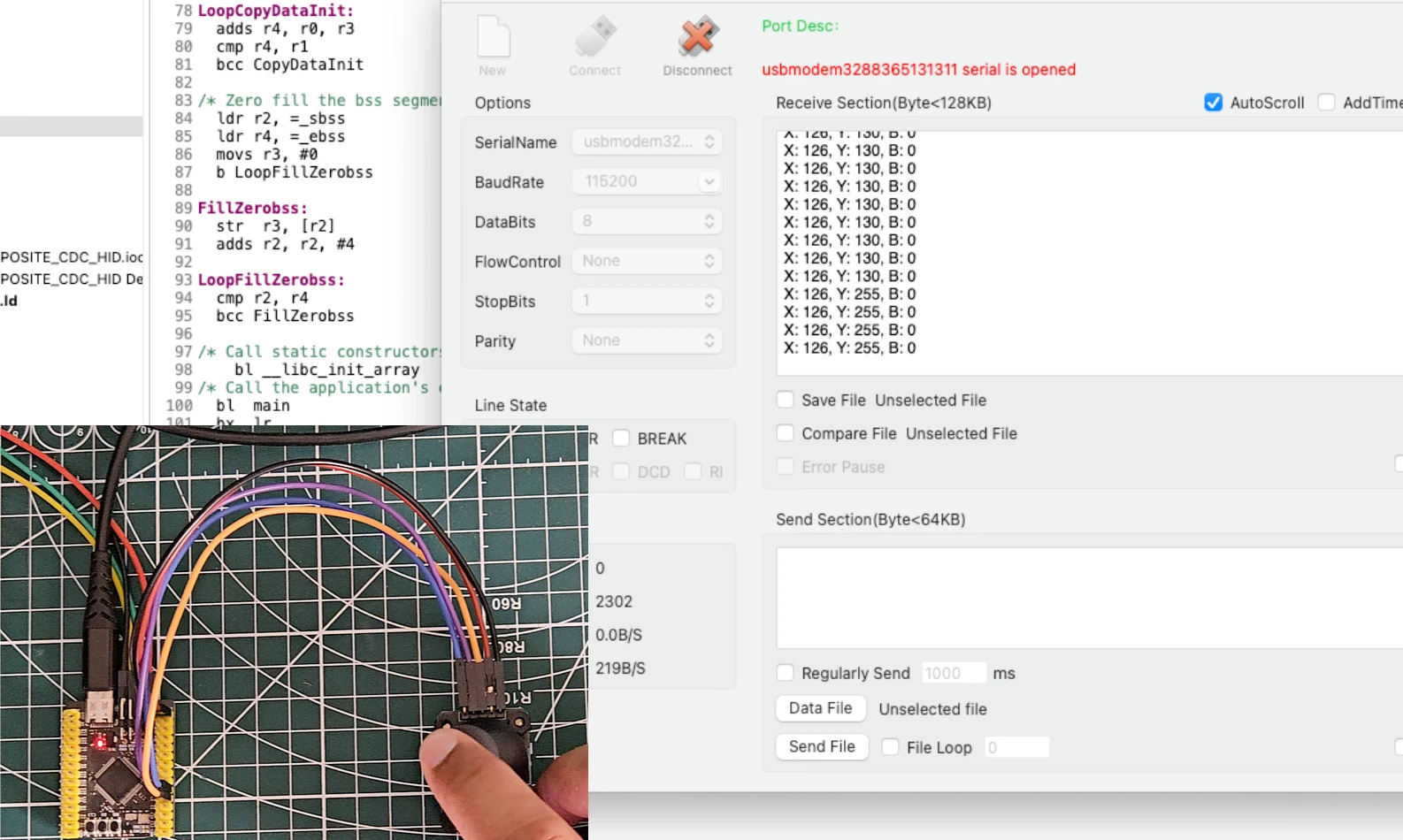
At the same time, open a Gamepad Tester in your browser. The STM32 should show up as a detected game controller. Moving the joystick will reflect on the tester axes, and pressing the button will register a button press.
The GIF below shows the gamepad tester detecting the STM32 HID gamepad with live axis movement.

Both classes are working simultaneously over a single USB connection.
STM32 USB Composite Class (CDC + HID) — Video Tutorial
This video demonstrates how to create a USB Composite Class device on STM32 by combining CDC (Virtual COM Port) and HID functionality into a single USB connection.
STM32 USB Composite Class — FAQs
Conclusion
In this tutorial, we set up the STM32 USB Composite Class by combining CDC and HID Gamepad on a single USB port. We covered everything from bringing in the composite library files, defining endpoints without conflicts, registering both classes in the correct order, fixing the TX FIFO configuration, and updating the CDC interface functions for composite mode.
The result is an STM32 that appears on the host as both a serial port and a game controller at the same time, but using just one USB cable.
Check out the rest of the STM32 USB series for more class implementations. In Part 7, we will look at combining Mouse and Keyboard inside the same HID class using a shared USB connection.
Download STM32 USB Composite CDC + HID Project
Complete STM32CubeMX project and HAL source code demonstrating a USB Composite Device with both CDC (Virtual COM Port) and HID interfaces. The project includes USB descriptors, endpoint configuration, composite class registration, HID report handling, and bidirectional CDC communication. Free to use — support the work if it helped you.
Browse More STM32 USB Tutorials
STM32 USB HID Gamepad: Configure STM32 as a Game Controller
STM32 as USB Mouse and Keyboard — HID Device Implementation
STM32 USB Mass Storage Class: Use SD Card as External Drive
STM32 USB Mass Storage Class with W25Q NOR Flash: External Drive over SPI
STM32 USB HID: Combine Mouse and Keyboard on One Port

Subscribe
Login
0 Comments
Newest
