
Home ▸ Uncategorized ▸
Updated On: September 7, 2026
CANopen with STM32: Understanding the Object Dictionary
This is Part 3 of the CANopen with STM32 series. In Part 2, we configured the CAN peripheral on STM32, added the I-CUBE-CANOPEN library by emotas, and got our board communicating as a CANopen node over TSMaster.
In this tutorial, we will look at the object dictionary, the part of a CANopen node that actually holds its data. We will go through how it is structured, what kind of objects it can store, and then add a custom object to it using CANopen Device Designer.
I am using the same STM32H562 project from Part 2, and I will continue building on it for the rest of this series.
This is the 3rd Part in the STM32 CANopen series. You can check the other tutorials below:
CANopen with STM32: Understanding the Object Dictionary — Video Tutorial
This video walks through the CANopen object dictionary on STM32 — how it is structured into the communication, device, and application profiles, and how the variable, array, record, and domain object types work. We then use CANopen Device Designer to add a custom array object and test it live with TSMaster over SDO.
Table Of Contents
What Is the CANopen Object Dictionary
The object dictionary is the database that connects CANopen communication with our STM32 application. Every piece of data inside it is addressed using an index and a subindex, and each index represents one object that stores information about the device or the application.
Think of it as the single point of contact between the CAN bus and our code. When another node on the network wants to read a value from our STM32, such as a temperature reading or a motor speed, it does not call a function or access memory directly. Instead, it sends an SDO or PDO message referencing a specific index and subindex, and the CANopen stack looks up that address inside the object dictionary and returns whatever value is stored there. Writing works the same way in reverse: the master sends the new value along with the index and subindex, and the stack updates that location.
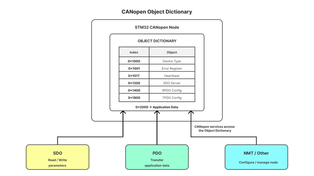
This is what makes CANopen devices interchangeable across different vendors and tools. As long as two devices agree on what a particular index and subindex represent, it does not matter what microcontroller, compiler, or internal data structure either side is using. The object dictionary acts as a common interface that sits between our application code and the CANopen communication layer. Every service in CANopen, whether it is an SDO, a PDO, or an emergency message, ultimately reads from or writes to it.
For our STM32 project, the I-CUBE-CANOPEN library has already set up this database for us, with a large set of default objects. Our task in this tutorial is to understand how it is organized, and then extend it with objects of our own.
How the Object Dictionary Is Structured
The index area is 16 bits wide, so it ranges from 0x0000 to 0xFFFF. However, we only need to work within three sections of this range.
- Communication profile (0x1000–0x1FFF): This section holds everything related to CANopen communication itself, such as the node ID, baud rate, PDO and SDO configuration, and heartbeat settings. It defines how the device communicates over CANopen.
- Application profile (0x2000–0x5FFF): Also called the manufacturer-specific profile. This is where the manufacturer stores data related to the actual application, such as motor speed, temperature, or sensor readings. This is the section we will use for the rest of this series.
- Device profile (0x6000–0x9FFF): This section defines standardized objects for a particular class of device. For example: If three different manufacturers each built a device with a temperature sensor and used three different addresses for it, other devices on the network would have no consistent way to read that sensor. By following the device profile, all three can use the same standard address in the device profile, which makes devices from different manufacturers work together on the same network.
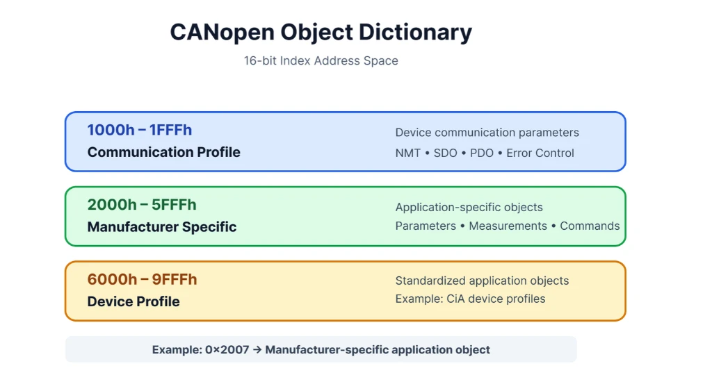
In short, the communication profile defines how CANopen communication works, the device profile defines standardized objects for a class of device, and the application profile defines the device’s own application data.
Index and Subindex Types
The object dictionary supports four object types.
- Variable: It stores a single value, and therefore it only has one subindex, and that subindex is always 0.
- Array: It is a collection of elements, therefore it can have multiple subindexes. Subindex 0 always stores the number of entries. If an array has three entries, subindex 0 holds the value 3, and the entries themselves are stored at subindex 1, 2, and 3.
- Record: It is similar to an array, but a collection of different data types with different meanings. Subindex 0 still stores the number of entries, but each entry can use a different data type. For example, one entry could be 8 bits and another 16 bits, something an array cannot do.
- Domain: It is different from the other three, since it does not represent a fixed value or a fixed set of subindexes. Instead, it represents a block of memory of variable size, which can be used to store larger, unstructured data, such as firmware images during a bootloader update. We will not use domains in this tutorial, but it is worth knowing they exist alongside the other three types.
Exploring the Default Object Dictionary in STM32CubeIDE
Before adding anything new, let’s look at the default object dictionary that is provided by I-CUBE-CANOPEN library.
Go to Middleware -> Third_Party -> emotas_CANopen -> emotas -> Config folder, and open emotas_CANopen_Slave_doc.txt. This file lists every object already configured in the project.
For example, Index 0x1000 is Device Type, 0x1001 is Error Register, 0x1005 is COB-ID Sync, and so on.
Each entry lists its data type, object code, default value, access type, and PDO mapping. Below is the entry at the index 0x1000.
Index:       0x1000 - Device type
DataType:    UNSIGNED32
ObjectCode:  Variable
  DefaultValue: 0
  AccessType:   ro
PDOMapping: 0- The
DataTypetells us what kind of value the object stores, for exampleUNSIGNED32. - The
ObjectCodetells us whether it’s a variable, array, record, or domain. DefaultValueis the value stored into this object be default. It is currently 0.AccessTypetells us whether we can read or write the object, andromeans the object is only readable. Master can not modify this object.PDOMappingtells CANopen whether this object can be packed into a PDO, and 0 means it currently can’t. We will cover PDO mapping properly when we get to PDOs later in this series.
The array at index 0x1016 (Consumer Heartbeat Time) is a good working example. Below is the entry from emotas_CANopen_Slave_doc.txt.
Index:       0x1016 - Consumer Heartbeat Time
DataType:    UNSIGNED32
ObjectCode:  Array
  Sub:          0x00 - Highest sub-index supported
  DataType:     UNSIGNED8
  DefaultValue: 3
  AccessType:   const
  PDOMapping:   0
  Sub:          0x01 - Consumer Heartbeat Time 1
  DataType:     UNSIGNED32
  DefaultValue: 0x10000
  AccessType:   rw
PDOMapping: 0- The
ObjectCodehere is set to Array, since this object needs to hold more than one value. A CANopen node can monitor the heartbeat of several other nodes at the same time, and a single variable would not be enough to hold all of that information. Sub 0x00, labeled “Highest sub-index supported” is the subindex that always exists on an array, and itsDefaultValueis 3. This means that this node can monitor up to three other nodes. ItsAccessTypeisconst, so this count cannot be changed at runtime, only the entries below it can.Sub 0x01is the first of those three entries. ItsDataTypeisUNSIGNED32, since it stores a 32-bit value. ItsDefaultValueis0x10000and theAccessTypeisrw. This mean that the subindex is both readable and writable by the master.Sub 0x02andSub 0x03follow the same pattern.
If you scroll to the bottom of emotas_CANopen_Slave_doc.txt, the last entry in the communication profile is at 0x1A03, and the application profile begins right after it, with seven default objects already defined.
These seven objects sit at indexes 0x2000 through 0x2006, and each one is a plain variable of a different data type: I_U8, I_U16, I_U32, I_I8, I_I16, I_I32, and I_R32, covering unsigned and signed integers of various widths, along with a single-precision floating-point value.
Index:       0x2000 - U8
DataType:    UNSIGNED8
ObjectCode:  Variable
  Sub:          0x00 - U8
  DataType:     UNSIGNED8
  AccessType:   rw
  PDOMapping:   1

Index:       0x2001 - U16
DataType:    UNSIGNED16
ObjectCode:  Variable
  Sub:          0x00 - U16
  DataType:     UNSIGNED16
  AccessType:   rw
  PDOMapping:   1

Index:       0x2002 - U32
DataType:    UNSIGNED32
ObjectCode:  Variable
  Sub:          0x00 - U32
  DataType:     UNSIGNED32
  AccessType:   rw
  PDOMapping:   1

Index:       0x2003 - I8
DataType:    INTEGER8
ObjectCode:  Variable
  Sub:          0x00 - I8
  DataType:     INTEGER8
  AccessType:   rw
  PDOMapping:   1

Index:       0x2004 - I16
DataType:    INTEGER16
ObjectCode:  Variable
  Sub:          0x00 - I16
  DataType:     INTEGER16
  AccessType:   rw
  PDOMapping:   1

Index:       0x2005 - I32
DataType:    INTEGER32
ObjectCode:  Variable
  Sub:          0x00 - I32
  DataType:     INTEGER32
  AccessType:   rw
  PDOMapping:   1

Index:       0x2006 - R32
DataType:    REAL32
ObjectCode:  Variable
  Sub:          0x00 - R32
  DataType:     REAL32
  AccessType:   rw
PDOMapping: 1They exist mainly as ready-made examples of each basic data type, so we can read and write them right away without configuring anything new. This is the range we are going to extend, by adding our own object right after it, at index 0x2007.
Adding a Custom Object with Device Designer
To add new objects, we use CANopen Device Designer, which comes bundled with the emotas library, under the Utilities folder, packaged separately for Linux and Windows.
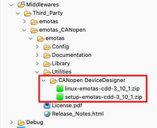
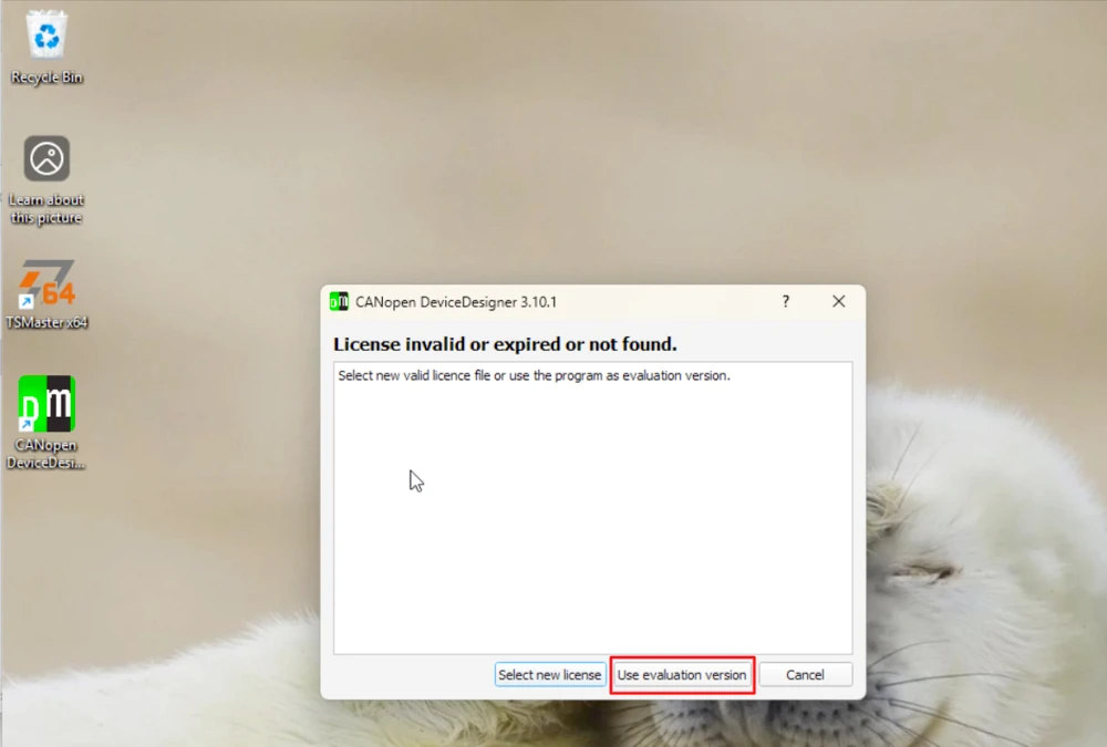
I am running Windows inside a virtual machine, so I extracted the Windows package there and installed it. The tool asks for a license file on first launch. Since we don’t have one, we continue with the evaluation version.
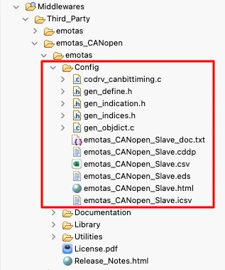
Any project generated by Device Designer follows the same file structure as the config folder inside our STM32 project, with the same define.h, indices.h, and objdict.c files. This is what lets us build a new object separately and merge it into our existing project afterward.
We cannot, however, open and regenerate our existing project directly, since it already has 36 objects defined, and the evaluation version refuses to generate files once a project gets past a certain complexity. So instead of touching our existing project inside the tool, we create a brand new, minimal project here, and add only the object we need to it.
In this new project, add an object at index 0x2007, and set its type to Array. I named it My Array.
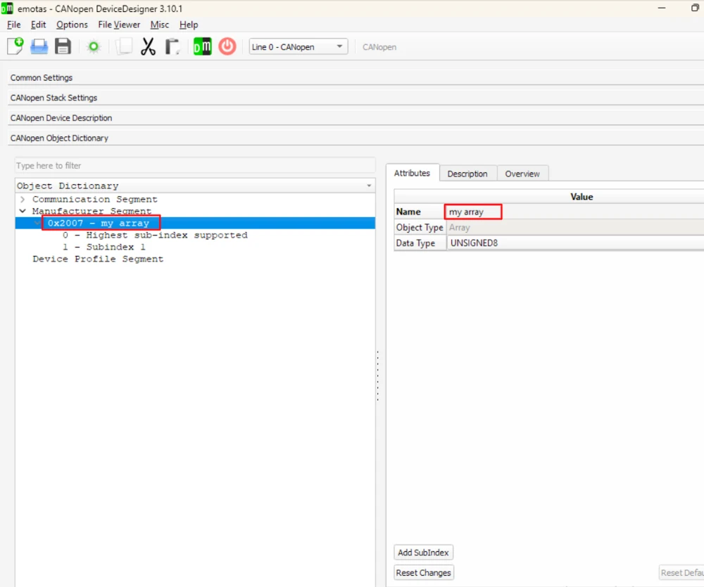
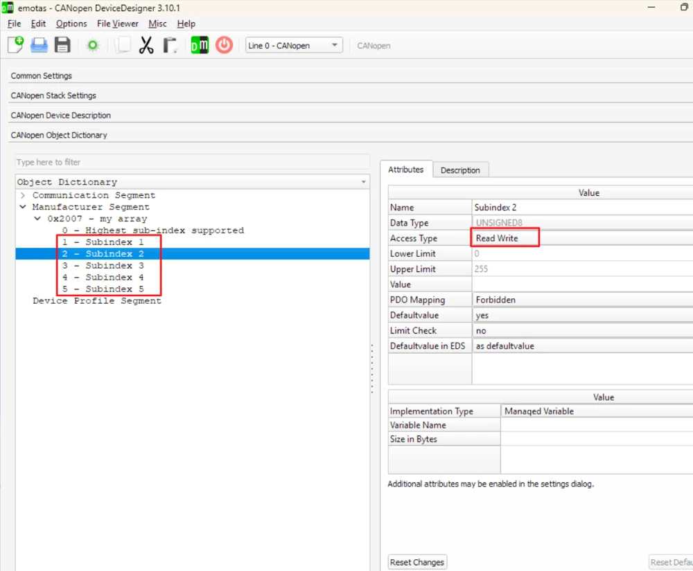
By default, a new array has two subindexes: subindex 0 for the entry count, and subindex 1 for the first value. Set subindex 1’s access type to read-write, then increase the total subindex count to 5, so subindexes 1 through 5 all use the same read-write configuration.
Once generated, this new project produces the same file set as our STM32 project: define.h, indices.h, and objdict.c. The generated project structure is shown below:
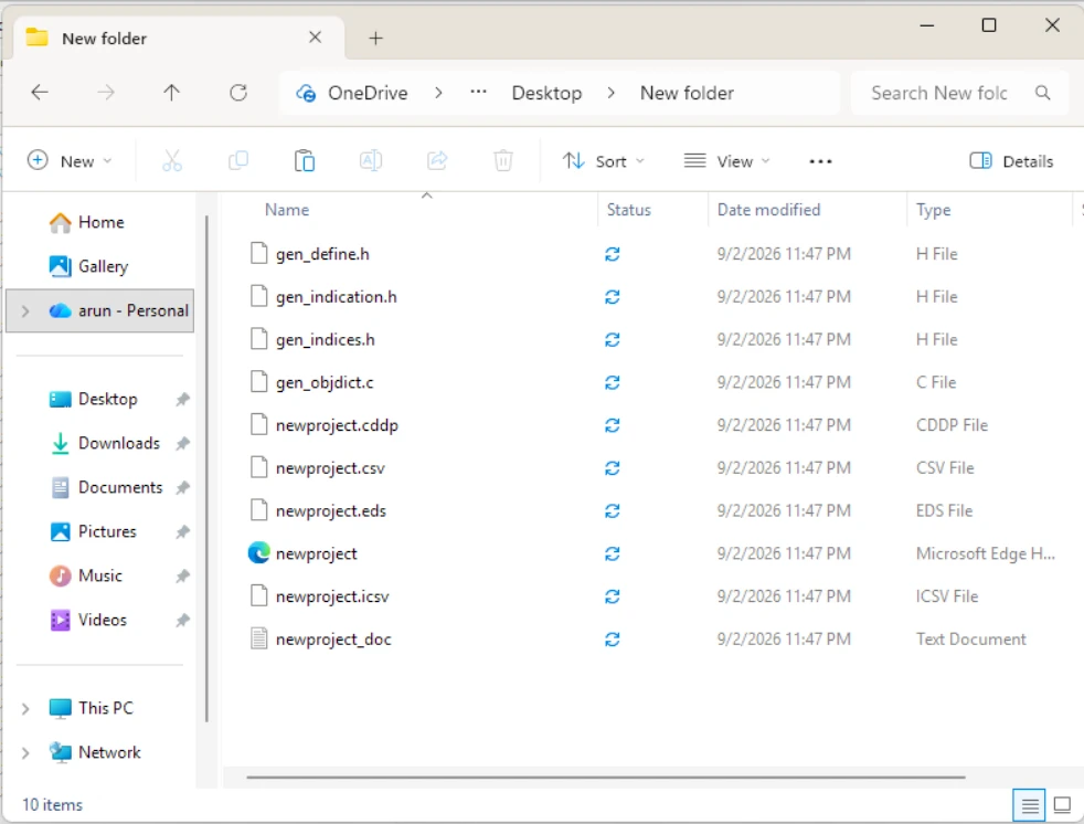
We now take the relevant pieces from each of these generated files and merge them into our existing project by hand.
Updating define.h
The object count needs to reflect the new total. Our project had 36 objects, and after adding this array, it becomes 37. This is written as an addition rather than a plain number, so it stays clear where the extra object came from:
#define CO_OBJECTS_LINE_0_CNT	36+1u
#define CO_OBJECT_COUNTS 36+1uI am also changing the node from 127 to 1:
#define CO_NODE_IDS 0x01Nothing else in this file needs to change.
Updating indices.h
This file gives every index a readable name. Our project already defines entries up to 0x2006, so we add 0x2007, copied from the newly generated project:
.............
#define I_I32                    	0x2005u
#define I_R32                    	0x2006u
#define I_MY_ARRAY               	0x2007u
#define  S_SUBINDEX_1             	0x1u
#define  S_SUBINDEX_2             	0x2u
#define  S_SUBINDEX_3             	0x3u
#define  S_SUBINDEX_4             	0x4u
#define  S_SUBINDEX_5             	0x5u
#define S_NUMBER_OF_ENTRIES 0x0uThis gives our new object a name we can reference in code, instead of writing 0x2007 everywhere.
Updating objdict.c
This is where most of the changes live, so it’s worth going through carefully.
The object counts at the top of the file increase first. CO_OD_ASSIGN_CNT goes up by 1 for the new object, and CO_OBJ_DESC_CNT goes up by 6, one descriptor for each of the six subindexes:
#define CO_OD_ASSIGN_CNT 36+1u
#define CO_OBJ_DESC_CNT 148+6u // 6 descriptors (1+5)Next, the storage array for our managed variables. Subindex 0 is constant, since it just reflects the entry count, while subindexes 1 through 5 are managed variables. All five are 8-bit unsigned integers, so we add five elements to od_u8:
static UNSIGNED8 CO_STORAGE_CLASS od_u8[10+5]; // 5 subIndxesIf your subindexes used a different data type, you’d add them to the matching array instead, such as od_u16 or od_u32.
Subindex 0 is a contact and hence its value needs to exist in the constant array od_const_u8. It stores the entry count, which is 5, and this value already exists in the array, at position 4:
static CO_CONST UNSIGNED8 CO_CONST_STORAGE_CLASS	od_const_u8[7] = {
	(UNSIGNED8)0u,  //0
	(UNSIGNED8)3u,  //1
	(UNSIGNED8)4u,  //2
	(UNSIGNED8)2u,  //3
	(UNSIGNED8)5u,  //4
	(UNSIGNED8)254u, //5
(UNSIGNED8)6u}; //6If the value you need isn’t already there, you need to extend this array and add it as a new element.
Now, od_description, which holds the descriptor for every object. Copy the six descriptors generated for our array, subindex 0 through 5, and add them to the end of this array:
	{ (UNSIGNED8)0u, CO_DTYPE_U8_CONST , (UNSIGNED16)4u, CO_ATTR_NUM | CO_ATTR_READ | CO_ATTR_DEFVAL,  (UNSIGNED16)4u},/* 0x2007:0*/
	{ (UNSIGNED8)1u, CO_DTYPE_U8_VAR   , (UNSIGNED16)1u, CO_ATTR_NUM | CO_ATTR_READ | CO_ATTR_WRITE | CO_ATTR_DEFVAL,  (UNSIGNED16)0u},/* 0x2007:1*/
	{ (UNSIGNED8)2u, CO_DTYPE_U8_VAR   , (UNSIGNED16)2u, CO_ATTR_NUM | CO_ATTR_READ | CO_ATTR_WRITE | CO_ATTR_DEFVAL,  (UNSIGNED16)0u},/* 0x2007:2*/
	{ (UNSIGNED8)3u, CO_DTYPE_U8_VAR   , (UNSIGNED16)3u, CO_ATTR_NUM | CO_ATTR_READ | CO_ATTR_WRITE | CO_ATTR_DEFVAL,  (UNSIGNED16)0u},/* 0x2007:3*/
	{ (UNSIGNED8)4u, CO_DTYPE_U8_VAR   , (UNSIGNED16)4u, CO_ATTR_NUM | CO_ATTR_READ | CO_ATTR_WRITE | CO_ATTR_DEFVAL,  (UNSIGNED16)0u},/* 0x2007:4*/
{ (UNSIGNED8)5u, CO_DTYPE_U8_VAR , (UNSIGNED16)5u, CO_ATTR_NUM | CO_ATTR_READ | CO_ATTR_DEFVAL, (UNSIGNED16)0u},/* 0x2007:5*/Look closely at the first line. The 4u in the third and last fields is not “4 entries” — it’s an index pointing into od_const_u8. The stack fetches whatever value is stored at that position, which is 5, so this descriptor correctly reports 5 entries. If you get this index wrong, reading subindex 0 will return the wrong count, even with a correct array behind it.
Last, od_assign, which tells the stack where each object’s descriptors start:
{ 0x2007u, 6u, 5u, CO_ODTYPE_ARRAY, 148u },The 148u is the offset where this object’s six descriptors begin in od_description. This always has to line up with where the previous object’s descriptors end. If you add another object after this one, calculate its offset the same way, based on how many descriptors came before it, rather than copying the offset straight from a freshly generated project.
Add the same entries to emotas_CANopen_Slave_doc.txt as well, so the documentation matches the code:
Index:       0x2007 - my array
DataType:    UNSIGNED8
ObjectCode:  Array
  Sub:          0x00 - Highest sub-index supported
  DataType:     UNSIGNED8
  DefaultValue: 5
  AccessType:   ro
  PDOMapping:   0
  Sub:          0x01 - Subindex 1
  DataType:     UNSIGNED8
  AccessType:   rw
  PDOMapping:   0
.......Testing the New Object with TSMaster
We can confirm if the new object works, by reading and writing it with SDO commands.
An SDO request from master to slave always uses ID 0x600+nodeID, and the response from slave to master uses ID 0x580+nodeID. With our node ID set to 1, the master sends on 0x601, and the node responds with 0x581.
To read an object, send command byte 0x40, followed by the the index in little-endian order, the subindex, and 4 zero-bytes to fill an 8-byte frame.
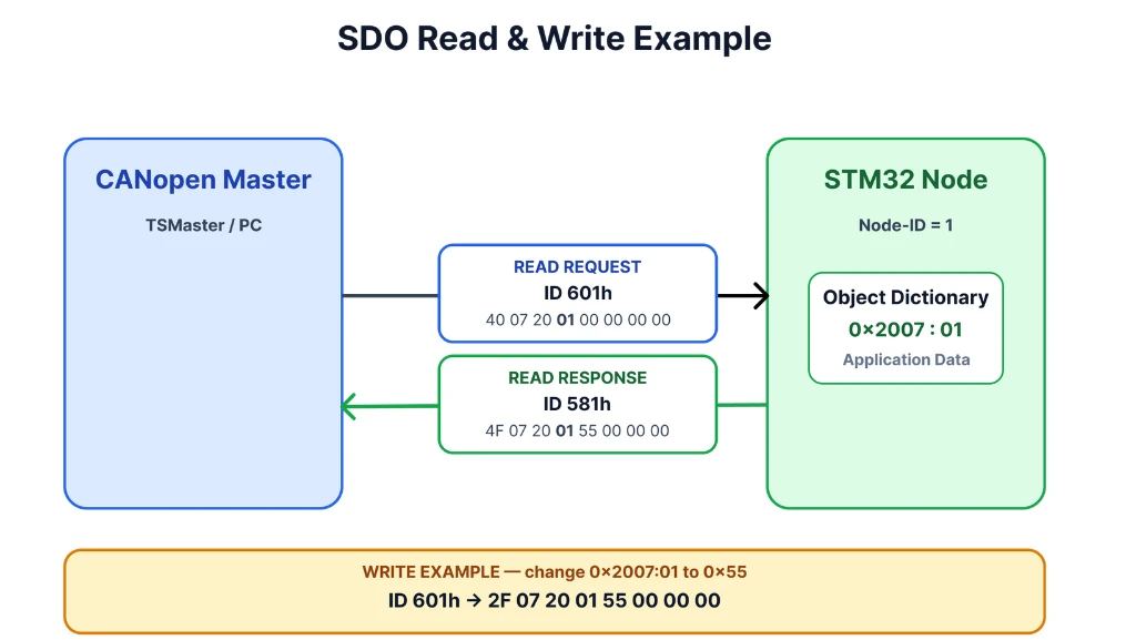
For example, in order to read subindex 1 at 0x2007 we will send the command 40 07 20 01 00 00 00 00. The STM32 Node should respond with 1 byte of data using 4F 07 20 01 55 00 00 00, where 0x55 is the data stored at 0x2007:01.
Reading Subindex 0
Let’s start by reading subindex 0. This is where the “Highest sub-index supported” is stored. Since we have 5 entries inside the index 0x2007, the STM32 node should respond with value 5.
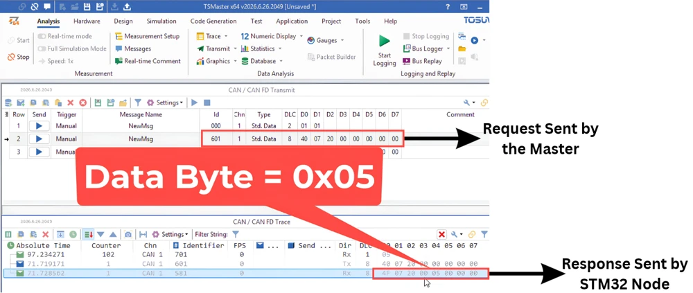
STM32 Node responds with data value 5 implying that there are 5 entries in the index 0x2007. This means our newly created object is working fine. Let’s test more subindexes now.
Writing Subindex 1
To write the data we use command byte 0x2F for a one-byte write, followed by the index, subindex, and the data byte. I am going to write 0x67 to subindex 1 as shown in the image below:
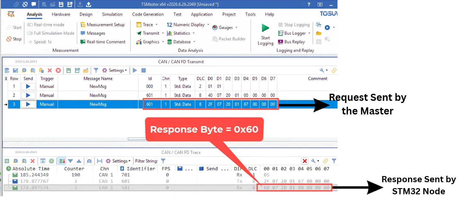
STM32 Node responds with command byte 0x60, confirming a successful write. Now to verify the data stored at 0x2007:01, we will perform a read operation again.
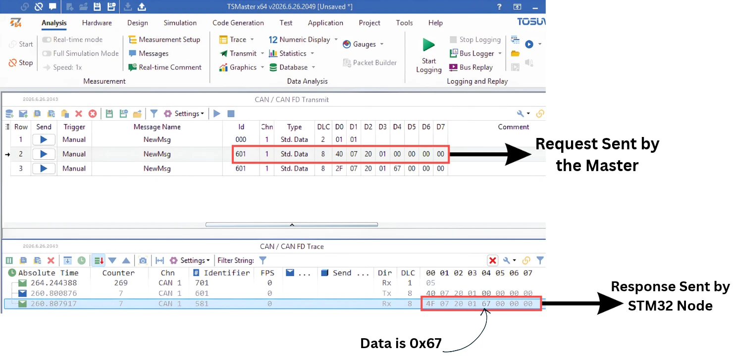
This confirms that the master is able to write and read data from our object. We successfully created a new object inside the object dictionary.
We’ll get into SDO commands and SDO communication in much more detail in an upcoming part of this series.
CANopen Object Dictionary – Frequently Asked Questions
Do I need a paid license to use CANopen Device Designer?
No. The evaluation version works fine for small projects, though it refuses to generate files once a project gets too complex, which is why we build new objects in a separate project and merge them in by hand.
Can I add more than one custom object at a time?
Yes, but each new object’s offset in od_assign depends on how many descriptors the previous objects used, so you need to calculate each offset carefully rather than copying it directly.
What happens if I read a subindex that was never defined?
The node responds with command byte 0x80, signaling a failed SDO request, and nothing gets logged on the serial console, since that address was never registered.
Why does adding one object require changes across three different files?
define.h tracks the overall counts, indices.h gives the object a readable name, and objdict.c stores its actual descriptors and data. Each file plays a different role, so all three need to stay in sync.
Can a record be mapped into a PDO the same way a variable can?
Yes, individual subindexes of an array or record can be PDO-mapped just like a variable. We’ll cover exactly how this works when we get to the PDO section later in this series.
Conclusion
We looked at how the object dictionary is divided into the communication, device, and application profiles, and what index and subindex actually mean. We also went through the different object types, variable, array, and record, and saw how each one is laid out differently. Using CANopen Device Designer, we added a new array object to our application profile, and made the matching changes across define.h, indices.h, and objdict.c. We then confirmed it worked over TSMaster, reading the entry count, writing a value, and reading it back correctly.
In the next parts of this series, we will connect this object dictionary to actual STM32 peripherals and sensors, so real data from our hardware can be read and transmitted over CANopen using SDOs and PDOs.
Download STM32 CANopen Object Dictionary Project Files
CubeMX project files and HAL source code with the custom object dictionary entry, tested on real hardware. Free to download — support the work if it helped you.
Browse More STM32 CANopen Tutorials

Subscribe
Login
0 Comments
Newest

