
Home ▸ Uncategorized ▸
Updated On: September 22, 2026
CANopen with STM32: CAN Configuration and Adding I-CUBE-CANOPEN
This is Part 2 of the CANopen with STM32 series. In Part 1, we covered what CANopen is, how it works as an application layer on top of CAN, and what kind of services it offers.
In this tutorial, we will configure the STM32 CAN peripheral, connect it to a master software running on a computer, and confirm that basic CAN communication is working. Once that is done, we will add the I-CUBE-CANOPEN library using STM32CubeMX and test the same setup again, this time using the CANopen protocol.
I have already covered STM32 CAN and FDCAN peripherals in separate tutorials. The I-CUBE-CANOPEN library by emotas supports both protocols, so depending on which one you want to use, you can configure that. I am going to use the CAN protocol with FDCAN peripheral, as it is the only one available in STM32H562.
This is the 2nd Part in the STM32 CANopen series. You can check the other tutorials below:
- PART 1: Understanding CANopen protocol
- Coming Soon…
CANopen with STM32 Part 2: CAN Configuration and Adding I-CUBE-CANOPEN — Video Tutorial
This video walks through configuring the FDCAN peripheral on STM32 for classical CAN, testing basic communication with TSMaster over a CANable adapter, and then adding the I-CUBE-CANOPEN library through STM32CubeMX.
Table Of Contents
- Hardware Connections for CANopen with STM32
- STM32CubeMX Configuration for CAN and FDCAN
- Writing the CAN Code in STM32CubeIDE
- Testing CAN Communication with TSMaster
- Implementing the I-CUBE-CANOPEN Library
- Testing CANopen Communication
- STM32 CANopen Overview – Frequently Asked Questions
- Download STM32 CANopen Part 2 Project Files
Hardware Connections for CANopen with STM32
The image below shows the hardware connection used in this project.
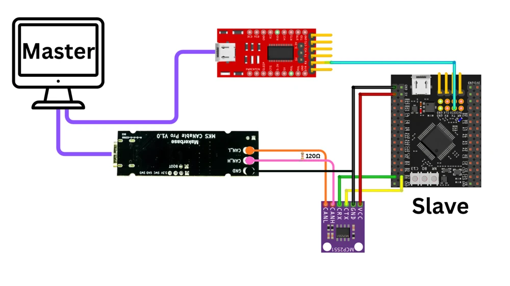
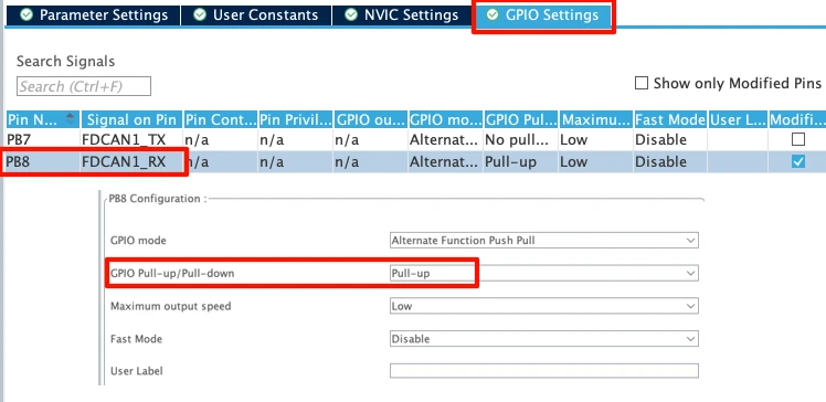
I am using an MCP2551 CAN transceiver connected to the STM32. The CAN TX pin goes to PB7, and the CAN RX pin goes to PB8. You can use any other transceiver as well.
The CANH and CANL pins from the MCP2551 connect to a CANable module, which works as a USB-to-CAN converter. We also need a 120 ohm resistor between CANH and CANL, since this acts as the terminating resistor for the bus.
For logging, I have a USB-to-TTL module connected to pin PA9, which is our UART TX pin.
I am using an STM32H562 board from WeAct Studio for this tutorial. I am also going to use the I-CUBE-CANOPEN library by emotas. This library is officially supported on the STM32G0, G4, H5, H7, L5, and U5 series only. For any other series, emotas offers a commercial package, and you would need to contact them directly for that.
STM32CubeMX Configuration for CAN and FDCAN
We need to test out CAN/FDCAN setup first. At this point I will not add the CANopen library. We will first configure the CAN/FDCAN peripheral, along with UART for serial logging. Once the CAN/FDCAN communication is working, we will again configure CubeMX to add the CANopen library also.
Clock Configuration
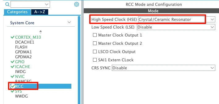
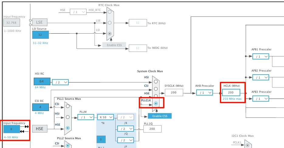
We will start with the clock configuration. I have enabled the external crystal as the clock source. This board has an 8 MHz crystal on it, and I am using the PLL to run the clock at 200 MHz.
CAN/FDCAN Peripheral Configuration
This STM32H562 does not have a classical CAN peripheral. Instead, it has an FDCAN peripheral. This is not a problem, since FDCAN is backward compatible with classical CAN, so we can still use the CAN protocol through it.
Here I am going to configure the FDCAN peripheral for classical CAN protocol. If you have CAN peripheral instead, you can go through my CAN Protocol tutorial to understand how to configure it. Similarly, if you want to use FDCAN protocol, you can go through the FDCAN tutorial to understand the configuration.
The image below shows the FDCAN configuration for the classical CAN protocol.
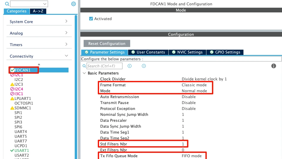
Since we want the FDCAN to behave as classical CAN, set the frame format to classic mode. Leave the remaining parameters at their defaults: mode set to normal, and auto retransmission, transmit pause, and protocol exception handling all disabled.
One setting we do need to change is the number of standard filters, since we will be using standard IDs. Set this to one or more, depending on how many IDs you plan to filter. When using in Mask Mode, 1 standard filter itself can filter 2048 possible IDs (0x000–0x7FF).
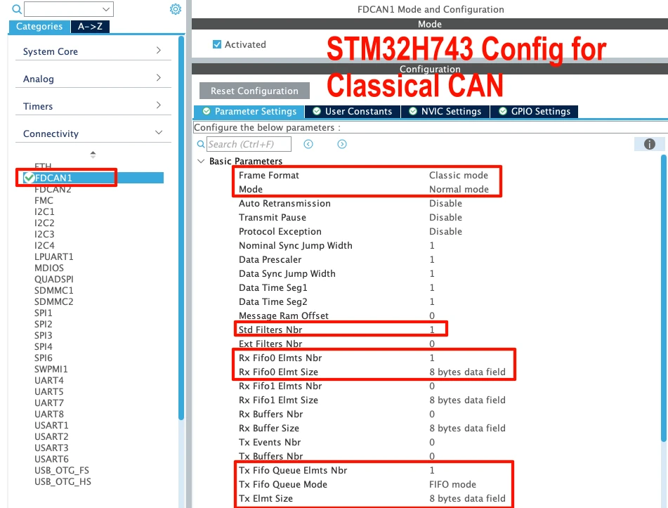
If your FDCAN peripheral has RX FIFO 0 and TX FIFO queue element settings, set the element number to 1 for each. Set the element size to 8 bytes for classical CAN. Below is the image showing such configuration for the STM32H743.
CAN Bit Timing for 500 kbps
We need to first provide a decent clock to the FDCAN peripheral. The image below shows the FDCAN clock configuration.
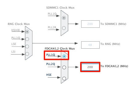
I am using PLL1Q clock source to provide 200 MHz clock to the FDCAN.
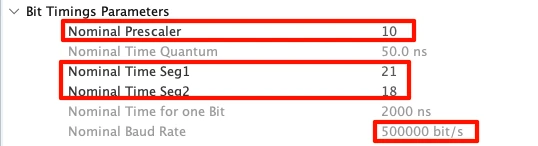
Now we need to adjust the prescaler and the nominal time segment values until the baud rate reads 500 kbps. Keep the time segment values in a reasonable range, roughly between 10 and 20.
NVIC and GPIO Settings
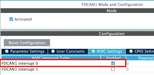
Go to the NVIC settings and enable the FDCAN interrupt 0. This is used later to receive CAN messages in FIFO 0.
Then go to the GPIO settings and make sure the pull-up is enabled for the RX pin.
UART Configuration for Logging
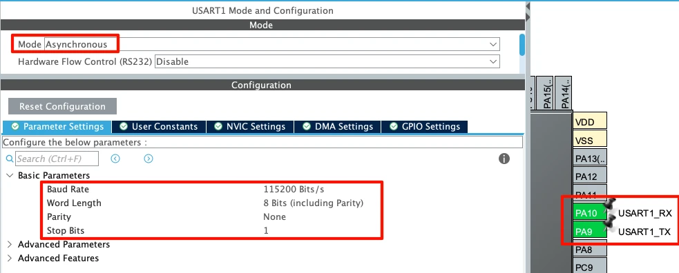
We also need UART for serial logging. I am using UART1, with pins PA9 and PA10. Leave the remaining parameters at their defaults: 115200 baud, 8 data bits, no parity, and 1 stop bit.
Writing the CAN Code in STM32CubeIDE
Scroll down in main.c and you will find the CAN initialization function, generated according to our CubeMX configuration.
Configuring the Filter
After initializing the peripheral, we need to configure the filters, so we can control which IDs our device accepts messages from. I have covered filter configuration in detail in CAN tutorial, so check those if you want a deeper explanation.
  /* USER CODE BEGIN FDCAN1_Init 2 */

  FDCAN_FilterTypeDef sFilterConfig;

  sFilterConfig.IdType = FDCAN_STANDARD_ID;
  sFilterConfig.FilterIndex = 0;
  sFilterConfig.FilterType = FDCAN_FILTER_MASK;
  sFilterConfig.FilterConfig = FDCAN_FILTER_TO_RXFIFO0;
  sFilterConfig.FilterID1 = 0x123;
  sFilterConfig.FilterID2 = 0x7FF;
  if (HAL_FDCAN_ConfigFilter(&hfdcan1, &sFilterConfig) != HAL_OK)
  {
    /* Filter configuration Error */
    Error_Handler();
  }

  HAL_FDCAN_ConfigGlobalFilter(&hfdcan1, FDCAN_REJECT, FDCAN_REJECT, FDCAN_REJECT_REMOTE, FDCAN_REJECT_REMOTE);

/* USER CODE END FDCAN1_Init 2 */For our filter, the ID type is standard ID, and the filter index is 0. We use the mask filter type, with filtered data sent to RxFifo0. Filter ID 1 is set to 0x123, which is the ID we want to receive data from. Filter ID 2 is the mask, and since we only want messages from this exact ID, it is set to 0x7FF. This way, every bit of the incoming ID is compared, and only an exact match is passed to RxFifo0.
We also need a global filter configuration, which rejects all messages except the one we specifically configured. The function HAL_FDCAN_ConfigGlobalFilter is set to reject all non-matching standard and extended CAN frames, as well as remote frames.
Redirecting printf to UART
Define a custom _write function so our print statements are logged through UART.
int _write(int fd, unsigned char *buf, int len) {
  if (fd == 1 || fd == 2) {
    HAL_UART_Transmit(&huart1, buf, len, 999);
  }
  return len;
}I am using UART1 here, since that is what we configured in CubeMX.
Transmitting and Receiving CAN Messages
To send data, we need to define a TX header along with the data we want to transmit, and then call HAL_FDCAN_AddMessageToTxFifoQ to send it over the CAN bus.
Inside main, after all the peripherals are initialized, we start the FDCAN peripheral, activate the receive notification, and set up the TX header along with the data:
HAL_FDCAN_ActivateNotification(&hfdcan1, FDCAN_IT_RX_FIFO0_NEW_MESSAGE, 0);

HAL_FDCAN_Start(&hfdcan1);

FDCAN_TxHeaderTypeDef TxHeader;
uint8_t TxData[8] = {
    0x11, 0x22, 0x33, 0x44,
    0x55, 0x66, 0x77, 0x88
};

TxHeader.Identifier = 0x321;
TxHeader.IdType = FDCAN_STANDARD_ID;
TxHeader.TxFrameType = FDCAN_DATA_FRAME;
TxHeader.DataLength = FDCAN_DLC_BYTES_8;
TxHeader.ErrorStateIndicator = FDCAN_ESI_ACTIVE;
TxHeader.BitRateSwitch = FDCAN_BRS_OFF;
TxHeader.FDFormat = FDCAN_CLASSIC_CAN;
TxHeader.TxEventFifoControl = FDCAN_NO_TX_EVENTS;
TxHeader.MessageMarker = 0;Here, the device ID is set to 0x321, which is the ID of our STM32. We are using a standard ID, transmitting a data frame, and the DLC is set to 8 bytes, since we are sending 8 bytes of data. The frame format is set to classical CAN, since that is what we are testing at this stage.
With the TX header configured, we transmit this message inside the infinite loop, once every second:
while (1)
{
  if (HAL_FDCAN_AddMessageToTxFifoQ(&hfdcan1, &TxHeader, TxData) != HAL_OK)
  {
    Error_Handler();
  }
  HAL_Delay(1000);
}This is the message that will be transmitted from the STM32 over the CAN bus, and it is what we will see arriving in the trace window on our master software shortly.
In order to receive data, we call HAL_FDCAN_ActivateNotification (already shown above). This sets up a notification so that whenever a message is pending in RxFifo0, an interrupt is triggered and HAL_FDCAN_RxFifo0Callback is called. This is where we process the received data:
void HAL_FDCAN_RxFifo0Callback(FDCAN_HandleTypeDef *hfdcan, uint32_t RxFifo0ITs)
{
  if ((RxFifo0ITs & FDCAN_IT_RX_FIFO0_NEW_MESSAGE) != 0)
  {
    FDCAN_RxHeaderTypeDef RxHeader;
    uint8_t RxData[8];

    HAL_FDCAN_GetRxMessage(hfdcan, FDCAN_RX_FIFO0, &RxHeader, RxData);

    printf("Received from ID: 0x%03lX, Data: ", RxHeader.Identifier);

    for (int i = 0; i < 8; i++)
    {
      printf("%02X ", RxData[i]);
    }

    printf("\r\n");
  }
}Here, we first call HAL_FDCAN_GetRxMessage to retrieve the RX header and RX data from the received message. Then we print the ID of the transmitter along with the data it has sent.
Testing CAN Communication with TSMaster
Now we will configure our master software. I am using TSMaster for this purpose as it supports the CANable module.
Setting Up TSMaster
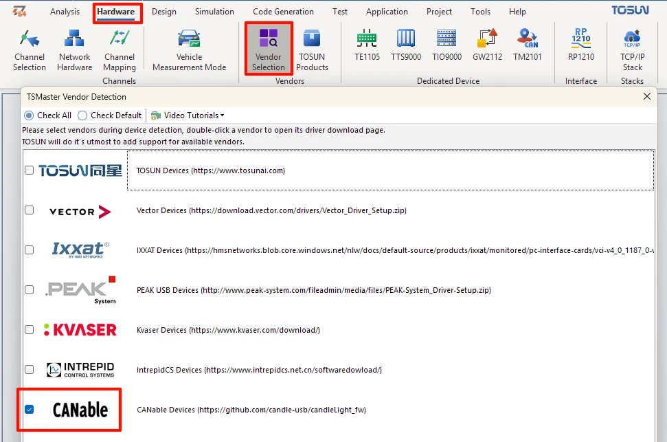
Go to Hardware -> Vendor Selection, and make sure the CANable vendor is checked, since that is the adapter we are using.
If you are running this inside a VM, make sure the USB device is passed through to Windows, or the software will not detect it.
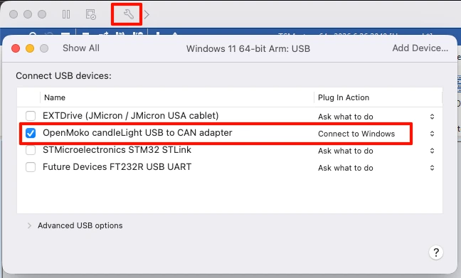
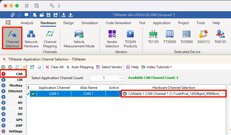
Then go to Channel Selection, and select the CANable device under CAN Setting.
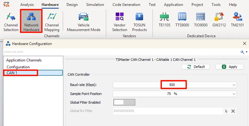
Go to Network Hardware Properties, select CAN1, and set the baud rate to 500 kbps, matching what we configured on the STM32.
From the Analysis tab, add a Transmit window and a Trace window.
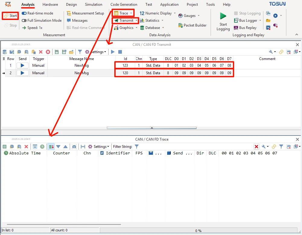
In the Transmit window, add a message with ID 0x123, DLC 8, and data bytes 1 through 8, since this is the ID our filter is configured to accept. Add one more message from a different ID, just to check whether our device correctly ignores it.
Verifying the Communication
Flash the project and open a serial logger connected to the USB-to-TTL port at 115200 baud.
Click Start on TSMaster. You should see the blue LED on the CANable module light up, and the trace window should show messages coming in from ID 0x321 every second, matching what we set up in the STM32 code.
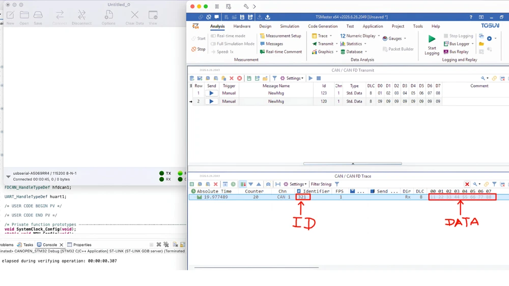
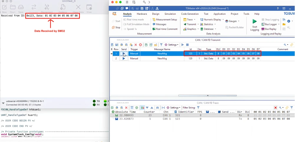
Transmit a message from TSMaster on ID 0x123, and it should appear on the serial console with the correct ID. This confirms communication is working in both directions.
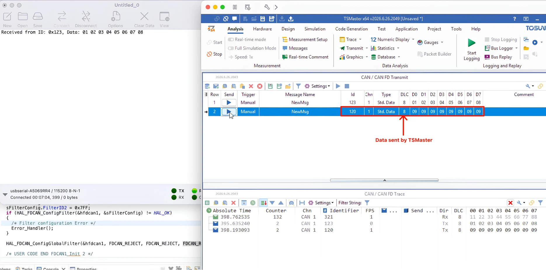
Now, when I send a message from a different ID, the STM32 rejects it. This is according to our filter configuration.
Implementing the I-CUBE-CANOPEN Library
Adding the Library
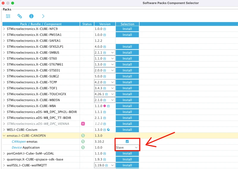
Now we will add the CANopen protocol on top of this CAN communication. Go back to STM32CubeMX, and under Software Packs, select Select Components, and browse down to I-CUBE-CANOPEN.
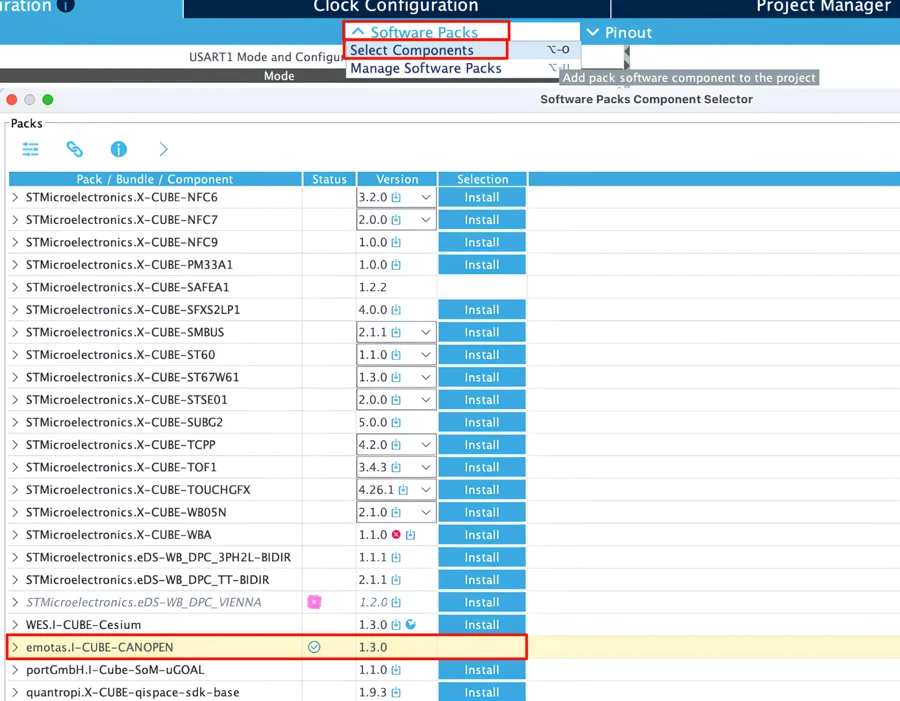
If you have not installed it yet, you will see an Install option here to install it.
Once installed, expand this section, check CANopen emotas, and select slave mode under Device Application.
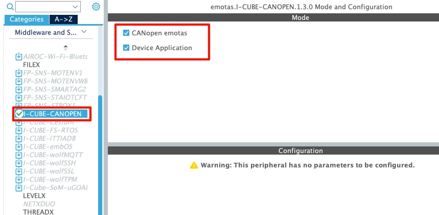
Then go to the Middleware Configuration tab, and under I-CUBE-CANOPEN, check both options provided. There is no configuration available here, so simply generate the project again.
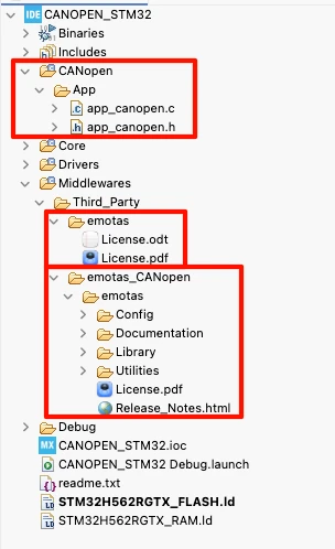
Once the project is generated, you should see the CANopen folders added in our previously created project.
Inside main.c, MX_CANopen_Init is called during initialization, and MX_CANopen_Process is called inside the infinite loop.
  /* Initialize all configured peripherals */
  MX_GPIO_Init();
  MX_FDCAN1_Init();
  MX_ICACHE_Init();
  MX_USART1_UART_Init();
  MX_CANopen_Init();

    while (1)
  {
    /* USER CODE END WHILE */

    MX_CANopen_Process();
    /* USER CODE BEGIN 3 */
}Modifying the library
Open app_canopen.c. Inside the function MX_CANopen_Init, the bit rate here is set to 250 kbps by default, so change it to 500, matching our master software.
void MX_CANopen_Init(void)
{
UNSIGNED16 bitRate = 500u;

	/* hardware initialization */
	/* this is function is empty
	 * since STM32CubeMX generated CPU clock and GPIO initialization code */
	codrvHardwareInit();

	/* USER CODE BEGIN INIT BITRATE */
	bitRate = 500u;
/* USER CODE END INIT BITRATE */Next, go to Middlewares -> Third_Party -> emotas_CANopen -> emotas -> config folder and open gen_define.h. Here, the CAN clock is set to 40 MHz, which is incorrect, since we are not using a 40 MHz clock. These clock values are defined inside the codrv_canbittiming.c file, which lists configurations ranging from 4 MHz up to 200 MHz. Since we configured the CAN clock at 200 MHz earlier, copy the correct definition from that file and paste it into gen_define.h.
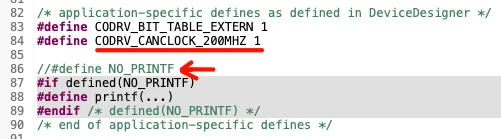
Also comment out the NO_PRINTF section, since we do want to print logs to the console.
Modifying the code
We configured the STM32 to accept messages only from 0x123, but CANopen communicates using several different IDs. The NMT command uses ID 0x000, and the heartbeat uses IDs in the 0x700–0x77F range. A single narrow filter like ours blocks all of this. So instead of filtering for one specific ID, open the filter to accept all incoming CAN IDs. This way, the CANopen library can receive every message it needs and decide internally what to process.
Set both the filter ID and mask to 0, and comment out the global filter configuration, since we no longer want to reject anything.
  /* USER CODE BEGIN FDCAN1_Init 2 */

  FDCAN_FilterTypeDef sFilterConfig;

  sFilterConfig.IdType = FDCAN_STANDARD_ID;
  sFilterConfig.FilterIndex = 0;
  sFilterConfig.FilterType = FDCAN_FILTER_MASK;
  sFilterConfig.FilterConfig = FDCAN_FILTER_TO_RXFIFO0;
  sFilterConfig.FilterID1 = 0;
  sFilterConfig.FilterID2 = 0;
  if (HAL_FDCAN_ConfigFilter(&hfdcan1, &sFilterConfig) != HAL_OK)
  {
    /* Filter configuration Error */
    Error_Handler();
  }

/* USER CODE END FDCAN1_Init 2 */To test CANopen, comment out all the code we wrote earlier for plain CAN testing inside main.c. Also comment out the FDCAN interrupt handler generated by CubeMX, since the CANopen library implements its own interrupt handler.
//void FDCAN1_IT0_IRQHandler(void)
//{
//  /* USER CODE BEGIN FDCAN1_IT0_IRQn 0 */
//
//  /* USER CODE END FDCAN1_IT0_IRQn 0 */
//  HAL_FDCAN_IRQHandler(&hfdcan1);
//  /* USER CODE BEGIN FDCAN1_IT0_IRQn 1 */
//
//  /* USER CODE END FDCAN1_IT0_IRQn 1 */
//}Testing CANopen Communication
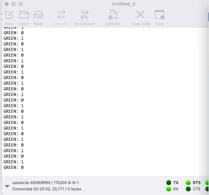
After flashing the project, you should see logs printed continuously, showing that the device is running correctly.
The trace window on the TSMaster shows a heartbeat message every second, with the ID 0x77F.
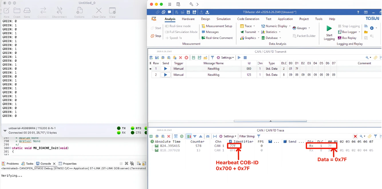
Here, 0x700 is the heartbeat COB-ID, and 0x7F is the node ID of our STM32. The data sent, 0x7F, indicates the node is in pre-operational mode.
Now let’s check whether the STM32 can receive data, by sending a command to switch this node to operational mode. Use ID 0x000, with a DLC of 2, and data bytes 0x01 followed by 0x7F, where 0x01 sets the node to operational mode and 0x7F is the node ID.
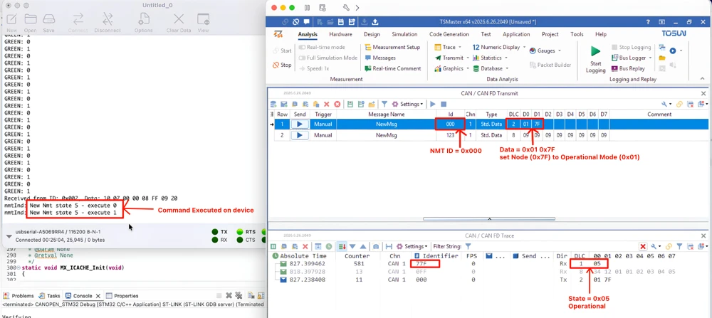
The state 5 is applied on the STM32 node, indicating operational mode. The heartbeat also now shows the data value 5, confirming the node is operational.
So our STM32 is now communicating with TSMaster using the CANopen protocol. This sets up the foundation for everything we will build on in the rest of this series, since every future tutorial will rely on this same working CAN and CANopen.
STM32 CANopen Overview – Frequently Asked Questions
Why does the STM32H562 use FDCAN instead of a classical CAN peripheral?
Newer STM32 series, including H5, moved to the FDCAN peripheral across the board. Setting the frame format to classical mode makes it behave exactly like a regular CAN controller.
Why did the STM32 still receive messages from an ID that was not in the filter?
A mask filter only defines which messages get accepted into a FIFO. Without a global filter set to reject unmatched IDs, everything else still passes through by default.
Why does CANopen need the filter opened up completely?
CANopen uses several different IDs for its own services, such as NMT and heartbeat. A narrow filter built for one custom ID blocks most of this traffic, so the filter needs to be opened so the library can handle the filtering internally.
What does the heartbeat data value indicate?
The single data byte in a heartbeat message reflects the node’s current NMT state. In this tutorial, 0x7F meant pre-operational, 5 meant operational, and 4 meant stopped.
Is the I-CUBE-CANOPEN library free to use on any STM32?
It is officially supported at no extra cost only on the G0, G4, H5, H7, L5, and U5 series. For other STM32 families, emotas offers it only as a commercial package.
Conclusion
We saw how to configure the CAN or FDCAN peripheral, verify communication with a master software, and then add the CANopen library on top of it to get the same communication running through CANopen. The earlier code used for testing plain CAN communication is still there in the project, just commented out. Starting from the next tutorial, I will remove it completely, since we will not need it going forward.
Our STM32 node is now completely ready for the CANopen protocol. It transmits heartbeat messages and correctly responds to NMT commands, switching between pre-operational, operational, and stopped states, all confirmed over TSMaster.
In the next part, we will look into the object dictionary, the kind of elements stored inside it, and how to add our own custom data to it.
Download STM32 CANopen Part 2 Project Files
CubeMX project files and HAL source code with I-CUBE-CANOPEN, tested on real hardware. Free to download — support the work if it helped you.
Browse More STM32 CANopen Tutorials
ESP32 UART LED Control via UART2 — ESP-IDF Tutorial
How to Interface LCD1602 via I2C on ESP32 with ESP‑IDE
How to Read & Write MPU6050 with ESP‑IDE | I2C PART 2
ESP32 SPI Tutorial Part 1: Configure & Transmit
ESP32 SPI Tutorial Part 2: Read Data from Slave

Subscribe
Login
0 Comments
Newest

